
Contents
- 1. Introduction
- 2. Main Functions
- 3. Hardware Requirements
- 4. Software Environment
- 5. File Structure
- 6. Document Description
- 7. Core Ideas of Software Design
- 8. Instructions for Use
- 9. Sample Program
- 10. Notes
- 11. Version Record
- 12. Contact the Developer
- 13. Licensing Agreement
- Appendix 1: Project Source Code Download
- Appendix II: Reference Materials for hardware Modules
- Version Record
1. Introduction
1.1 Project Background
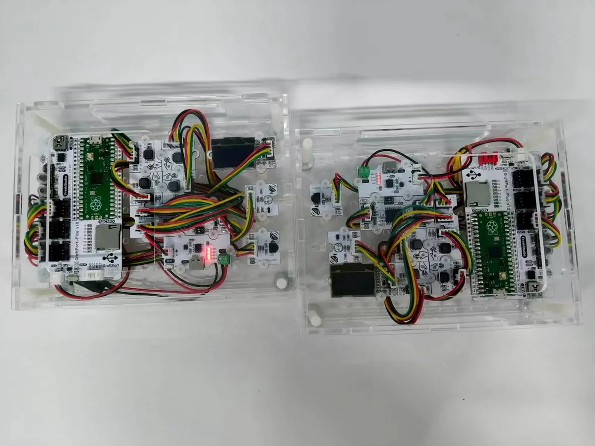
Traditional infrared communication systems mostly adopt unidirectional transmission or have a single function, lacking intuitive data display and interactive feedback capabilities.This project is based on the GraftPort-RP2040 development board, and integrates an 8-bit IO port expansion module based on PCF8574 to connect 4 mechanical key modules, an infrared transmitting module based on IR333C, an infrared receiving module based on TSOP34138 and a 0.96-inch SSD1306-OLED module to realize an integrated system of "infrared data transmission - display - interactive feedback", which solves the problem of poor interactivity of traditional infrared communication systems. Meanwhile, it incorporates MicroPython 's efficient task scheduling and state management mechanism to ensure the stable operation of the system.
1.2 Overview of the Main Functions of the Project
This project is developed based on MicroPython PCF8574 IO expansion module, send corresponding letter data through the infrared transmitting module based on IR333C, receive data via the infrared receiving module based on TSOP34138, and display the real-time transceiving status on the OLED display screen. It supports automatic transmission interval control, has a built-in automatic display status clearing mechanism, and is equipped with exception capture and debug information output functions to facilitate problem locating.
1.3 Applicable Scenarios or Application Area
- Educational experiment: for teaching demonstration of infrared communication principles, showcasing the processes of data encoding, transmission and decoding;
- Remote Control System: As a prototype system of a simple infrared remote controller, it can be used for equipment control and signal forwarding.
- IoT nodes: In scenarios where radio waves cannot be utilized, short-range data communication is implemented via infrared technology;
- Interactive Device: Applicable to scenarios requiring contactless communication, such as interactive art installations and smart home control systems.
2. Main Functions
- Infrared Data Transceiver: Supports
NECprotocol-based infrared data transmission and reception, with automatic duplicate code processing; - Key Status Detection: Pass 8-bit I/O port expansion module based on PCF8574 detects the status of 4 independent keys;
- OLED real-time display: via 0.96-inch SSD1306-OLED module to display the status of transmitted and received data in real time;
- Automatic transmission control: Automatically send the letter data corresponding to the current key every 3 seconds;
- Display Status Management: The transmitted and received data will be automatically cleared after being displayed for 5 seconds to avoid information accumulation on the screen;
- Exception fault tolerance mechanism:
I2Cautomatically retries when device initialization fails, and triggersLEDflashing alarm in case of severe errors; - Flexible board-level adaptation: based on
board.py, it decouples pin mapping and supports subsequent expansion to otherRP2040development boards.
3. Hardware Requirements
3.1 Hardware Required
The project is based on the GraftPort-RP2040 development board as the main controller:
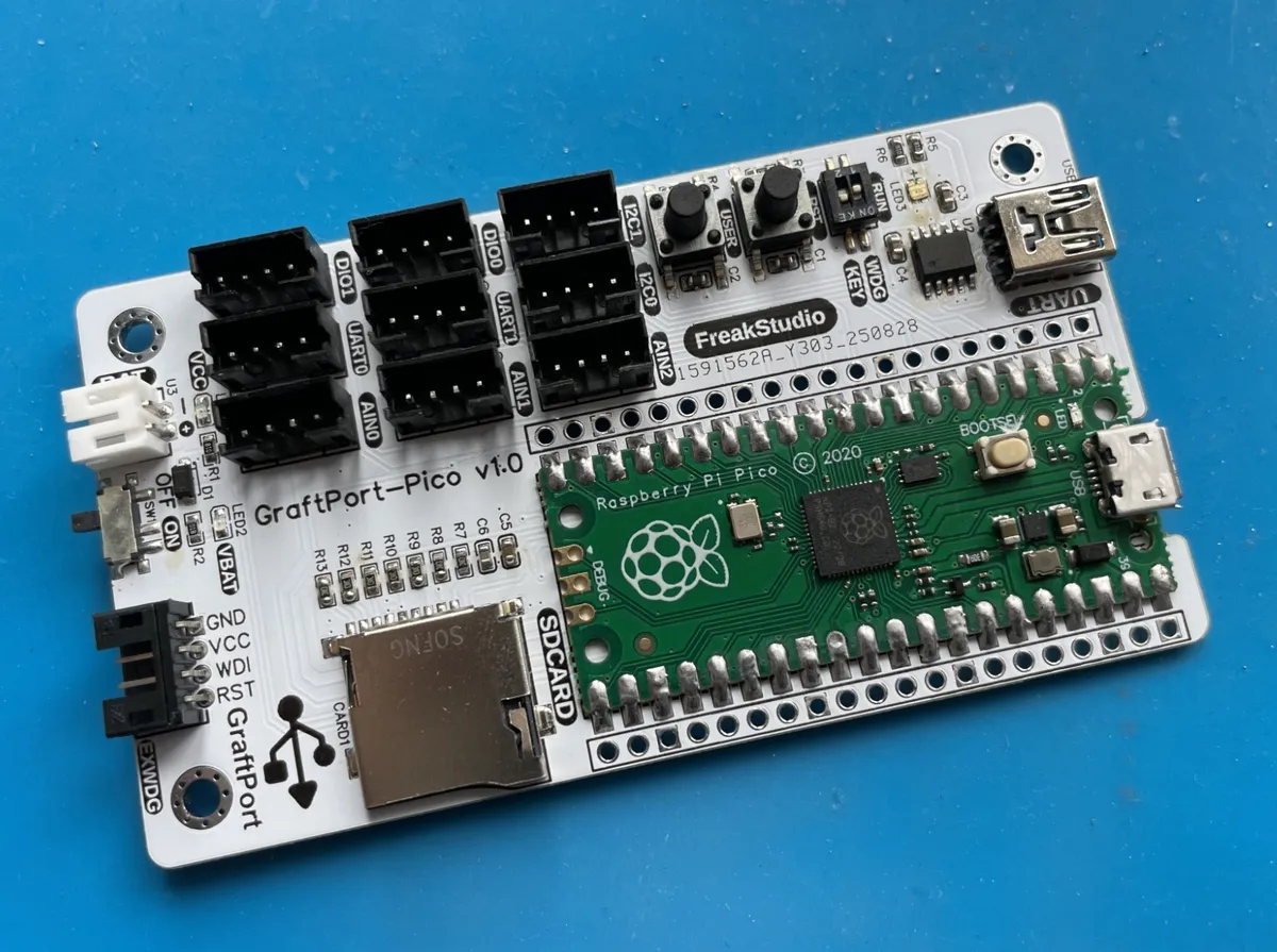
The other required modules include:
#Figure (Photos of the modules used)
- GraftSense: 8-bit IO Port Expansion Module Based on PCF8574:(
I2CCommunication, for Key Status Detection); - GraftSense - An Infrared Transmitter Module Based on IR333C:(connect to the
DIOinterface, supporting 38kHz carrier); - GraftSense - An Infrared Receiving Module Based on TSOP34138:(connect to the
DIOinterface, supports C protocol decoding); - GraftSense 0.96-inch SSD1306 OLED module:(
I2Ccommunication, address0x3Cor0x3D); - GraftSense-SY7656 Lithium Battery Charge-Discharge Module:(connects to polymer lithium battery, outputs 5V voltage, equipped with
Type-Ccharging port); - Onboard LED: By default, it uses the fixed pins of the development board, so no additional wiring is required.
3.2 Hardware Connection
8-bit I/O Port Expansion Module Based on PCF8574: Connected via PH2.0 connecting cable to the I2C0 interface;
Mechanical Key Module: connect to the 8-bit I/O port expansion module based on PCF8574 for key expansion (all four mechanical keys need to be connected to the 8-bit I/O port expansion module)
Infrared transmitting module based on IR333C: connected via PH2.0 connecting cable to DIO0 interface;
Infrared receiving module based on TSOP34138: connected to PH2.0 cable to access DIO1 interface;
0.96-inch SSD1306-OLED module: connected via PH2.0 connector cable to I2C1 interface.
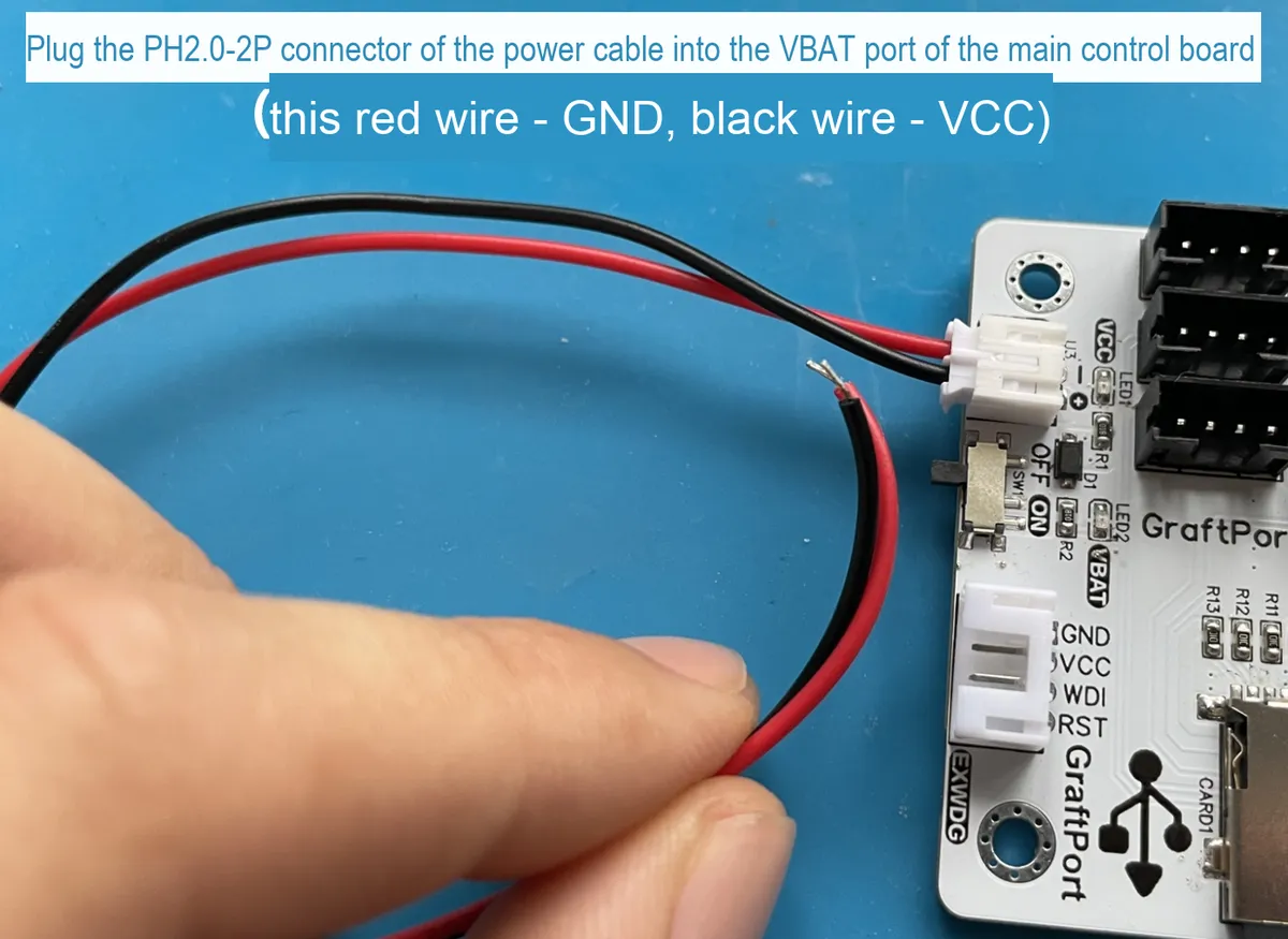
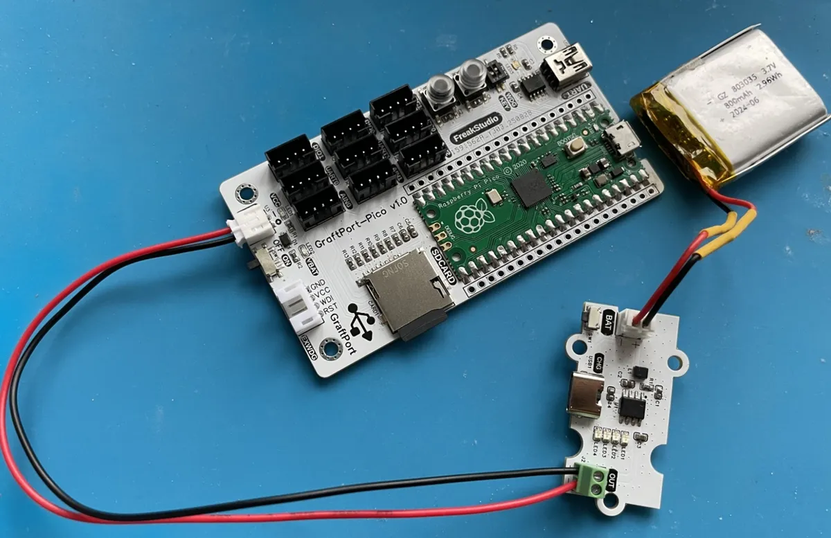
Lithium Battery Charge and Discharge Module: BAT interface connects to the lithium battery, and the OUT interface supplies power to the main control board via a PH2.0-2P connection cable.
3.3 Structural Assembly
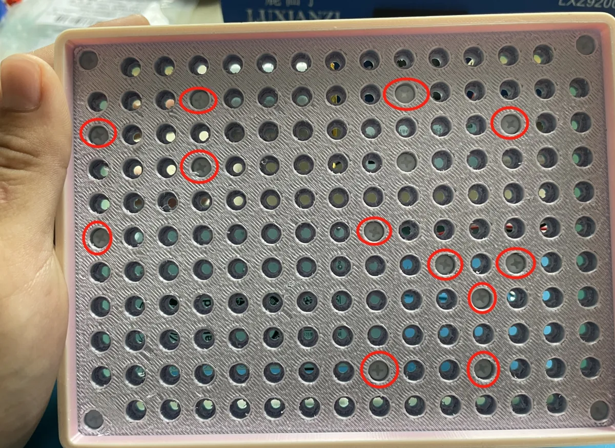
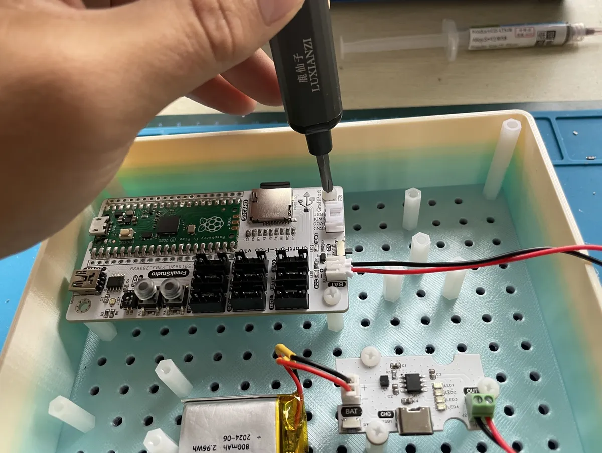
First, use M3 plastic pillars to fix each module and the main control board to the bottom plate of the housing (M3 screw holes are pre-drilled on both the main control board and the housing):
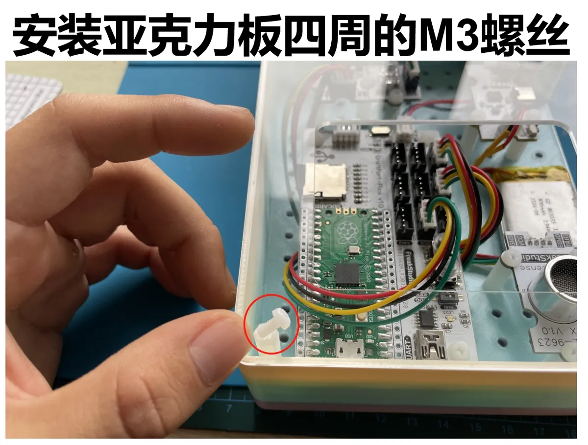
Next, secure the periphery of the housing with M3 plastic pillars, then screw in M3 screws at the corresponding positions to complete the assembly:
3.4 Notes
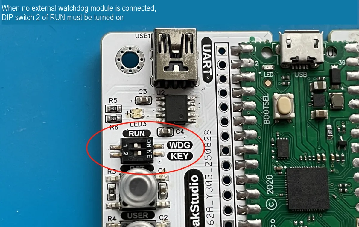
When the main control board is not connected to an external watchdog module, the RUN DIP switch 2 must be turned on:
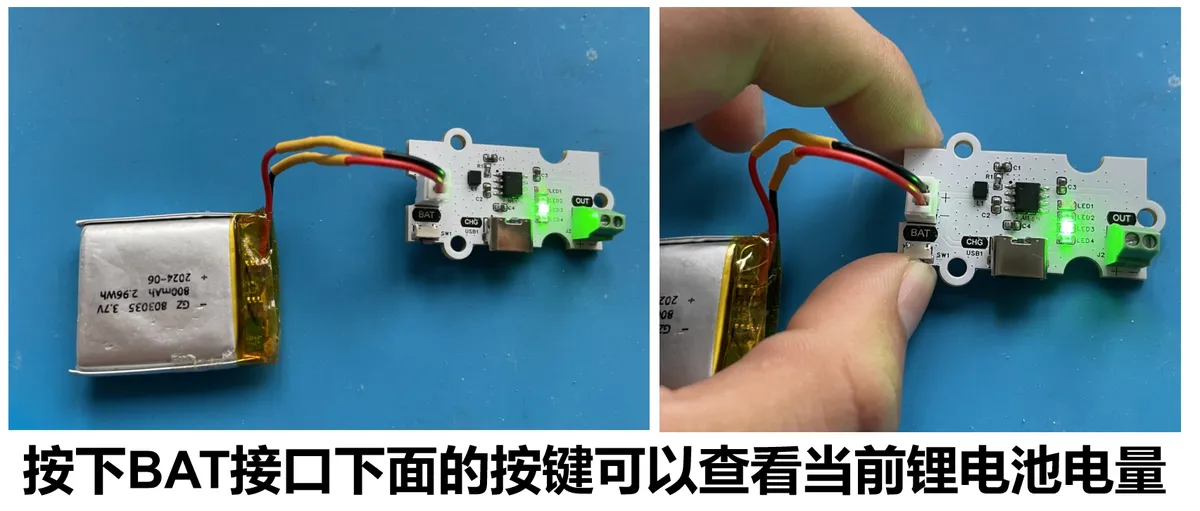
The lithium battery charge-discharge module supports power level display, and can be charged via the Type-C interface below:
4. Software Environment
- Core firmware:
MicroPython v1.23.0(need to adapt toGraftPort-RP2040, supportmachine.Pin/I2C/Timermodule, soft timer scheduling); - Development IDE:
PyCharm(for code writing, uploading and debugging, supportsMicroPython REPLinteraction, and requires the installation of theMicroPythonplugin); - Accessory Tools:
Python 3.12+(optional, for running local helper scripts such as firmware flashing scripts);mpy-cross v1.23.0(used to compile.pyfiles into. mpyto reduce the memory usage of the development board, optional);mpremote v0.11.0+(replacesThonnyfor file upload, supports command-line operations, optional);
- Dependency Modules: No additional third-party libraries are required, and all drivers (including
passive_buzzer_driver.pyand others) are custom-implemented and provided along with the project files.
5. File Structure
infrared_transceiver
├─ LICENSE
├─ tools
│  ├─ dependency_analyzer.py
│  ├─ mpy_compiler.py
│  ├─ mpy_uploader.py
│  └─ README.md
├─ firmware
│  ├─ board.py
│  ├─ boot.py
│  ├─ conf.py
│  ├─ main.py
│  ├─ tasks
│  │  └─ tasks_here
│  ├─ libs
│  │  └─ libs_here
│  └─ drivers
│     ├─ __init__.py
│     ├─ ssd1306_driver
│     └─ irtranslation_driver
├─ examples
│  └─ README.md
├─ docs
└─ build
6. Document Description
main.py: Project entry point, with core logic including:- Definition of global state variables (transmit-receive status, display control flags, etc.);
- Hardware initialization: onboard
LED, infrared transceiver module,I2Cperipherals,PCF8574andSSD1306; I2CDevice Verification Mechanism: automatically scans and verifies device addresses, and retries upon failure;- Main loop control: key status detection, automatic transmission control, display status update and clearing;
- Callback function: including infrared reception callback and transmission completion processing.
drivers/pcf8574_driver.py:PCF8574IOexpansion driver, key functions:- Port read and write operations, supporting 8-bit
IOexpansion; - Key press state detection and debounce processing.
- Port read and write operations, supporting 8-bit
drivers/irtranslation_driver.py: Infrared transceiver driver, key functions:NECprotocol encoding and decoding;- 38kHz carrier generation;
- Callback for infrared data transmission and reception.
drivers/ssd1306_driver. py: SSD1306 OLED display driver, key functions:I2Ccommunication initialization;- Screen control (screen clearing, display, text output);
- Area update and clearing.
board.py: A board-level pin mapping module that defines theBOARDSdictionary (including the fixed pins ofGraftPort-RP2040and the mapping ofI2C/DIOinterfaces), provides interfaces such asget_fixed_pinandget_i2c_pins, and realizes the decoupling of board-level configuration from business logic.conf.py: a user configuration file. The parameters that require manual definition by the user include:I2C_INIT_MAX_ATTEMPTS(number of device initialization retries),I2C_INIT_RETRY_DELAY_S(retry interval in seconds), andENABLE_DEBUG(debug print switch); the system will use default values if these parameters are not defined.
7. Core Ideas of Software Design
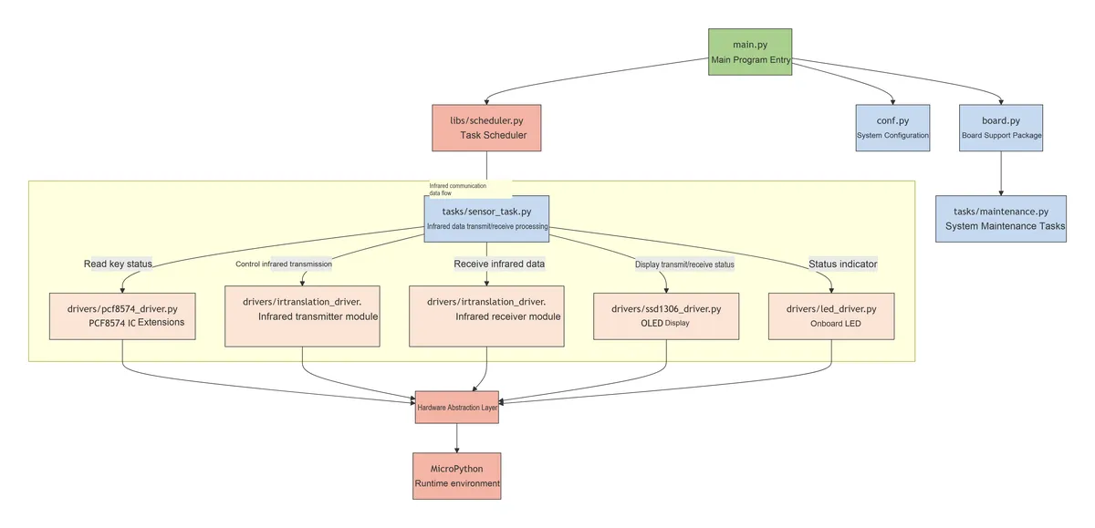
- finite-state machine Design pattern: adopt a management mechanism based on state flags
- Transmit-Receive State Separation:
the tx_pendingandrx_pendingflags manage the transmit and receive states respectively to avoid race conditions; - Display update asynchronization: The callback function only sets the status flag, and the main loop uniformly handles display updates to ensure the thread safety of display operations;
- Automatic Clearance Mechanism: Automatic clearing of the display area based on timestamps to keep the interface tidy.
- Transmit-Receive State Separation:
- Event-Driven Architecture: Blend Mode combining interrupts and polling
- Infrared reception interrupt: Responds to infrared data reception in real time to ensure no data frames are lost;
- Main loop polling: periodically detect the key status, process display updates, and manage automatic transmission;
- Time-triggered Task: Executes periodic tasks regularly based on system ticks.
- Resource Management Optimization: Efficient Utilization of System Resources
- I2C Bus Multiplexing: Multiple
I2Cdevices share the bus and are distinguished by different addresses; - Display partial updates: Only update the changed display area to reduce the frequency of full-screen refresh;
- Memory-friendly design: Avoid executing complex operations in interrupts to prevent memory fragmentation.
- I2C Bus Multiplexing: Multiple
- Error Handling Mechanism: Multi-layered Protection Ensures System Stability
- Device initialization retry:
I2Cautomatically retry multiple times when device initialization fails; - Communication timeout handling: A reasonable timeout mechanism shall be set for infrared communication;
- Status Consistency Check: Conduct status verification before and after critical operations.
- Device initialization retry:
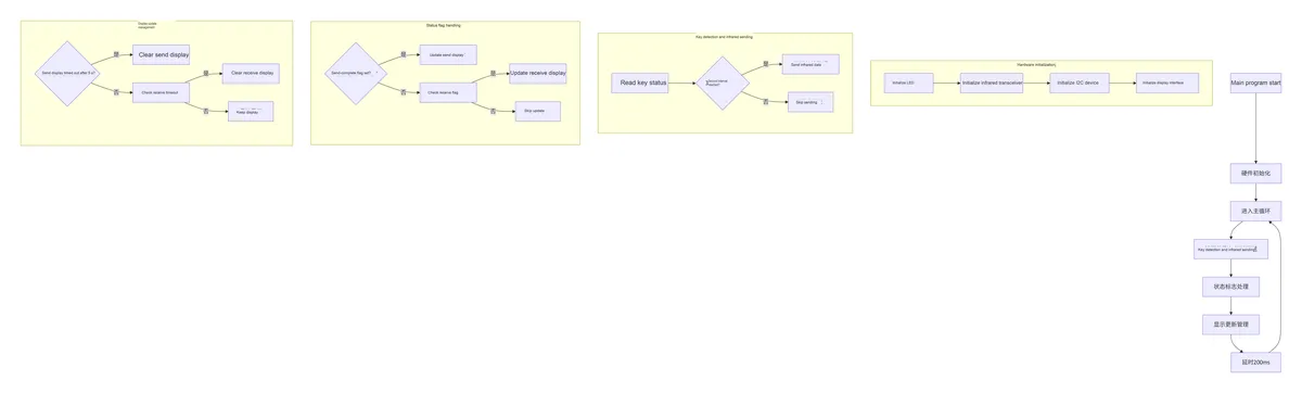
- Data Flow Control Process: The data flow control process is as follows
8. Instructions for Use
8.1 Hardware Connection
Connect the main control board, each sensor module and the battery according to the connection method specified in the "hardware requirements";
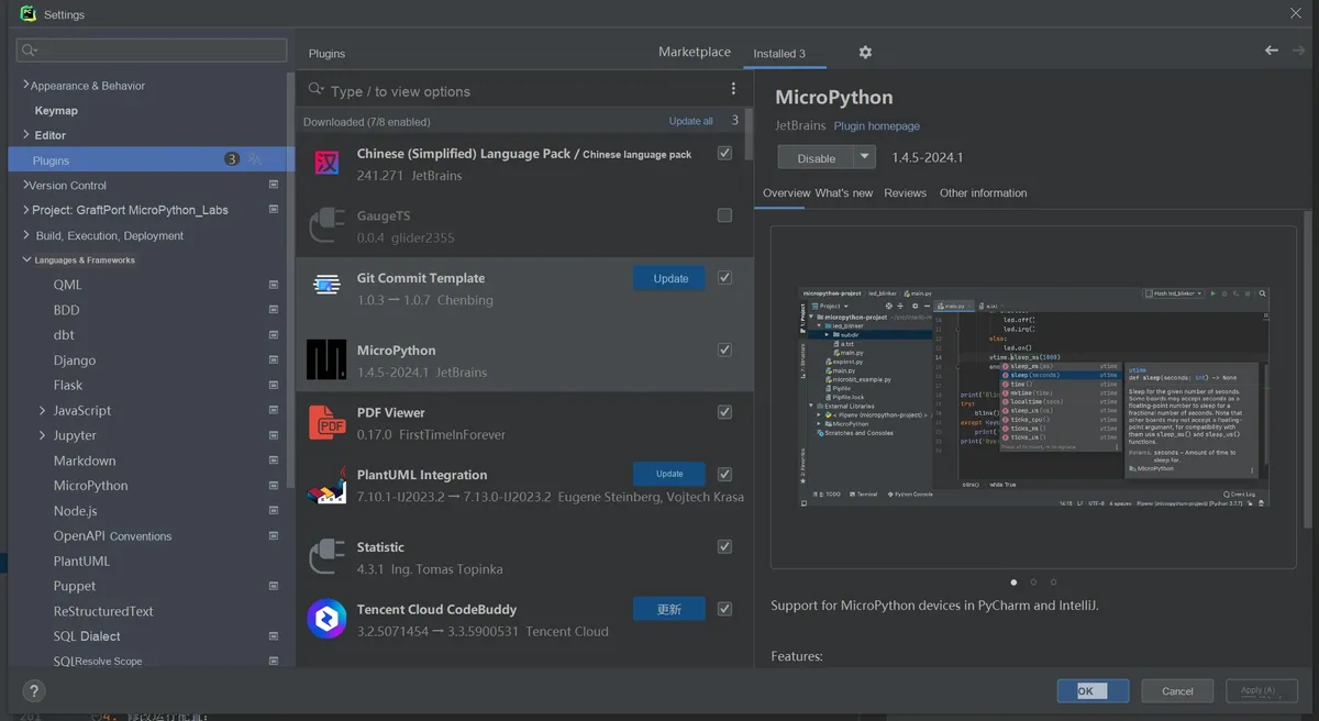
8.2 Run the Project (Using PyCharm + MicroPython Plugin)
Open PyCharm and install the corresponding MicroPython plugin.
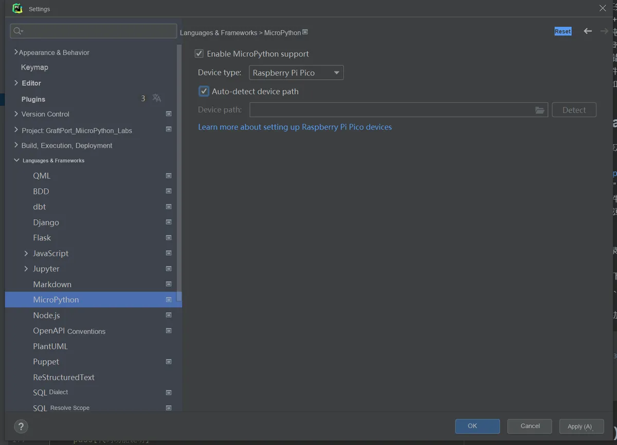
In the plugin, select Target Device as RP2040, and enable Auto-detect device path.
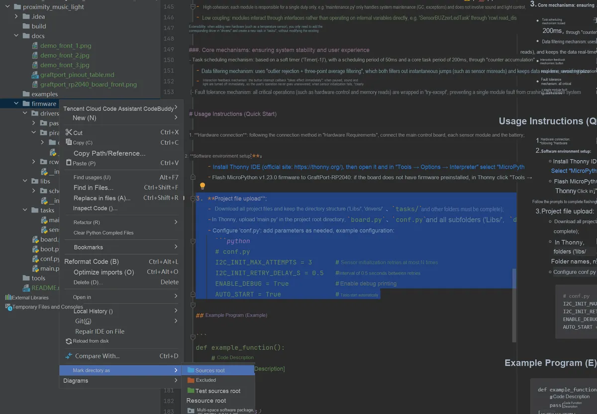
Set Project/firmware as the project root directory.
Modify runtime configuration:
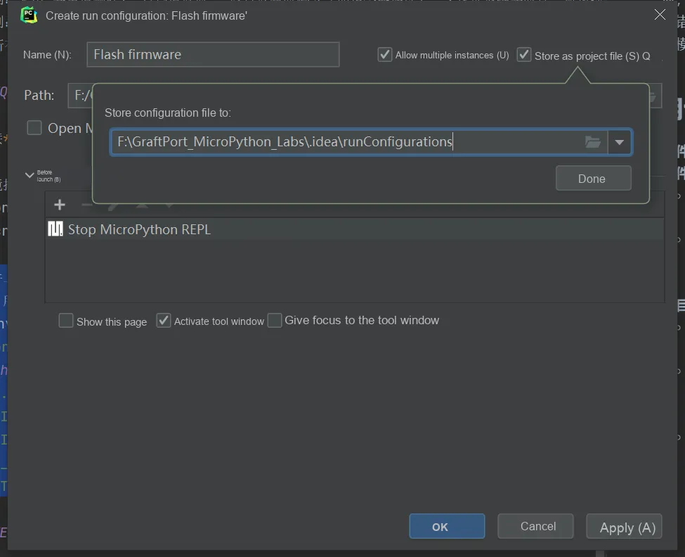
- Check
Allow multiple instances - Select
Store as project file - Click
OKto save the configuration.
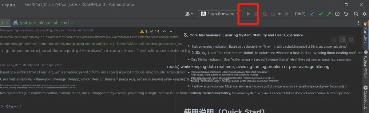
Click the IDE green triangle button in the upper right corner to run, and you can start uploading the firmware and executing the project.
8.3 Modification of Running Configuration
You can configure conf.py and modify or add parameters as needed, for example:
# conf.py example configuration
I2C_INIT_MAX_ATTEMPTS = 3      # Maximum number of device initialization retries
I2C_INIT_RETRY_DELAY_S = 0.5   # Interval between retries (seconds)
ENABLE_DEBUG = True            # Whether to enable debug printing
8.4 Functional Testing
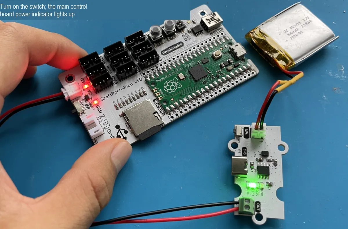
Turn on the VBAT battery power switch located at the bottom of the main control board, and you will see the power indicator lights on both the main control board and the module light up:
- Key Detection: Press different keys and observe the changes in the key status output on the terminal;
- Infrared Transmission: Use an infrared receiving device to verify whether the transmitted data is correct;
- Infrared Reception: Use an infrared remote control to send signals and observe the received data display;
- Display function: Confirm
OLEDcan correctly display the transceiving status and perform automatic clearing.
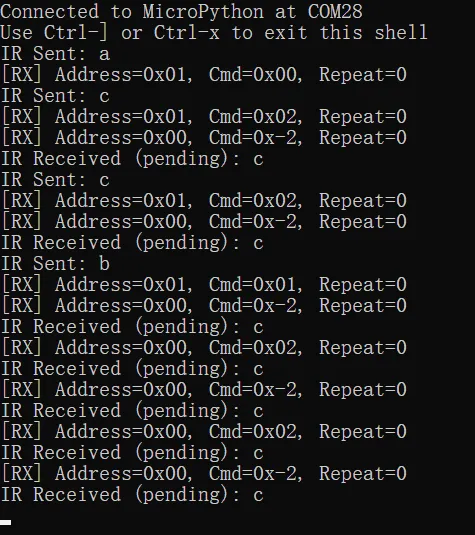
When conf.py is configured unchanged and the hardware connection is normal, the program can run properly.
The terminal output is as follows:
8.5 Debugging and Troubleshooting
- If the function malfunctions, ensure that
ENABLE_DEBUG = True, then view the debug information in the terminal (e. g., "I2C scan result", "IR Sent", etc.); - If
I2Cdevice initialization fails, check the hardware connections, power supply, and pin configuration; - If the infrared communication is abnormal, check the alignment, distance and obstacles of the transceiver module;
- If
OLEDdoes not display, check whether the I2C address is correct and whether theI2Cbus is normal.
9. Sample Program
There are no other reference sample codes for this project, you can directly make modifications in the firmware folder.
10. Notes
- Infrared Communication Related:
- IR333C-based infrared transmitting module requires direct alignment TSOP34138-based infrared receiving module, with no obstacles in between;
- The communication distance is affected by ambient light, and the distance will be shortened in a strong light environment;
- Avoid operating multiple infrared devices simultaneously to prevent signal interference;
TSOP34138The receiving module is sensitive to 38kHz carrier wave, which ensures that the carrier frequency of the transmitting module is accurate.
- Hardware Connection Related:
The I2C address of the PCF8574module must be set to0x27;- IR333C-based infrared transmitting module needs to be connected to a pin that
supports PWMoutput; - The infrared receiving module based on TSOP34138 needs to be connected to a digital input pin;
SSD1306 OLEDmodule's I2C address may be0x3cor0x3d, which will be automatically detected by the system.
- Software Version Related:
MicroPython v1.23.0 or later version must be used;- Debug printing consumes a certain amount of memory, so it is recommended to disable it in formal use scenarios.
- Function Usage Related:
- The automatic sending interval (3 seconds) can be adjusted according to actual needs;
- The display clearing time (5 seconds) can be adjusted according to display requirements;
- The key detection sensitivity can be adjusted via the software debouncing parameters.
11. Version Record
12. Contact the Developer
If you have any questions or need assistance, please contact the developer via the following channels:
📧 Email: 10696531183@qq.com
💻 GitHub: https://github.com/FreakStudioCN
13. Licensing Agreement
In this project, except for machine and other MicroPython official modules (MIT License), all driver and extension codes written by the author are released under the Creative Commons Attribution-NonCommercial 4.0 International (CC BY-NC 4.0) Licensing Agreement.
You are free to:
- Share — copy, distribute the work in any medium or in any form
- Derivative Works — to modify, transform, or create based on the Work
Only the following conditions shall be complied with:
- Attribution — You must give appropriate credit, provide a link to the Licensing Agreement, and indicate if changes were made to the original work. You may do so in any reasonable manner, but not in any way that suggests the licensor endorses you or your use.
- Non-commercial Use — You may not use this work for commercial purposes.
- Proper Citation Method — You may clearly indicate the source in code comments, documentation, demo videos or project descriptions.
Copyright © FreakStudio. All rights reserved.
Appendix 1: Project Source Code Download
https://github.com/FreakStudioCN/GraftPort_MicroPython_Labs/tree/main/infrared_transceiver
Appendix II: Reference Materials for hardware Modules
GraftSense: 8-bit IO Port Expansion Module Based on PCF8574
GraftSense: An Infrared Transmitter Module Based on IR333C
GraftSense - An Infrared Receiving Module Based on TSOP34138
GraftSense 0.96-inch SSD1306 OLED Module
GraftSense-SY7656 Lithium Battery Charge-Discharge Module
GraftPort - Raspberry Pi Pico Expansion Board (Open Edition Template Files)
Version Record
Document Version | Date of Revision | Modifier | Revised Content |
V1.0.0 | 2025-11-03 | Hou Junhan | Draft the initial version of the document. |
V1.1.0 | 2026-01-04 | Li Zisheng | Final version. |