Contents
- I. Module Introduction
- II. Introduction to Main Chips
- 2.1 Chip Overview
- 2.2 Pin Definition
- 2.3 Functional Block Diagram
- 2.4 Performance Parameters
- 2.5 Reference Circuit
- 2.6 Chip Configuration
- 2.7 Communication Interfaces and Related Protocols
- 2.8 PCB Routing Notes
- III. Circuit Engineering
- 3.1 Circuit Source Engineering
- 3.2 Module Usage Instructions
- 3.3 Application Experiment
- IV. Drivers
- 5. BOM & Recommended Alternative Parts
- VI. Revision History
- VII. Relevant Materials
- 7.1 Chip Datasheet
- 7.2 Unique Icons for PCB Silk Screen
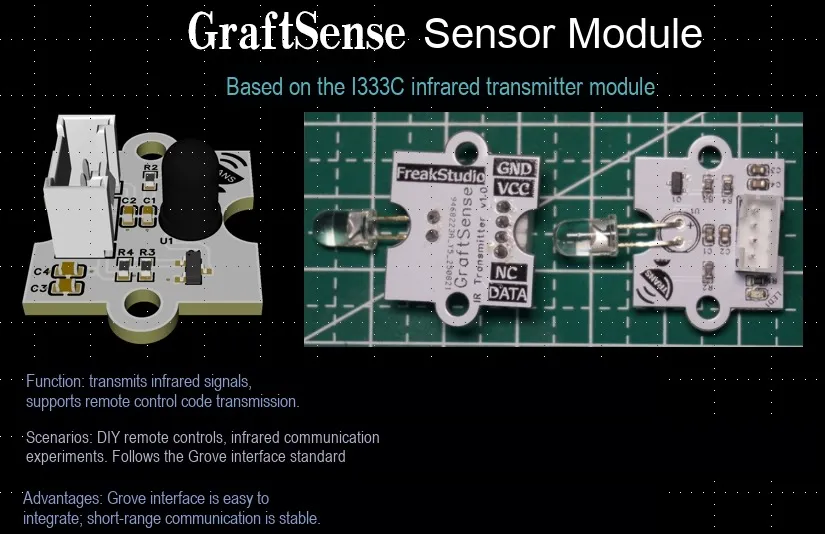
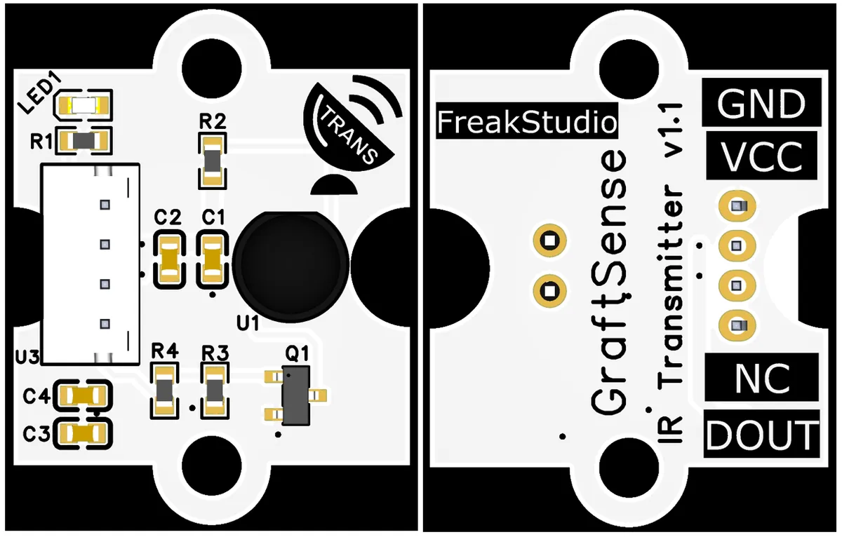
I. Module Introduction
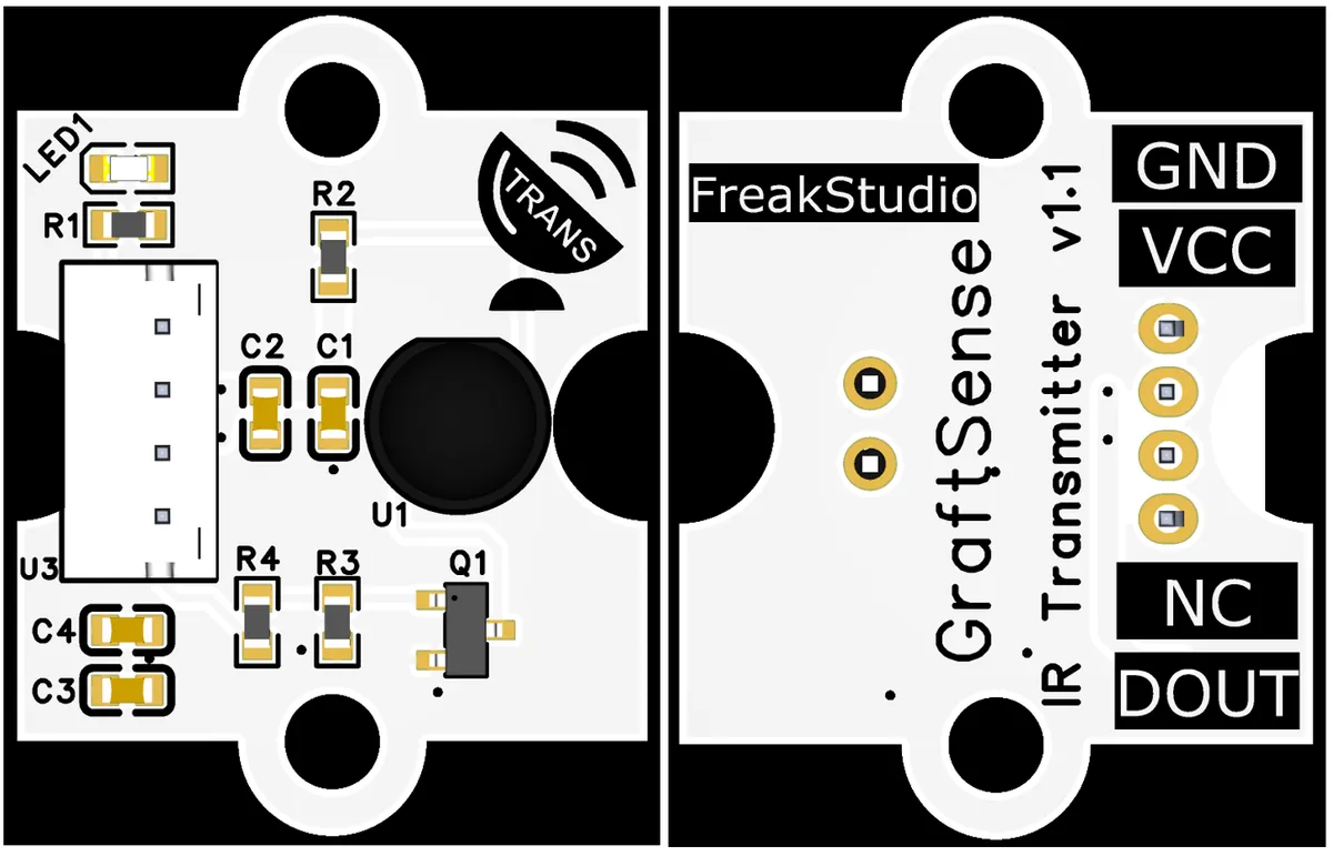
IR Transmitter Module Based on IR333C takes IR333C infrared emitting diode as the core, integrates a driving circuit and a filtering unit, can emit infrared light with a wavelength of 850–950nm (typically 940nm), supports 38kHz carrier modulation, operates at a voltage of 3–5V, and has a transmission distance of approximately 1.3 meters (at 5V).The module is equipped with GND, VCC, DOUT and other pins. It connects to the main control device (such as Arduino, microcontroller) via digital signals (high-level triggered transmission), and is applicable to scenarios including infrared remote control (TV / air conditioner), non-contact sensing, short-range infrared data transmission, featuring low power consumption, fast response and high reliability.
II. Introduction to Main Chips
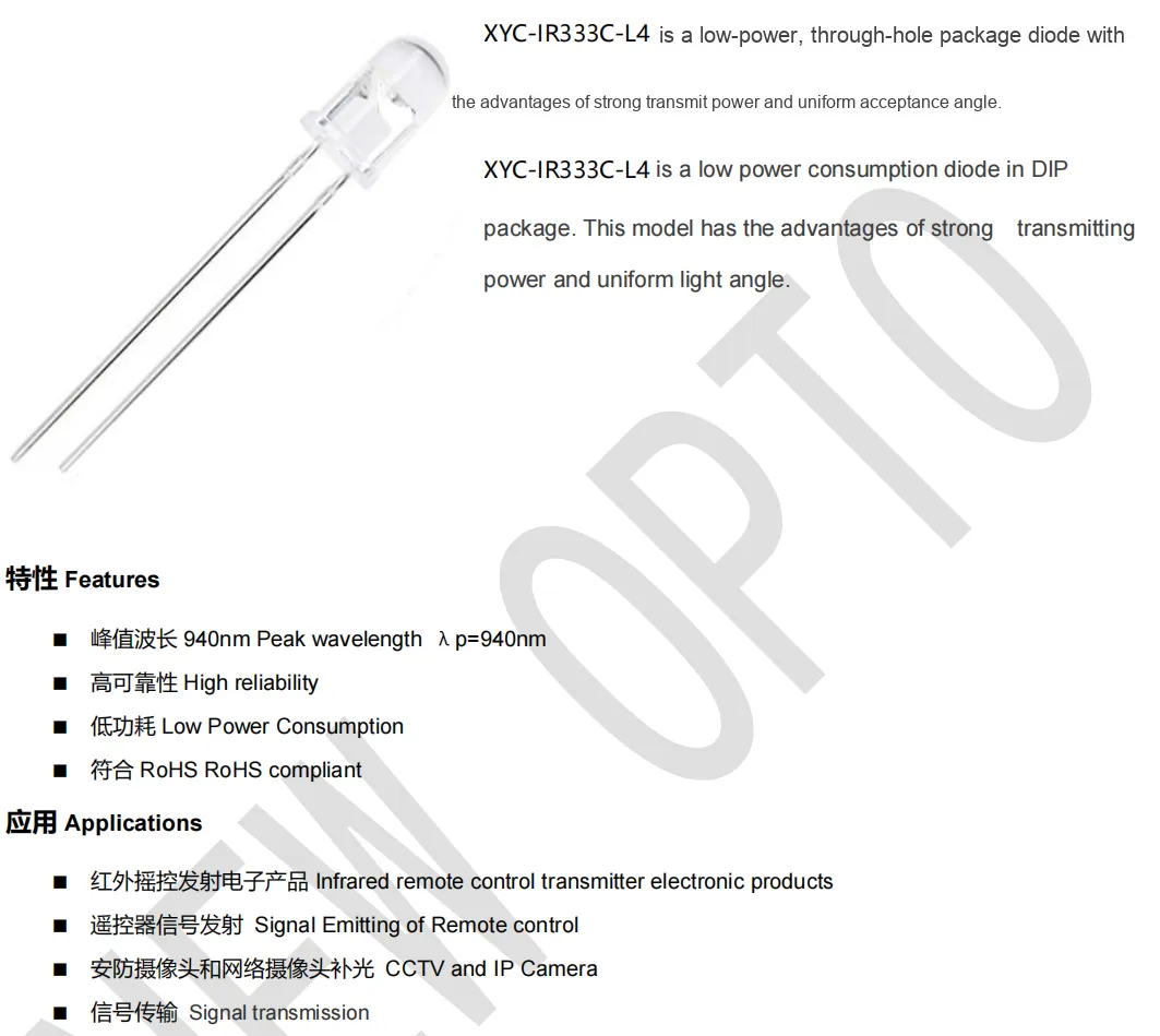
The core component is IR333C infrared emitting diode.
2.1 Chip Overview
2.2 Pin Definition
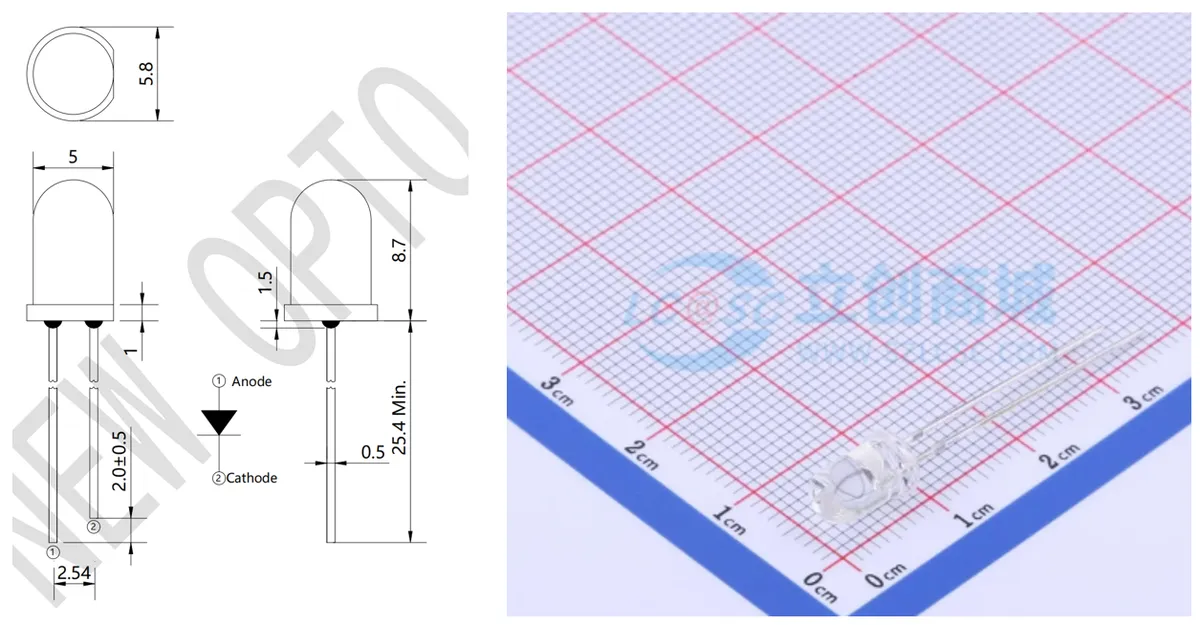
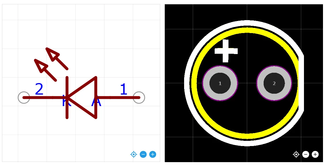
IR333C The pins of the infrared emitting diode are similar to those of a common diode: Pin 1 is the anode and Pin 2 is the cathode.
2.3 Functional Block Diagram
None.
2.4 Performance Parameters
2.4.1 Electrical Parameters
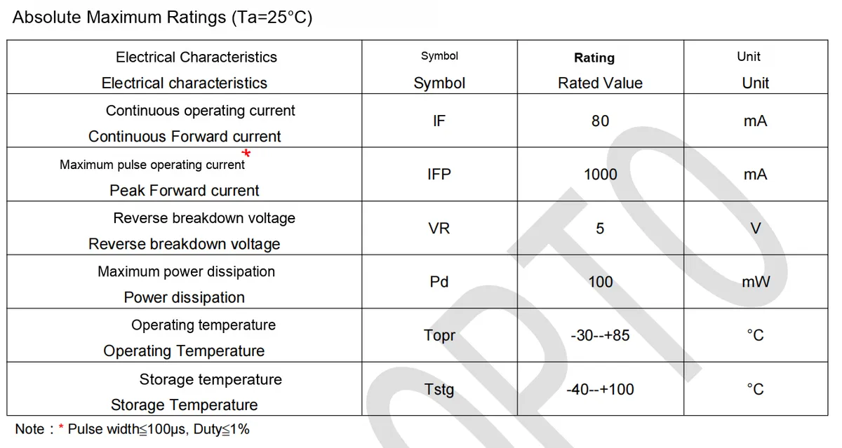
- Continuous forward current (
I<sub>F</sub>): max. 80mA, which refers to the upper limit of the forward current that the device can operate continuously for a long time; exceeding this value may easily cause damage to the device. - Maximum Pulse Operating Current (
IFP): Up to 1000mA at maximum, subject to the constraints specified in the note (pulse width ≤ 100μs, duty cycle ≤ 1%). This is only permitted in scenarios with short pulses and low duty cycles; otherwise, the current must be reduced to avoid overloading. - Reverse Breakdown Voltage (
VR): Maximum 5V. If the reverse voltage applied exceeds this value, the device may break down, so the reverse voltage shall be limited during design. - Maximum Power Dissipation (
Pd): Max. 100mW. Excessive power dissipation will cause overheating and damage to the device, so power consumption must be controlled through coordinated adjustment of current and voltage.
2.4.2 Optoelectronic Properties
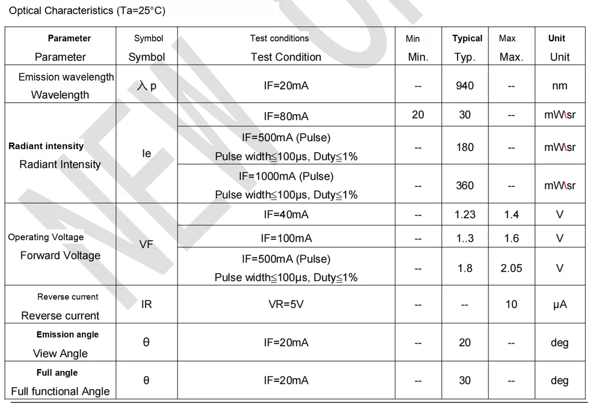
The following is an interpretation of the key optoelectronic characteristic parameters of IR333C infrared emitting diode:
- Emission Wavelength (
λp)- Test Conditions:
I_F= 20mA - Typical value: 940nm
- Interpretation: This is the core wavelength parameter of infrared light, which falls within the near-infrared range (850–950 nm) and matches the spectral response range of most infrared receiving devices, ensuring the compatibility of signal reception.
- Test Conditions:
- Radiant intensity (
I_e): It characterizes the "power" of infrared light emission, which directly affects the transmission distance and signal stability, and is strongly correlated with the operating current and mode. - Continuous operation mode (
I_F= 80mA): Minimum 20 mW/sr, typical 30 mW/sr, suitable for conventional short-distance signal transmission (e. g., infrared remote control within 1 meter). - Pulse operation mode (subject to the requirements of "pulse width ≤ 100μs, duty cycle ≤ 1%"):
I_F= 500mA, typical value is 180mW/sr;I_F= 1000mA, typical value is 360mW/sr.- The pulse mode boosts radiation intensity via short-duration high current to extend the transmission distance (e. g., over 1.3 meters), yet pulse parameters must be strictly controlled to prevent device overheating.
- Forward Operating Voltage (
V_F): It refers to the forward voltage drop when the infrared tube is conducting, which is a key parameter for driving circuit design.I_F= 40mA: typical 1.23V, maximum 1.4V;I_F= 100mA: typically 1.3V, maximum 1.6V;
- Pulse mode (
I_F= 500mA): Typical value is 1.8V, maximum value is 2.05V. During design, the supply voltage should be matched according to the operating current to ensure normal turn-on of the device and reasonable power consumption of the driving circuit. - Reverse Current (
I_R)- Test Conditions:
V_R= 5V (Reverse Voltage) - Maximum value: 10μA
- Interpretation: The extremely low reverse leakage current indicates that the device has excellent reverse insulation performance, which can reduce the interference of reverse voltage on the circuit and improve operational stability.
- Test Conditions:
- Transmission angle parameter: It defines the effective coverage range of infrared light and affects the "alignment accuracy" requirement during use.
- View Angle (Emission Angle):
When I_F= 20mA, the typical value is 20°(concentration range of the main beam); - Full Functional Angle:
I_F= 20mA, typically 30°(the maximum angle range for stable signal transmission). The 30° full functional angle reduces alignment requirements during use, making it suitable for non-precision aiming scenarios (such as infrared remote control and area sensing).
- View Angle (Emission Angle):
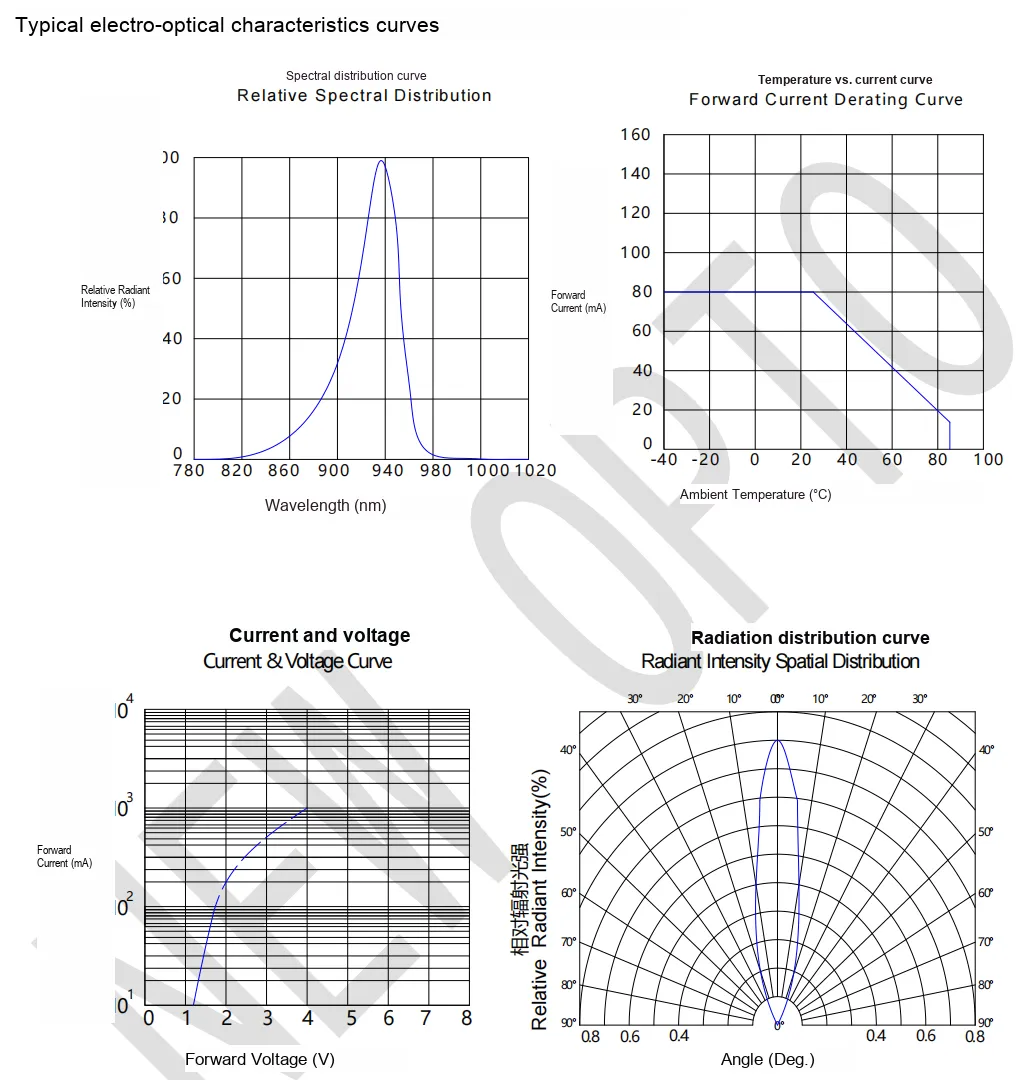
- Spectral distribution characteristic curve: The wavelength corresponding to the peak of the curve is approximately 940 nm, indicating that
IR333Chas infrared radiation energy highly concentrated around 940 nm, which verifies the unimodality and concentration of its emission wavelength and ensures the optimal infrared signal transmission efficiency at this wavelength. - Temperature vs. Current Curve: As the ambient temperature rises, the allowable forward operating current (derating current) of the device continues to decrease. For example, it can approach 80mA (the rated continuous operating current) at 25°C, and derates to approximately 20mA at around 80°C, which reflects the constraint of temperature on the current-carrying capability of the device. Designs shall take ambient temperature into consideration to avoid overcurrent damage.
- Current & Voltage Curve: Forward voltage (
VF) and forward current (IF) exhibit a non-linear growth relationship: the current rises slowly at low voltages, and increases rapidly once the voltage exceeds a specific value (e. g., 2V), which conforms to the volt-ampere characteristic of diodes that "current grows exponentially with voltage after forward turn-on", and reflects the electrical characteristic law ofIR333Cas an infrared emitting diode. - Radiation intensity distribution characteristic curve: The radiation intensity presents a symmetric "bell-shaped" distribution centered at 0°(directly in front), with the highest relative radiation intensity at 0° and gradual attenuation within the range of ±30°, which intuitively demonstrates the emission angle characteristic of the device, and echoes the parameter of "typical full-function angle of 30°", indicating that the infrared radiation directly in front is the strongest while the radiation capability in large-angle regions is weakened.
2.5 Reference Circuit
None.
2.6 Chip Configuration
None.
2.7 Communication Interfaces and Related Protocols
None.
2.8 PCB Routing Notes
None.
III. Circuit Engineering
3.1 Circuit Source Engineering
To obtain the circuit source project, please follow the official account [Freak Embedded]
3.2 Module Usage Instructions
The schematic diagram of this module is shown below:
SCH_Schematic1_Infrared Emitter Module Based on IR333C_v1.1_2025-09-18.pdf 1.3 MB
This module provides a digital input interface:
- Digital Input (
DOUT): This is the digital control input terminal of the module, used to receive high and low level signals output by external main control devices (such as single-chip microcomputers and microcontrollers). When a high level is input toDOUT, the drive circuit powers on the infrared emitting diode (IR333C) to emit infrared light; when a low level is input toDOUT, the infrared emitting diode stops emitting. Through this interface, digital signals such as encoded infrared commands (e. g., remote control signals) and sensing trigger signals can be converted into the "on/off" action of infrared light, realizing infrared communication, remote control or sensing functions.
The core circuit of the module is the infrared transmitting circuit: with IR333C infrared emitting diode (U1) as the core, it is driven by S8050 triode (Q1). VCC supplies power to R2 (62Ω) to U1; the base of the triode Q1 receives the R4 (4.7kΩ) via DATA control signal, and R3 (10kΩ) is the base pull-down resistor (to ensure reliable cut-off of Q1 when there is no input). When DATA is at high level, Q1 turns on, and IR333C is powered on to emit infrared light;When DATA is at a low level, Q1 is cut off, the infrared emitting diode stops emitting light, thus realizing the conversion from "digital signal to infrared light".
3.3 Application Experiment
Here, we use the GraftPort-RP2040 development board for testing, and connect the IR333C-based infrared transmitting module and the TSOP34138-based infrared receiving module to communicate with the main controller via the DIO interface.
Here, we first use the HY2.0-4P connection cable to connect the module to the GraftPort-RP2040 development board's DIO0 and DIO1 interfaces:
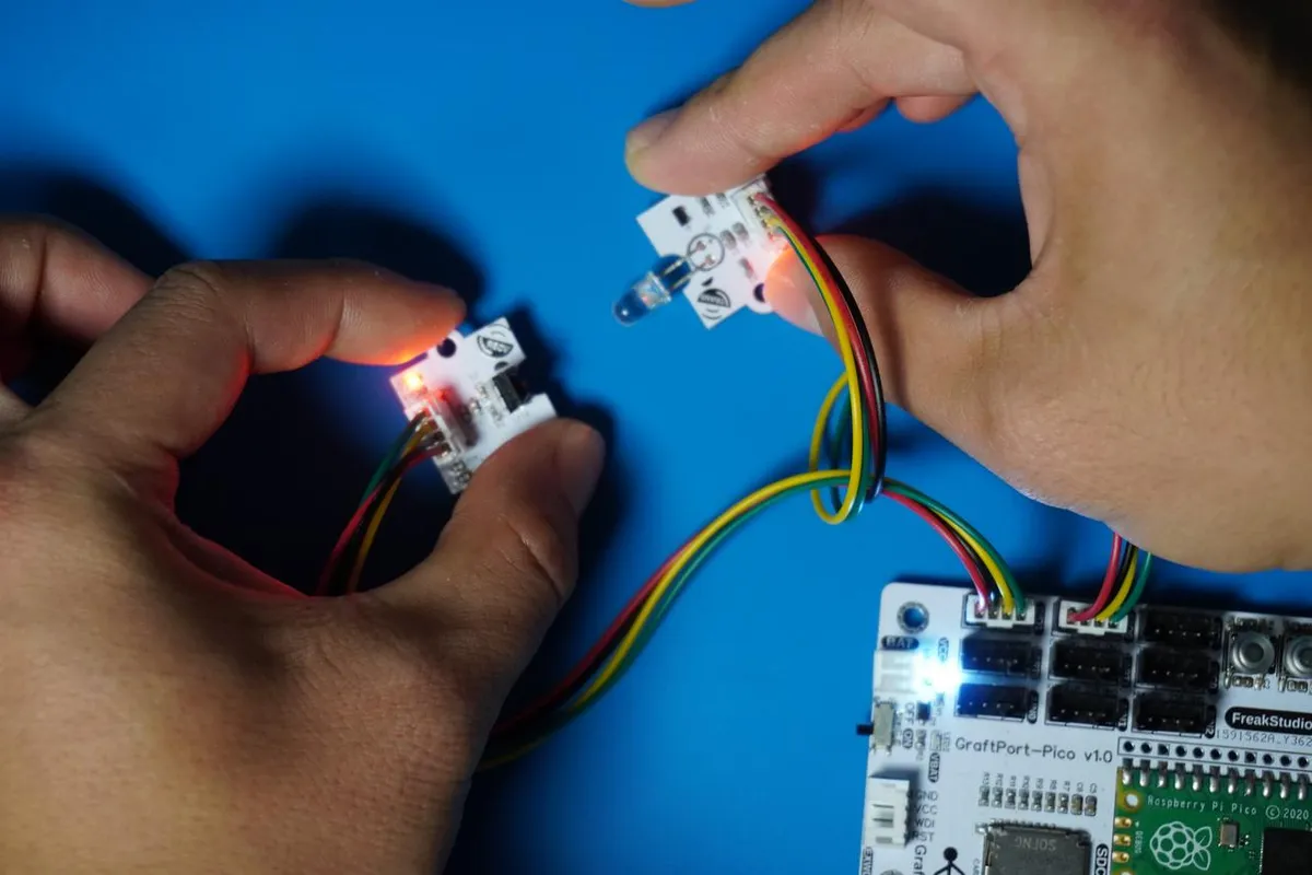
The module connections are shown in the following table:
IR333C-based infrared transmitting module:
Development Board Pins | Module Pins | Description |
Pin 6 |
| Infrared signal transmission output pin |
Pin 7 |
| - |
Infrared receiving module based on TSOP34138:
Development Board Pins | Module Pins | Description |
Pin 14 |
| - Infrared signal receiving input pin |
Pin 15 |
| - |
Here, we need to search for the relevant driver packages on uPyPI: https://upypi.net/zh/
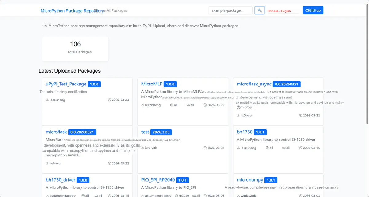
Enter irtranslation_driver to search, and the following will be displayed:
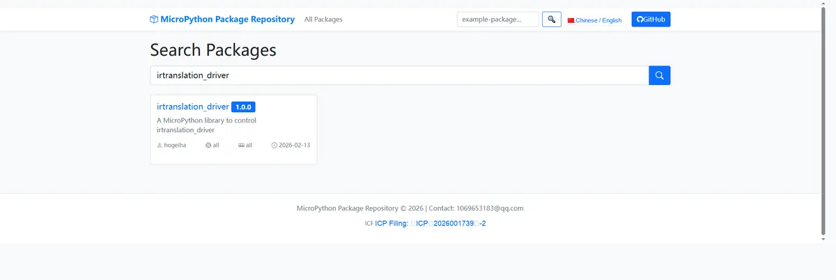
Click to copy the local installation command:
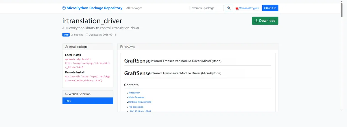
Here, we can use the mip tool to import module driver library code. Below are the usage commands for the mpremote tool:
mpremote mip install github:FreakStudioCN/GraftSense-Drivers-MicroPython/communication/irtranslation_driverHere, before conducting communication, we need to align the infrared transceiver units between the modules as precisely as possible:
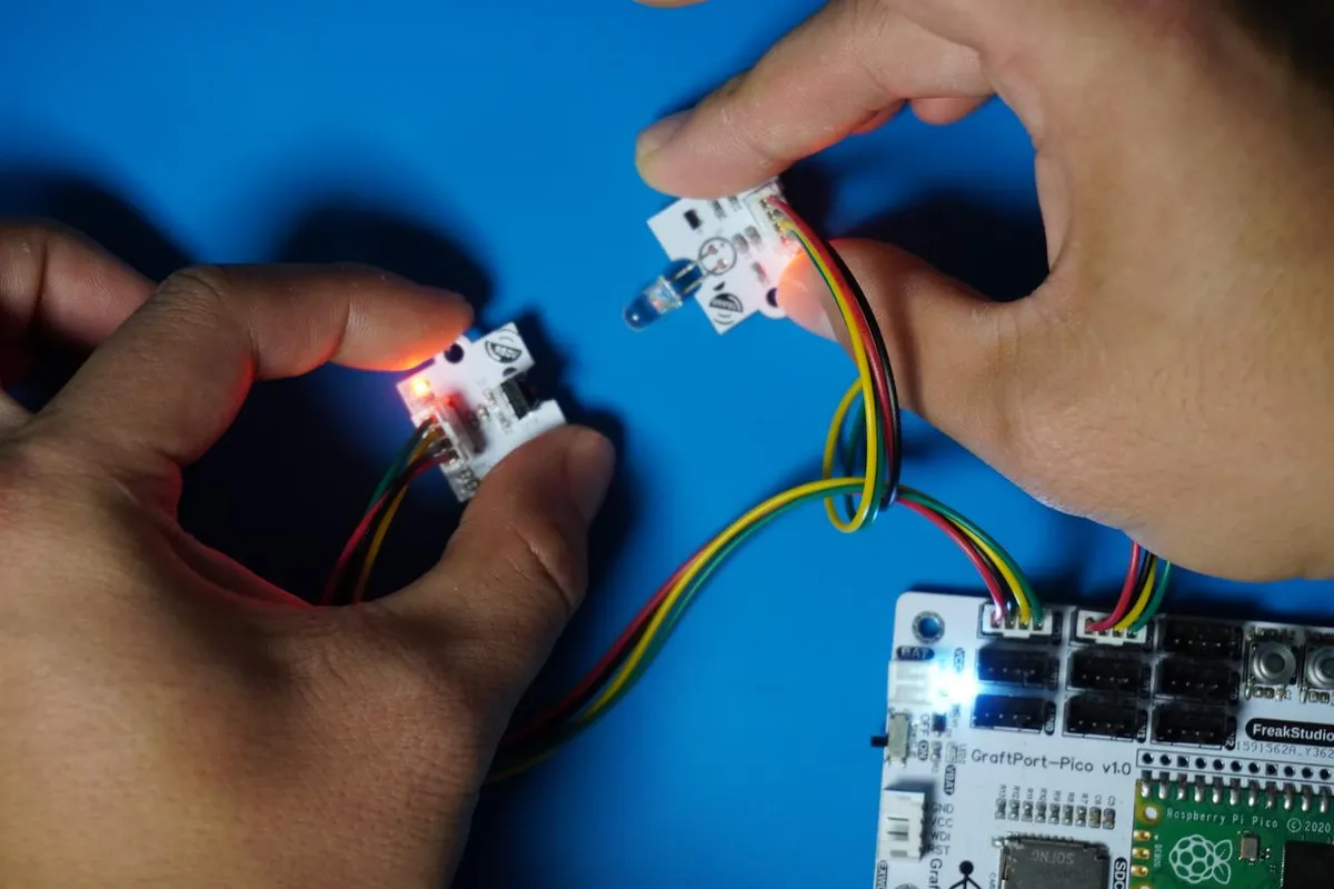
Import the IR transceiver driver - MicroPython driver code, then copy the following main.py code into our project:
# Python env   : MicroPython v1.23.0
# -*- coding: utf-8 -*-
# @Time    : 2025/8/26 10:11 PM
# @Author  : 缪贵成
# @File    : main.py
# @Description : Test file for the nec_16 protocol on the Raspberry Pi Pico

# ======================================== Import Modules =========================================

import time
from machine import Pin
from ir_tx.nec import NEC
# nec_16 has three parameters in the callback function
from ir_rx.nec import NEC_16

# ======================================== Global Variables ============================================

# ======================================== Functions ============================================

# If using nec_8, pass variable-length arguments; this is nec_16

def ir_callback(addr: int, cmd: int, repeat: bool) -> None:
    """
    NEC protocol receive callback function (3-parameter version).

    Args:
        addr (int): Received address
        cmd (int): Received command code
        repeat (bool): Whether this is a repeat code (True = yes, False = no)

    Notes:
        The callback is called by the NEC receive module and is not ISR-safe.
        Output the received data to the serial port.

    ==========================================

    NEC IR signal receive callback (3-parameter version).

    Args:
        addr (int): Received address
        cmd (int): Received command
        repeat (bool): Repeat flag (True = yes, False = no)
    Notes:
        Called by NEC IR receiver. Not ISR-safe.
        Prints received data to REPL.
    """
    print(f"[RX] Address=0x{addr:04X}, Cmd=0x{cmd:02X}, Repeat={repeat}")

# ======================================== Custom Classes =============================================

# ======================================== Initialization configuration ===========================================

# Power-on delay of 3 s
time.sleep(3)
print("FreakStudio:Infrared transceiver test")

# Transmitter connected to GP6
TX_PIN = Pin(6, Pin.OUT)
# Receiver connected to GP14
RX_PIN = Pin(14, Pin.IN)
# 38kHz transmit
ir_tx = NEC(TX_PIN, freq=38000)
# Receive NEC
ir_rx = NEC_16(RX_PIN, ir_callback)
print("[System] Ready... TX=GP6, RX=GP14")

# ========================================  Main Program  ===========================================
while True:
    print("[TX] Sending NEC signal...")
    # Address=0x10, command=0x20
    ir_tx.transmit(0x10, 0x20)
    time.sleep(2)
Burn the code, open the terminal, and use the mpremote tool to connect to the main controller; the output is as follows:
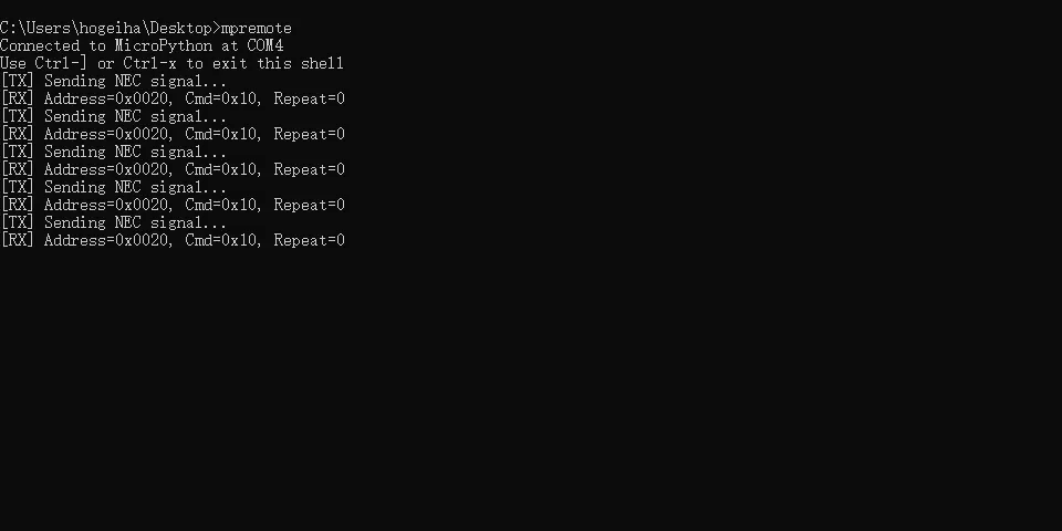
It can be seen that when the infrared receiving module based on TSOP34138 receives the data sent by the infrared transmitting module based on IR333C, it will trigger the callback function to print[RX]content.
IV. Drivers
irtranslation_driver.zip 27 KB
Only the NEC protocol will be tested as follows:
irtranslation.rar 29 KB
For more remaining protocols, you can refer to the following for reference:
micropython_ir-master.rar 897 KB
You can also go through this document to understand the driver code of the infrared transceiver module:
Lesson 3: How to Use AI Tools to Quickly Read Unfamiliar Code
5. BOM & Recommended Alternative Parts
None.
VI. Revision History
Document Version | Date of Revision | Modifier | Modify Content |
v1.0 | 2025.8.20 | Miu Guicheng | Initialize the document |
v1.1 | 2025-09-18 | Li Zisheng | Added Section 2.8 PCB Routing Notes Revised Section 3, Instructions for Circuit Source Engineering and Module Usage, and added a secondary heading: 3.1 Circuit Source Engineering, 3.2 Module Usage Instructions, 3.3 Application Experiments The BOM sheet has not been finally checked, the driver has not been re-verified, and the 3.3 application experiment Not yet specified. |
v1.2 | 2025-12-29 | Li Zisheng | Added application experiments and production files |
v1.3 | 2025-12-31 | Xin Ruili | Create an open version of the document based on the internal document version v1.2. |
v1.4 | 2026-03-29 | Xin Ruili | Modified the application experiment section. |
VII. Relevant Materials
7.1 Chip Datasheet
XYC-IR333C-L4 Emitter Datasheet.pdf 763 KB
7.2 Unique Icons for PCB Silk Screen