Contents
- I. Module Introduction
- II. Introduction to Main Chips
- 2.1 Chip Overview
- 2.2 Pin Definition
- 2.3 Functional Block Diagram
- 2.4 Performance Parameters
- 2.5 Reference Circuit
- 2.6 Chip Configuration
- 2.7 Communication Interfaces and Related Protocols
- 2.8 PCB Routing Notes
- 3. Instructions for Circuit Engineering and Module Usage
- 3.1 Circuit Source Engineering
- 3.2 Module Usage Instructions
- 3.3 Application Experiment
- IV. Drivers
- 5. BOM & Recommended Alternative Parts
- VI. Revision History
- VII. Relevant Materials
- 7.1 Chip Datasheet
- 7.2 Unique Icons for PCB Silk Screen
I. Module Introduction
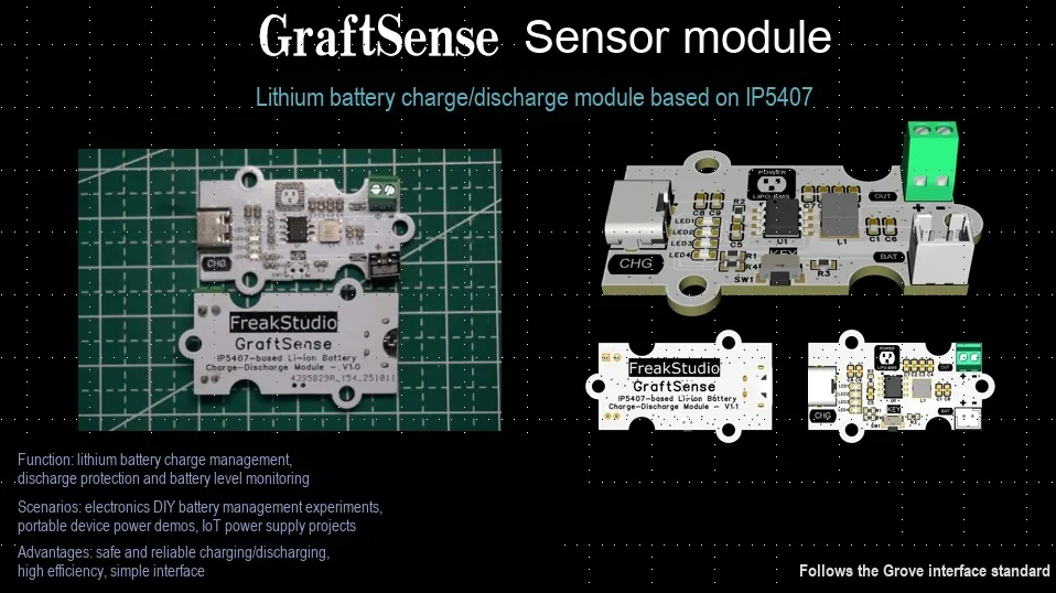
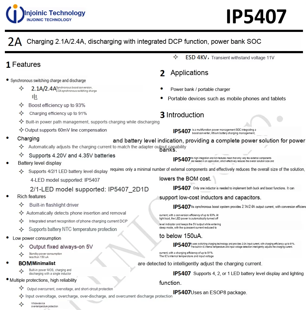
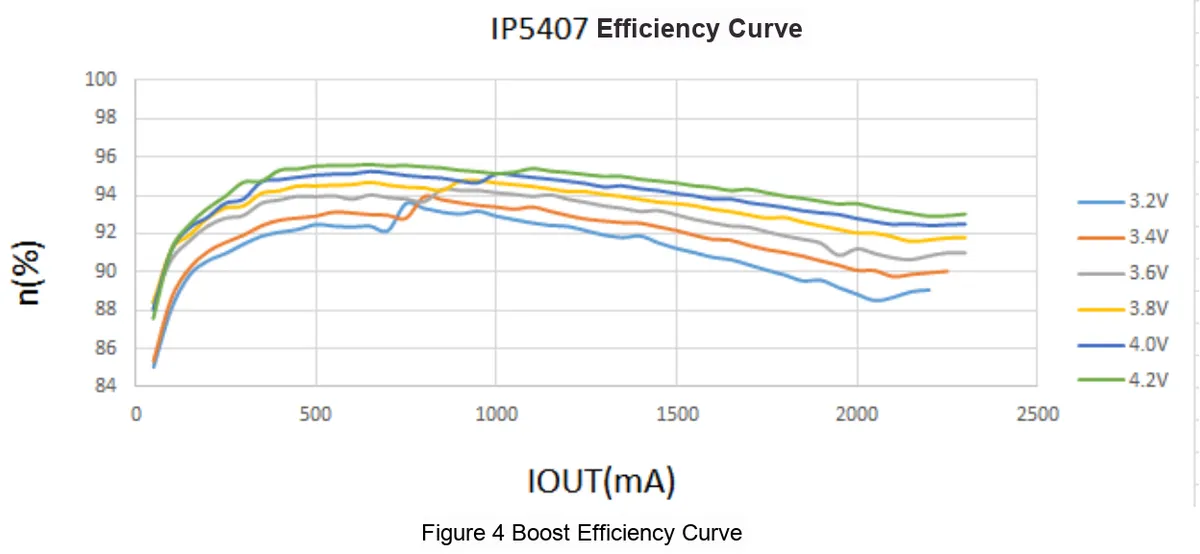
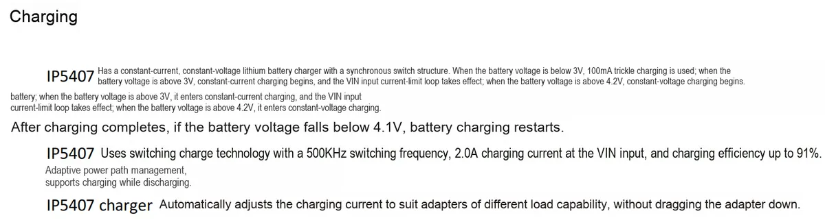
Lithium Battery Charge-Discharge Module Based on IP5407 Based on Injoinic IP5407 chip, which is a multi-functional power supply SOC integrating boost conversion and lithium battery charge management. It supports 2A charging, 2.1A/2.4A synchronous boost discharging (with a boost efficiency of up to 93% and a charging efficiency of up to 91%), and features 4/2/1 LED power indicators and multiple protection functions (output overcurrent/overvoltage/short circuit, input overvoltage/overdischarge, etc.).The module is equipped with Type-C charging port, lithium battery connection terminal and discharging interface, which can realize the management of lithium battery charging and discharging as well as the visualization of power status. It is suitable for scenarios such as mobile power supplies and portable electronic devices, and provides an efficient and safe power management solution for lithium battery systems.
II. Introduction to Main Chips
2.1 Chip Overview
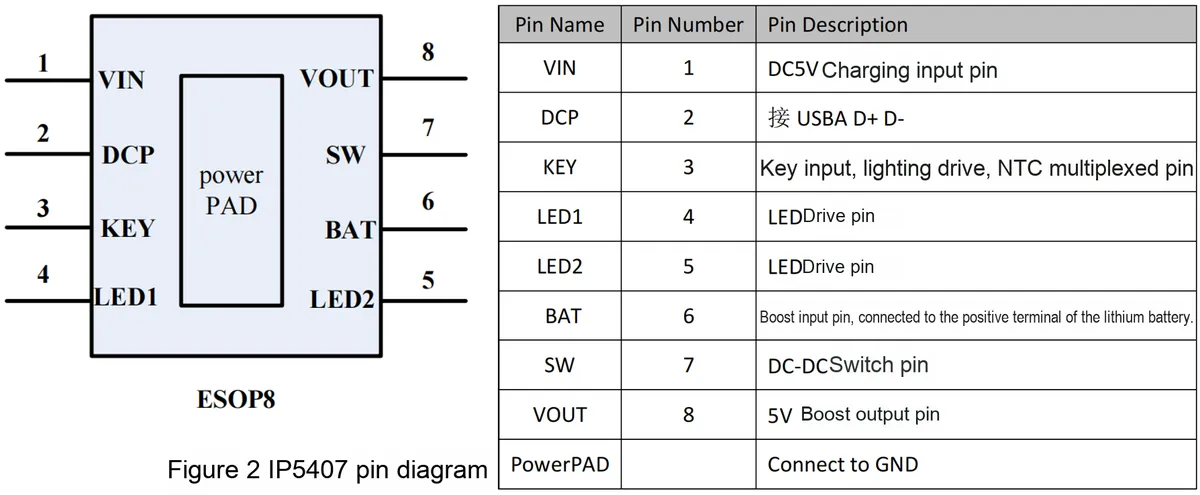
2.2 Pin Definition
2.3 Functional Block Diagram
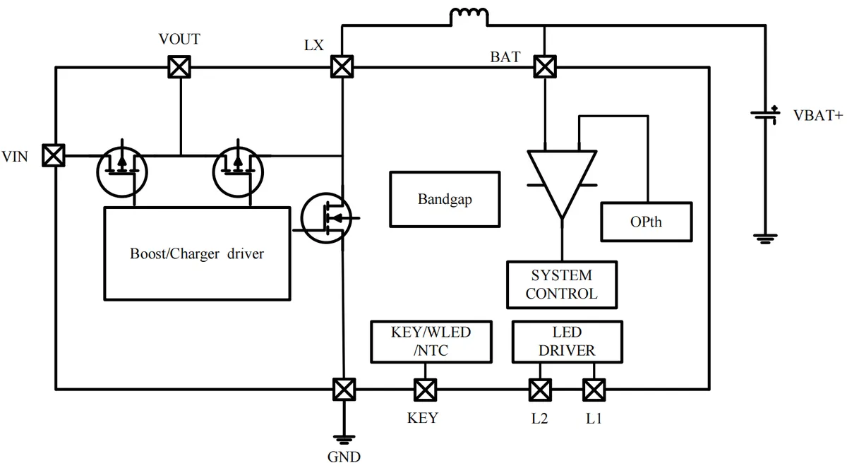
This IP5407 chip features a highly integrated internal structure, where various modules work in coordination to implement charge-discharge management, power level display and protection functions, as detailed below:
- Boost / Charger Driver Module (
Boost/Charger driver): It controls the internal powerMOStubes to realize synchronous switching charging and discharging, and supports 2.1A/2.4A synchronous step-up as well as 2.0A synchronous switching charging, serving as the core drive unit for energy conversion. - Power
MOStransistor array: Controlled by the driver module, it switches the current paths of nodes such asVIN,LX, andBAT, and works with a single inductor to achieve step-down/step-up functions, simplifying peripheral circuit design. - Bandgap Reference (
Bandgap): It provides a stable voltage reference, ensures the accuracy of voltage detection and control, and lays a foundation for charge and discharge voltage regulation. - Detection and Operation Module (
OPth): It implements the detection and comparison of battery voltage and current through operational amplifiers, providing data support for system control. - System Control Unit (
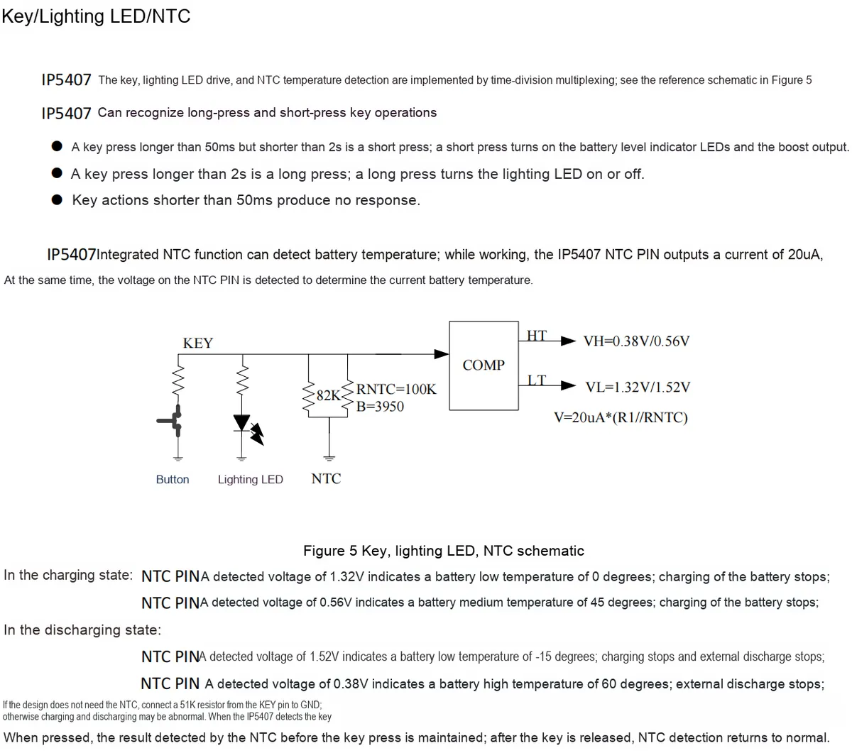
SYSTEM CONTROL): It coordinates the logic of each module, and implements centralized scheduling of charging strategies (automatic adapter adaptation, charging while discharging), discharging management, power calculation, and multiple protections (overcurrent, overvoltage, short circuit, overtemperature, etc.). KEY/WLED/NTCModule: Integrates key input, lightingLEDdriving, and battery temperature (NTC) detection functions to realize human-machine interaction, auxiliary lighting and temperature protection.LEDdriver module (LED DRIVER): ControlsL1andL2pins to drive 4/2/1LEDsfor visual power level indication.
In addition, the external inductor and the battery (VBAT+) are connected via the BAT terminal, and cooperate with the internal module to complete energy storage and conversion, finally realizing a complete power management solution for power bank products.

2.4 Performance Parameters
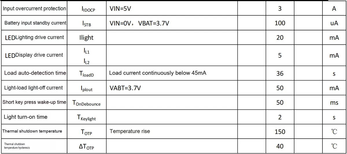
2.5 Reference Circuit
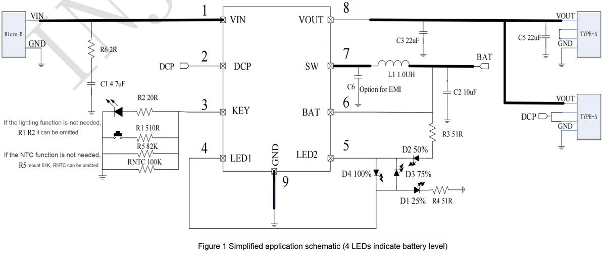
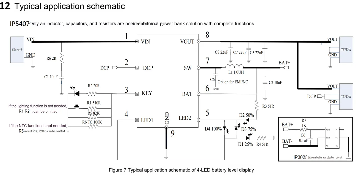
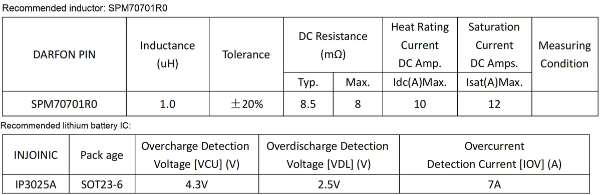
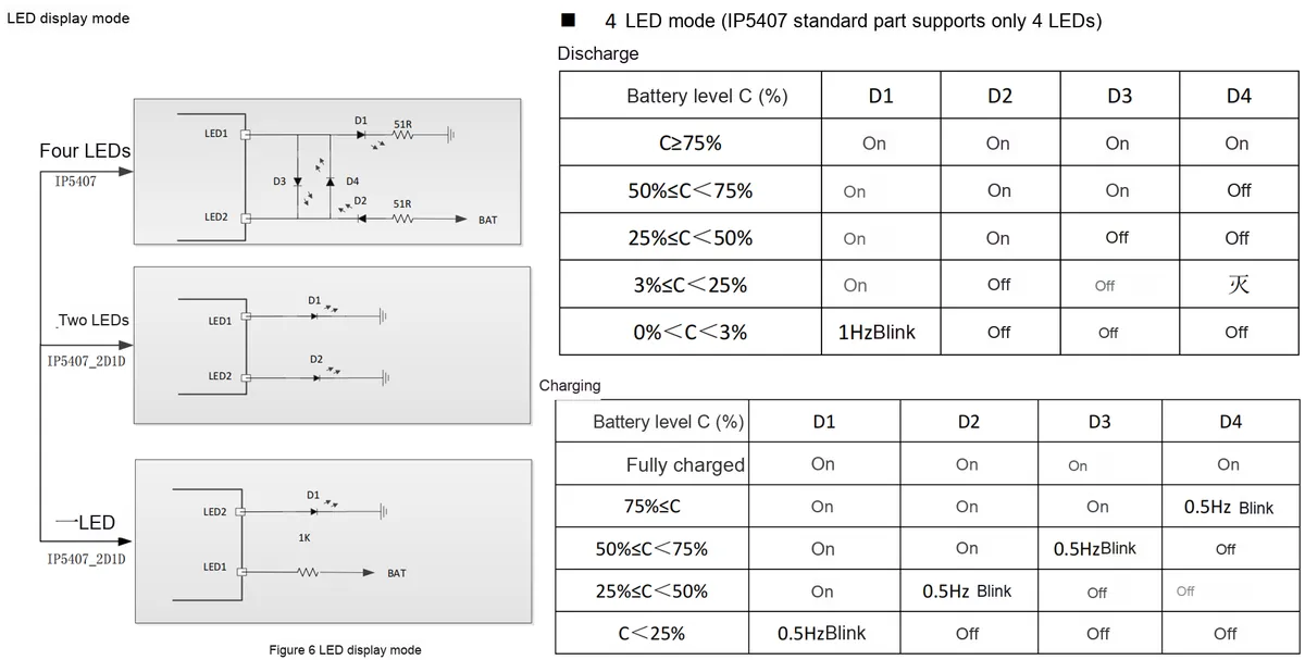
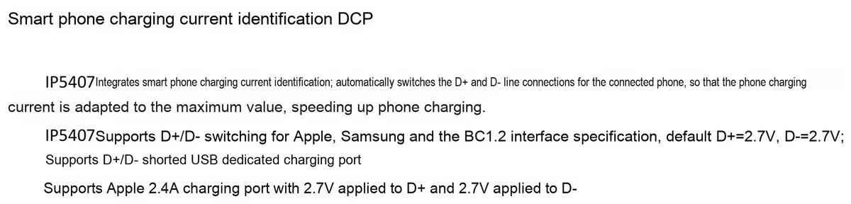
2.6 Chip Configuration
2.7 Communication Interfaces and Related Protocols
None.
2.8 PCB Routing Notes
None.
3. Instructions for Circuit Engineering and Module Usage
3.1 Circuit Source Engineering
To obtain the circuit source project, please follow the official account [Freak Embedded]
3.2 Module Usage Instructions
The schematic diagram of this module is shown below:
SCH_IP5407-Based Lithium Battery Charge/Discharge Module_v1.1_2025-11-24.pdf 3.2 MB
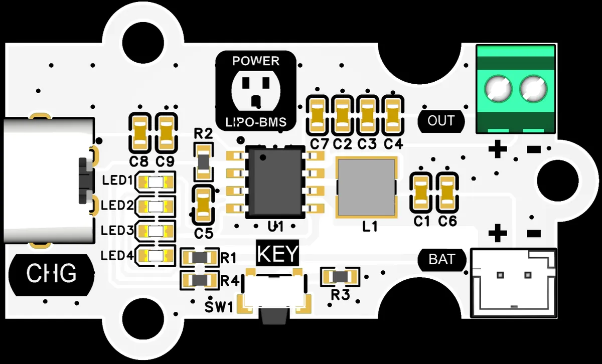
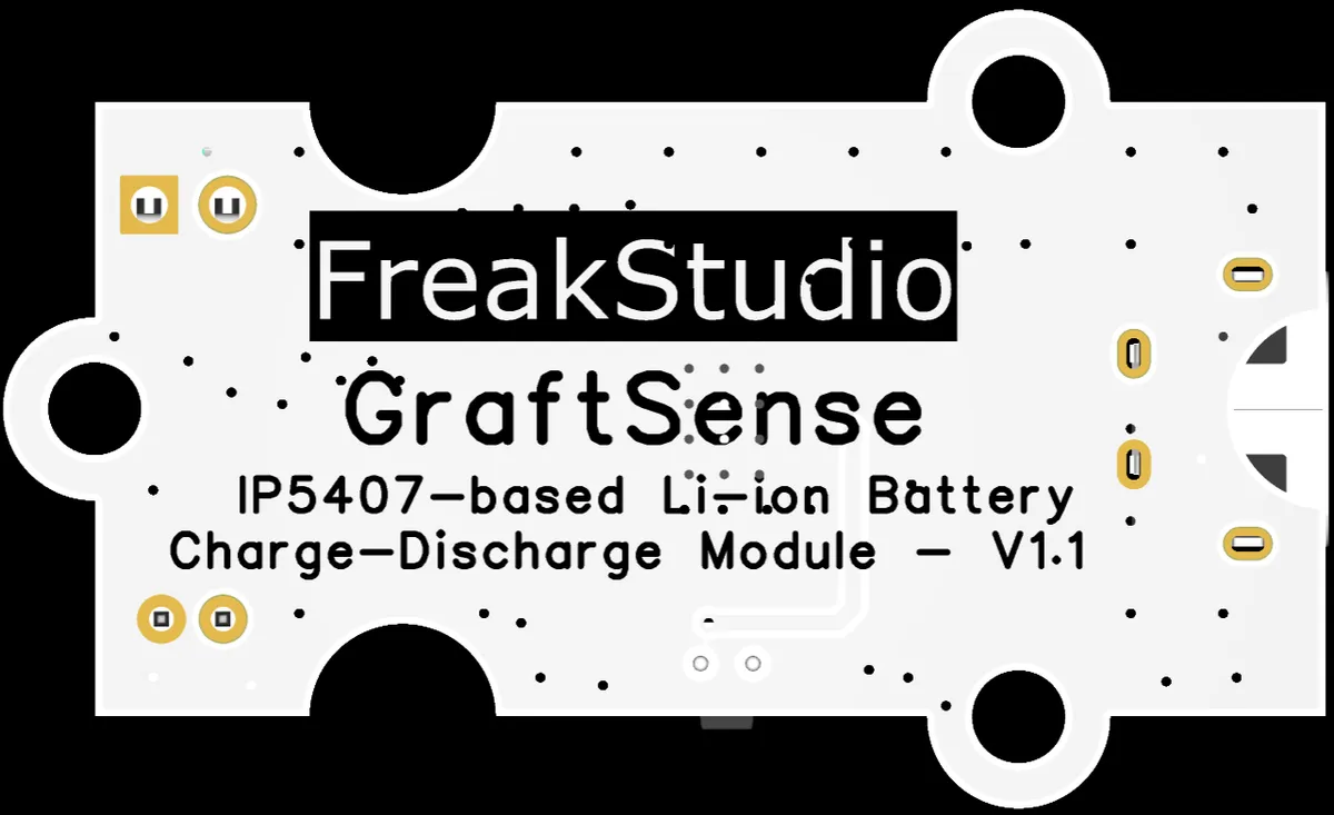
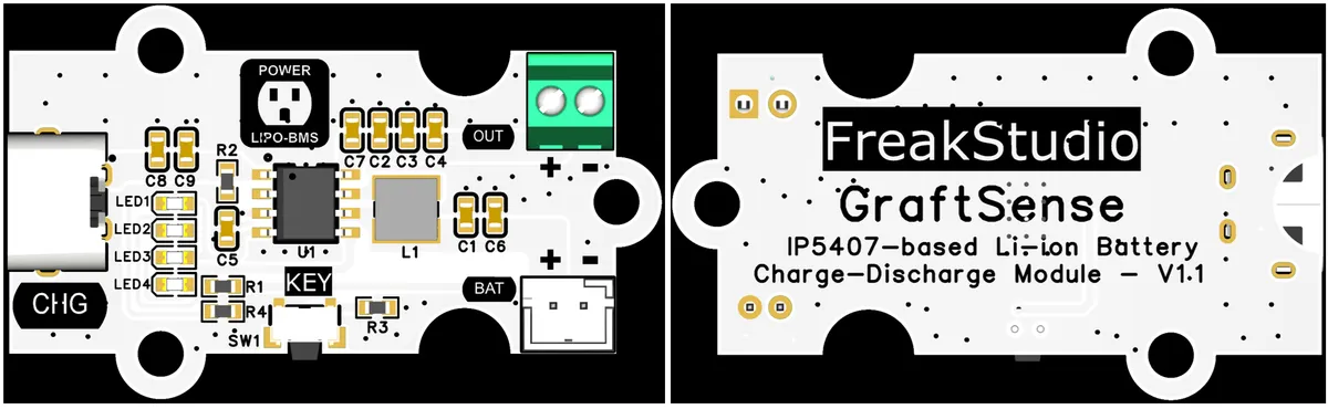
This module is designed specifically for single-cell lithium batteries, compatible with 4.20V and 4.35V batteries; it is equipped with 1 Type-C charging port, 1 5V/2.1A external power supply port and 1 lithium battery charging port, covering the full-process requirements of charging and discharging.
This module provides the following interfaces and functions:
CHGInterface: Charging is realized via theType-Cinterface;BATInterface: Compatible with connection to 3.7V polymer lithium batteries;OUTInterface: Outputs 5V voltage for external power supply.
The module supports 4 LEDs (LED1 to LED4) for power level indication, which correspond to the four power ranges of the battery respectively to visually display the remaining power.
Button KEY is used to control the step-up power supply:
- Short press (the key is pressed for 50ms~2s): Turn on the power indicator light and start the boost output;
- Key press duration ≤50ms or ≥2s: No response.
3.3 Application Experiment
Here, we use a lithium battery charge-discharge module based on the IP5407 connected to the battery for power supply.
Press BAT button to check the battery level
The module connections are shown in the following table:
Lithium Battery | Module Pins | Description |
|
| - |
|
| - |
- |
| 5V/2.1A External Power Supply Interface |
- |
| 5V/2.1A External Power Supply Interface |
This module does not require driver code.
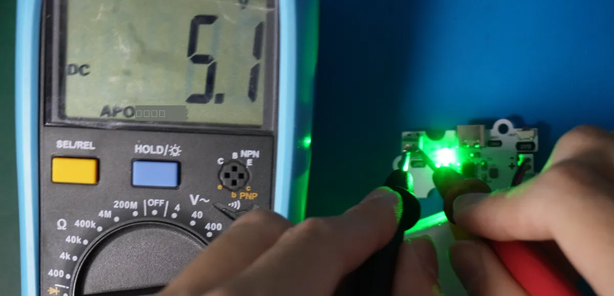
The terminal block outputs 5V
IV. Drivers
None.
5. BOM & Recommended Alternative Parts
None.
VI. Revision History
Document Version | Date of Revision | Modifier | Modify Content |
v1.0 | 2025-11-24 | Li Zisheng | Initialize the document The BOM sheet has not been finally checked, the driver has not been re-verified, and the 3.3 application experiment Not yet specified. |
v1.1 | 2025-12-29 | Li Zisheng | Added application experiments and production files |
v1.2 | 2025-12-31 | Xin Ruili | Create an open version of the document based on the internal document version v1.1. |
VII. Relevant Materials
7.1 Chip Datasheet
C2890537_Battery Management_IP5407_Datasheet_WJ93090.PDF 880 KB
7.2 Unique Icons for PCB Silk Screen