Contents
- I. Module Introduction
- II. Introduction to Main Chips
- 2.1 Chip Overview
- 2.2 Pin Definition
- 2.3 Functional Block Diagram
- 2.4 Performance Parameters
- 2.5 Reference Circuit
- 2.6 Chip Configuration
- 2.7 Communication Interfaces and Related Protocols
- 2.8 PCB Routing Notes
- 3. Instructions for Circuit Engineering and Module Usage
- 3.1 Circuit Source Engineering
- 3.2 Module Usage Instructions
- 3.3 Application Experiment
- IV. Drivers
- 5. BOM & Recommended Alternative Parts
- VI. Revision History
- VII. Relevant Materials
- 7.1 Chip Datasheet
- 7.2 Unique Icons for PCB Silk Screen
I. Module Introduction
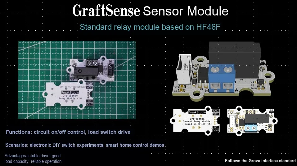
Ordinary relay module based on HF46F Ordinary relay module based on HF46F-G , the core is composed of HF46F-G ultra-small medium power relay, PC817 optocoupler, transistor drive circuit, etc.
- Among them,
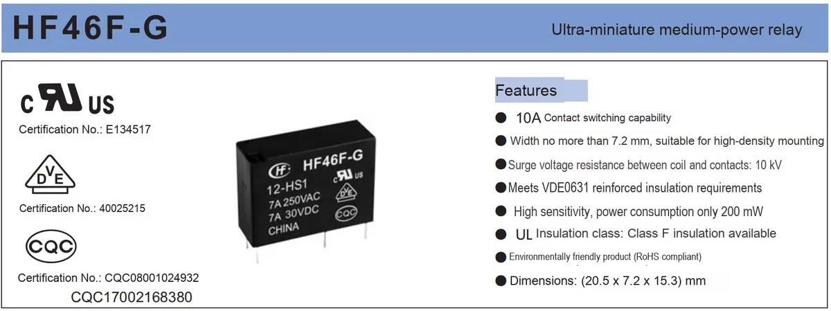
the HF46F-Grelay features a 10A contact switching capacity, an ultra-compact size (width ≤ 7.2mm), and an insulation voltage of 10kV between the coil and contacts, making it suitable for high-density installation scenarios; - The module adopts a circuit structure of optocoupler isolation + triode driving. After the control signal is input from the
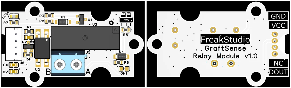
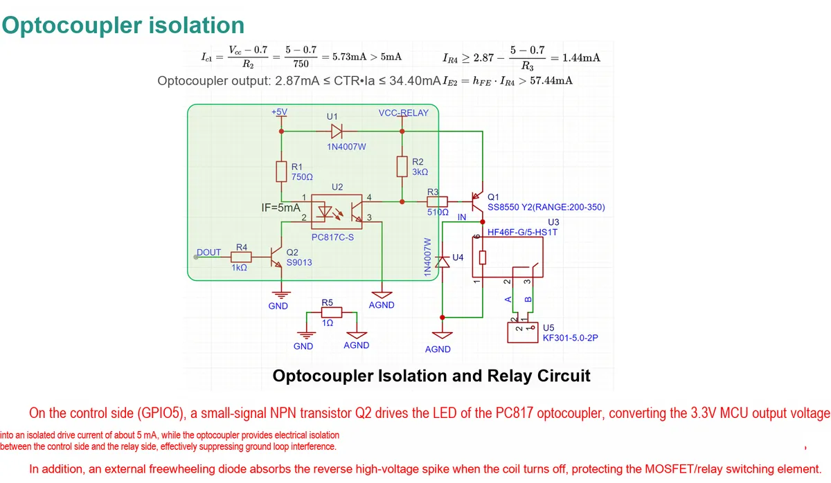
DOUTinterface, it realizes electrical isolation between the control terminal and the relay terminal viaPC817, then drives the triode to control the on/off of theHF46Frelay. Meanwhile, the circuit is equipped with a freewheeling diode to absorb the reverse voltage spike of the relay coil, and is also provided with a filter circuit and status indicator lights to ensure stability and visualization.
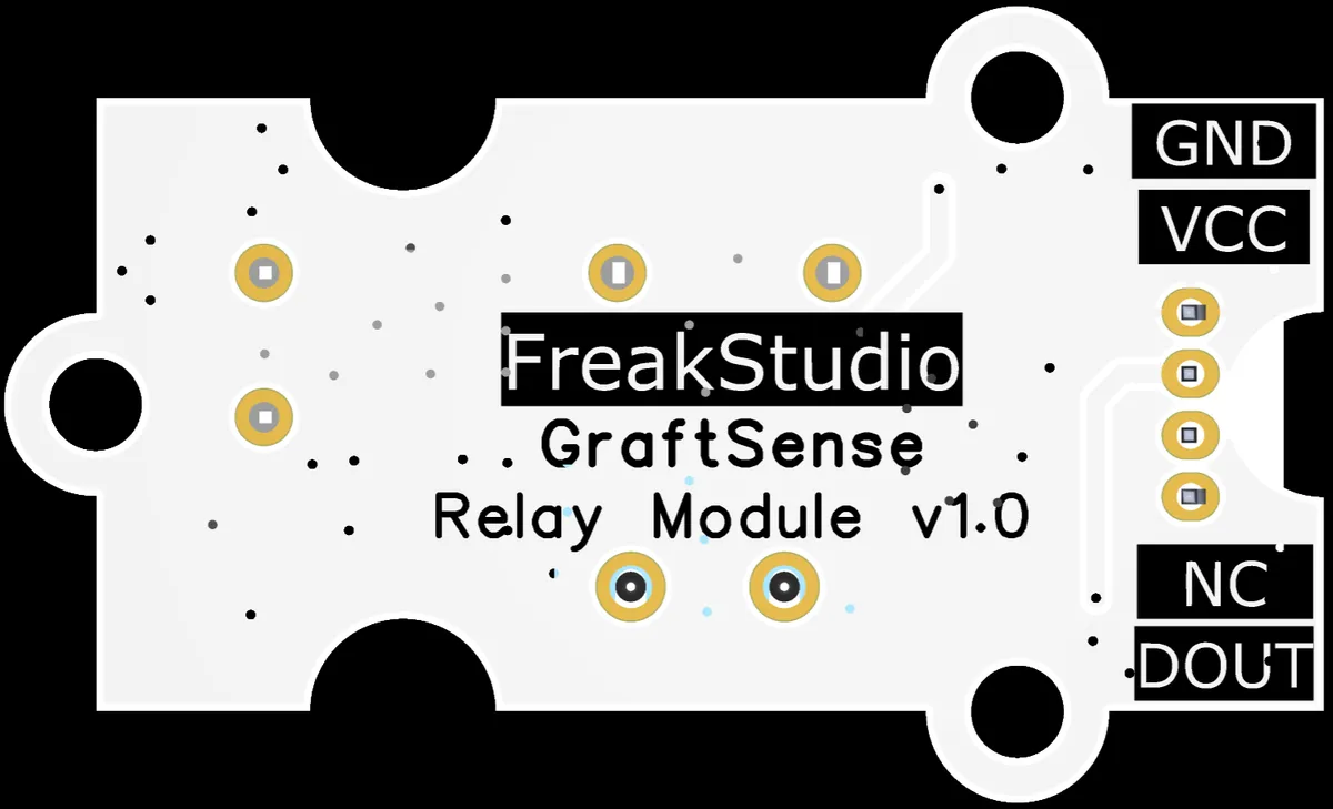
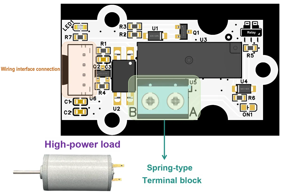
On the right side of the module, there are GND / VCC power supply interfaces, a NC (normally closed) pin and a DOUT control interface. The A / B terminals at the bottom can be connected to an external load, enabling convenient on-off control of high-power circuits via digital signals, which is both safe and practical.
II. Introduction to Main Chips
2.1 Chip Overview
2.1.1 HF46F-G Ultra-compact Medium-power Relay
2.1.2 PC817 Optocoupler Isolation Chip
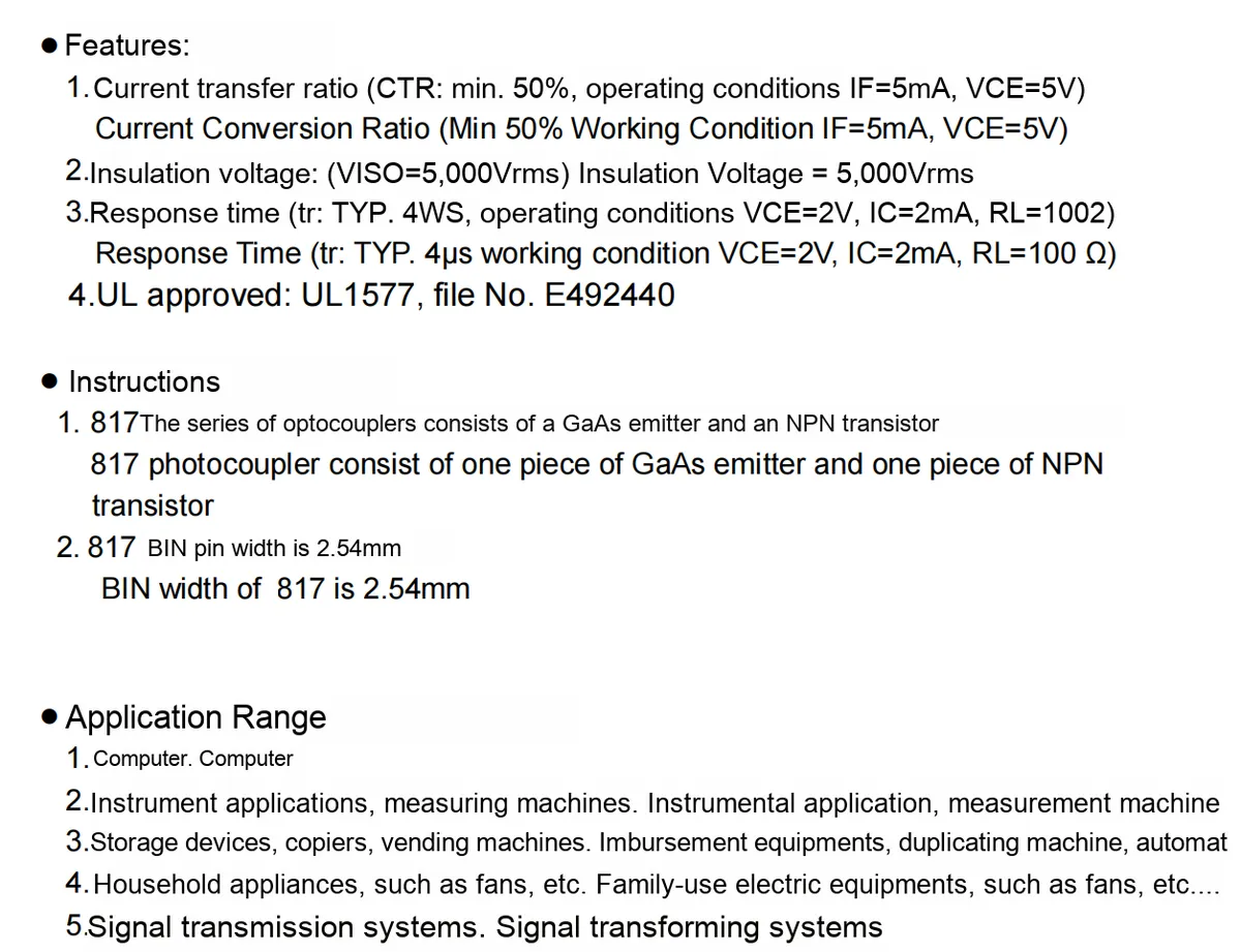
PC817 is a commonly used optocoupler, whose core consists of a GaAs light-emitting diode and an NPN phototransistor. It realizes electrical isolation between circuits through the "electricity-light-electricity" signal conversion (this is the core function of an optocoupler, which can isolate high and low voltages and suppress circuit interference).
2.2 Pin Definition
2.2.1 HF46F-G Ultra-compact Medium-power Relay
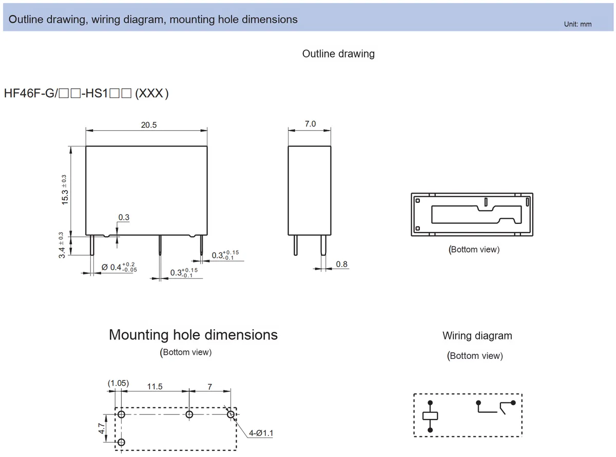
From the wiring diagram of the bottom view of the HF46F-G relay, it can be seen that its pins are divided into two categories: coil pins and contact pins:
- Coil pins: There are 2 in total, corresponding to the pin group on the left side of the wiring diagram, which are connected to the driving voltage to control the pull-in/release operation of the relay;
- Contact pins: There are 3 in total, corresponding to the single-pole double-throw (
SPDT) contact group on the right side of the wiring diagram, including the normally closed terminal (NC), common terminal (COM), and normally open terminal (NO) — when the relay is released, the common terminal conducts with the normally closed terminal; when the relay is energized, the common terminal conducts with the normally open terminal, which is used for connecting an external load circuit.
2.2.2 PC817 Optocoupler Isolation Chip
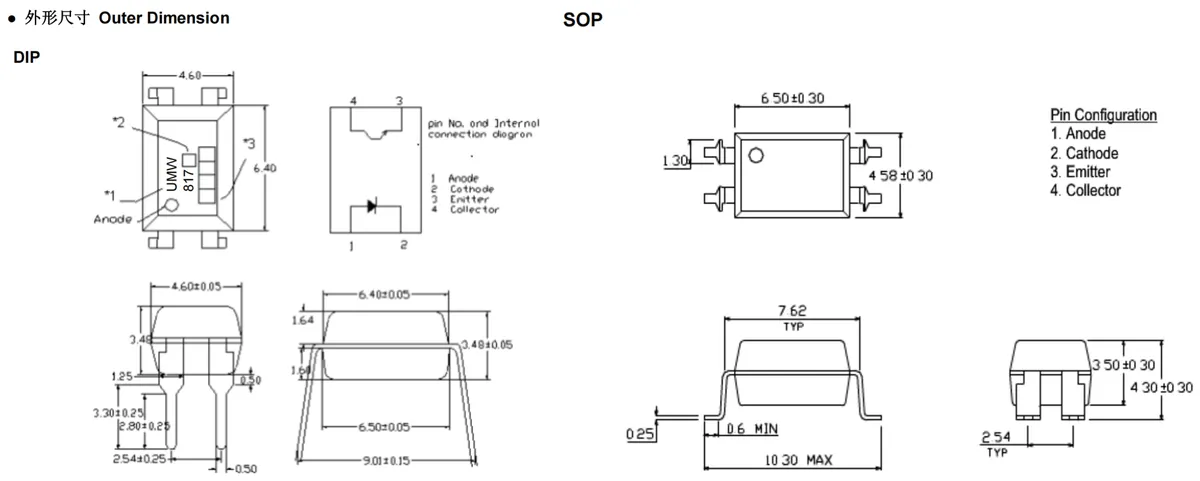
PC817 the pinout definition of the optocoupler is consistent across DIP and SOP packages, with a total of 4 pins, whose functions are as follows:
- Pin 1 (
Anode): The anode of the LED, connected to the high potential of the control terminal; - Pin 2 (
Cathode): The cathode of the LED, connected to the low potential of the control terminal; - Pin 3 (
Emitter): the emitter of the phototransistor, serving as the low-potential output terminal of the receiving end; - Pin 4 (
Collector): The collector of the phototransistor, serving as the high-potential output terminal of the receiving end.
In use, pins 1 and 2 are connected to a control signal (to drive the light-emitting diode to emit light), and pins 3 and 4 are connected to the load circuit (to receive the optical signal and convert it into an electrical signal for output), thereby achieving electrical isolation between the control end and the load end.
2.3 Functional Block Diagram
2.3.1 HF46F-G Ultra-compact Medium-power Relay
None.
2.3.2 PC817 Optocoupler Isolation Chip
None.
2.4 Performance Parameters
2.4.1 HF46F-G Ultra-compact Medium-power Relay
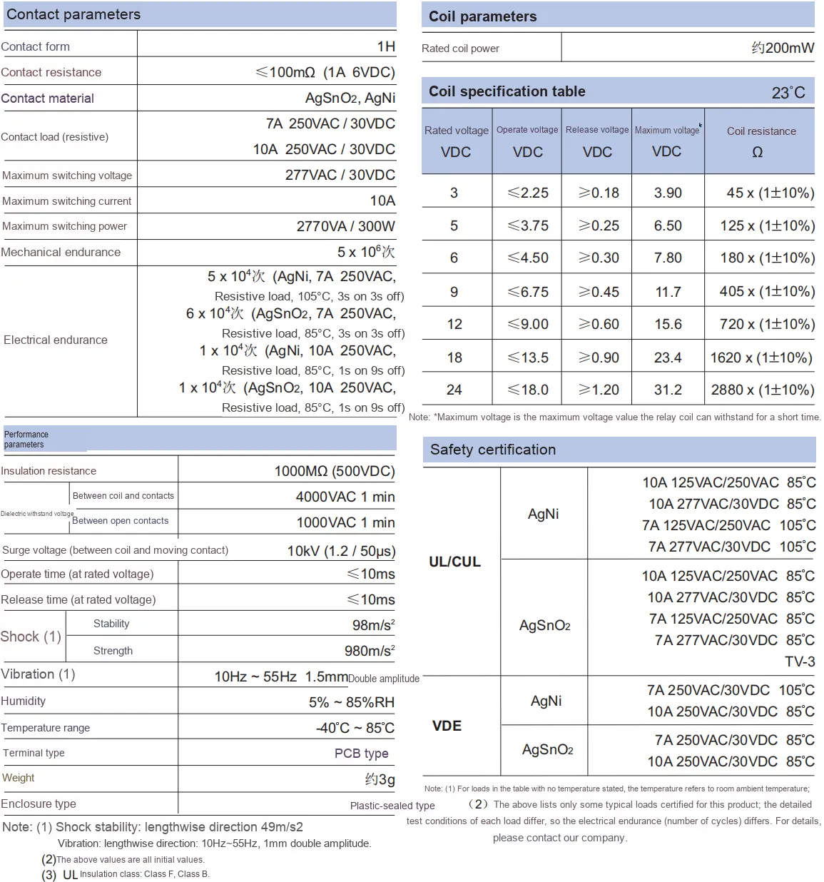
HF46F-G The key performance parameters of the relay can be understood from three aspects: contacts, coil, and insulation/mechanical properties:
- Contact Parameters: The contact form is
1H(single contact group), the contact resistance is ≤100mΩ(reflecting the conductivity when the contact is on, the smaller the resistance, the lower the loss), and the contact materials areAgSnO₂andAgNi(featuring both low resistance and wear resistance);Its resistive load capacity covers specifications including 7A/250VAC and 10A/250VAC, which refers to the resistive current it can stably carry at different voltages; it features a mechanical durability of up to 5×10⁸ cycles, representing its no-load switching lifespan, while its electrical durability varies with load type and ambient temperature — for instance, it delivers a lifespan of 1×10⁴ cycles under a 10A/250VAC resistive load, demonstrating its reliable performance in on-off operations with connected loads. - Coil Parameters: Rated power is approximately 200mW (the power for normal coil operation), with rated voltage covering 3~24VDC; operating voltage ≤ 75% of the rated value (e. g., ≤2.25V for a 3V coil, which is the minimum voltage required for relay pull-in), release voltage ≥ 6% of the rated value (e. g., ≥0.18V for a 3V coil, which is the critical voltage for relay release), and maximum voltage refers to the peak voltage that the coil can withstand instantaneously; coil resistance is the resistance value at 23°C corresponding to the rated voltage (reflecting the electrical characteristics of the coil).
- Insulation / Mechanical Properties: Insulation resistance of 1000MΩ(500VDC) and dielectric withstand voltage of 4000VAC (between coil and contacts) ensure insulation safety between circuits; surge voltage of 10kV enhances the capability to resist instantaneous high voltage; operate / release time ≤10ms (the response speed of relay pull-in and disengagement), along with mechanical strength to resist impact and vibration, adapting to an operating environment of -40~85℃.
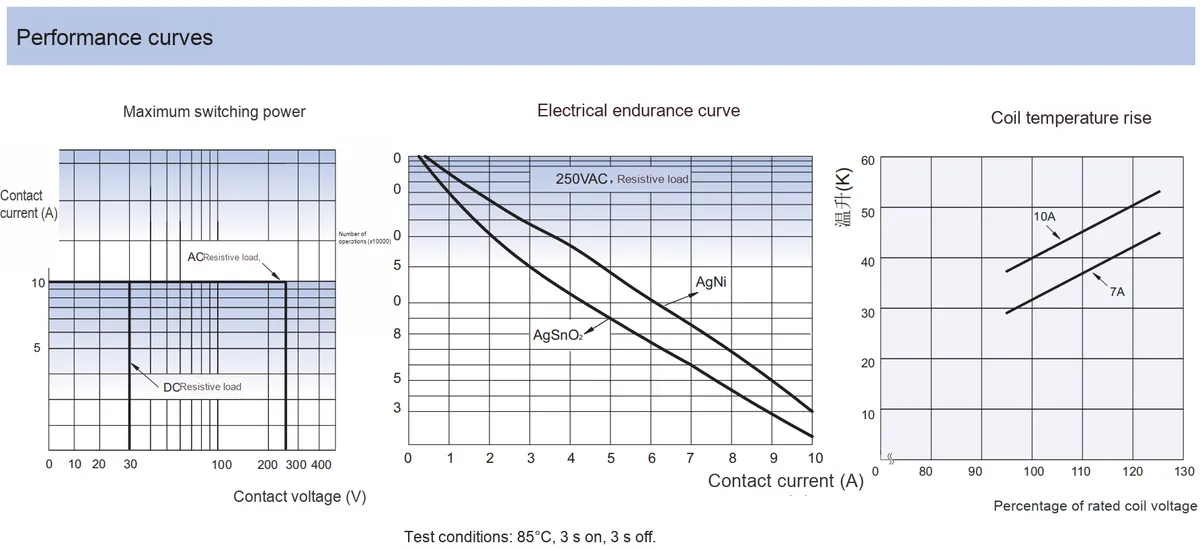
These three performance curves respectively reflect HF46F-G the operating characteristics of the relay in different dimensions:
- Maximum Switching Power Curve: With contact voltage on the horizontal axis and contact current on the vertical axis, it illustrates that
AC/DCunder resistive load, the maximum current that can be carried corresponding to different contact voltages (Power = Voltage × Current) — For example, for AC resistive load in the voltage range of 10~300V, the maximum contact current stabilizes at around 10A,DCthe corresponding carry current for resistive load is lower, which reflects the power bearing limit of relays under different voltages and load types. - Electrical durability curve: With contact current as the horizontal axis and number of operations (×10,000 times) as the vertical axis (test conditions: 85℃, 3s on, 3s off), it exhibits the rule that "the higher the contact current, the fewer the number of operations"(for example, the number of operations exceeds 100,000 times at 1A current, but only about 20,000 times at 10A); meanwhile, the electrical durability of AgNi contacts is slightly better than that of AgSnO₂, which reflects the influence of load current and contact material on the on-off life of relays under load.
- Coil temperature rise curve : the horizontal axis is the percentage of rated voltage of the coil (over rated voltage is the percentage > 100), the vertical axis is the temperature rise (
K), it can be seen that the actual voltage of the coil is higher than the rated value, the higher the temperature rise; and the temperature rise of the 10A working condition is higher than 7A, indicating that the coil overvoltage, the greater the load, the more serious the heating , which will directly affect the working stability and life of the relay.
2.4.2 PC817 Optocoupler Isolation Chip
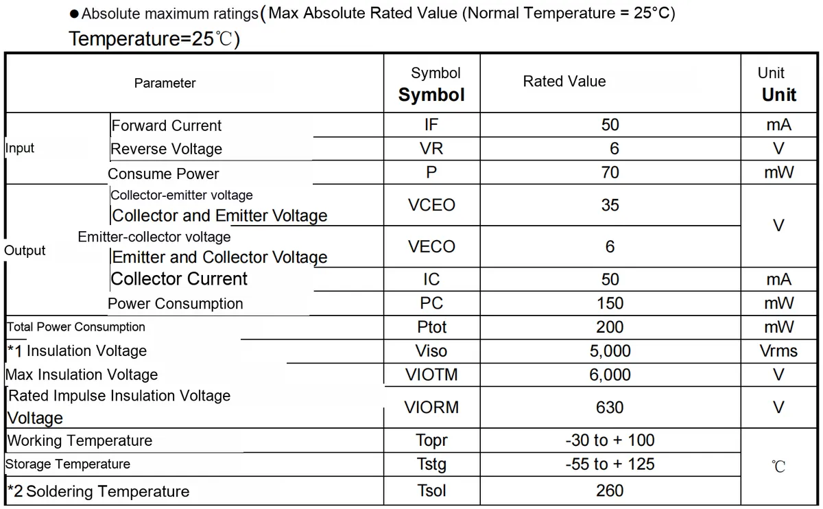
This table presents PC817 the maximum absolute ratings of the optocoupler at room temperature (25℃), and each parameter should be understood in combination with its structure of "light-emitting diode (input) + phototransistor (output)":
- Input terminal (light-emitting diode) parameters: Forward current
IF(50mA) is the maximum forward current that the light-emitting diode can withstand, and exceeding this value will burn out the diode; reverse voltageVR(6V) is the maximum reverse voltage that the light-emitting diode can tolerate; power dissipationP(70mW) is the upper limit of the maximum power dissipation of the light-emitting diode. - Output (Phototransistor) Parameters: Collector-Emitter Voltage
VCEO (35V), Emitter-Collector VoltageVECO (6V)are the withstand voltage limits for different polarities across the transistor; Collector CurrentIC(50mA) is the maximum current that can be output from the transistor's collector; Power DissipationPC(150mW) is the maximum power dissipation of the transistor. - General and Insulation Parameters: Total power consumption
Ptot(200mW) is the upper power consumption limit of the entire optocoupler; the isolation voltageViso(5000Vrms) refers to the electrical isolation voltage between the input and output terminals (for safety assurance), and there are also restrictions on the transient maximum isolation voltage (6000V) and impulse isolation voltage (630V). - Temperature Parameters: Operating temperature
Topr(-30 to + 100°C) refers to the temperature range for normal operation of the optocoupler; storage temperatureTstg(-55 to + 125°C) refers to the temperature range for storage; soldering temperatureTsol(260°C) refers to the upper temperature limit during soldering (to avoid chip damage caused by high temperature).
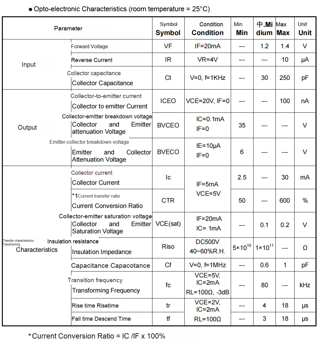
This table presents PC817 optocoupler's optoelectronic characteristics at room temperature (25°C), and the meaning of each parameter should be understood in combination with its "light-emitting diode - phototransistor" structure:
- Input Characteristics (Light-Emitting Diode Side): Forward Voltage
VF(IF= 20mA, typical value 1.2~1.4V) refers to the voltage drop when the light-emitting diode conducts in the forward direction, reflecting its conduction characteristics; Reverse CurrentIR(VR= 4V, maximum 10μA) is the leakage current of the light-emitting diode under reverse bias, and a smaller value indicates better reverse insulation performance; Collector CapacitanceCtis the parasitic capacitance of the phototransistor's collector, which affects the high-frequency signal transmission characteristics. - Output Characteristics (Phototransistor Side): Collector-Emitter Current
ICEO(VCE= 20V, maximum 100nA under no illumination) is the dark current of the phototransistor; a smaller value indicates a lower leakage current when there is no light. Collector-Emitter Breakdown VoltageBVCEO(minimum 35V) is the breakdown voltage between the collector and emitter of the phototransistor, ensuring the withstand voltage of the output terminal. Collector CurrentIc(2.5~30mA whenIF= 5mA) is the output current range of the phototransistor, reflecting its load-carrying capability. - Transmission Characteristics (Core Interaction Indicators): Current Transfer Ratio
CTR(IC/IF×100%, min. 50%, max. 600%) is a core parameter of optocouplers, which reflects the conversion efficiency from "light-emitting diode current to photosensitive transistor current", and its wide range adapts to different driving scenarios; Collector-Emitter Saturation VoltageVCE (sat)(typically 0.1V) is the voltage drop when the photosensitive transistor is in saturated conduction, and the smaller the value, the lower the conduction loss; Insulation ResistanceRiso(5×10¹⁰~1×10¹¹Ω) reflects the insulation isolation capability between the input and output terminals;Transition frequencyfc(typically 80kHz) is the upper bandwidth limit of the optocoupler, which determines the transmittable signal frequency; the rise/fall time (typically 4/3μs) reflects the signal response speed, and a smaller value indicates better dynamic characteristics.
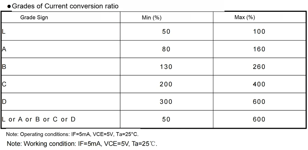
CTR refers to the conversion efficiency of an optocoupler from "input light-emitting diode current to output photosensitive transistor current (CTR = IC/IF × 100%), and different grades correspond to different conversion efficiency ranges:
CTRwith a lower grade (e. g.,L) is suitable for scenarios requiring "low output current and avoidance of over-driving";CTRat a higher level (e. g.,D) is suitable for scenarios where "a small input current drives a large output load".
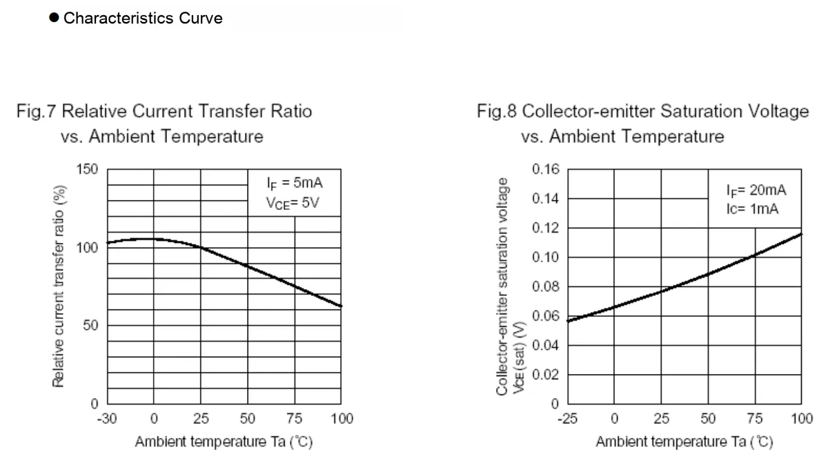
These two characteristic curves reflect the influence of ambient temperature on PC817 the core parameters of the optocoupler:
- Figure 7 (Relative Current Transfer Ratio vs. Ambient Temperature): Operating conditions are
IF= 5 mA,VCE= 5 V. The curve shows that in the range from low temperature (-30°C) to room temperature (25°C), the relative current transfer ratio (CTR) remains basically stable at around 100%; when the temperature exceeds 25°C, the relativeCTRgradually decreases as the temperature rises (drops to approximately 60% at 100°C).This is because the carrier characteristics of the phototransistor are affected by temperature, and an increase in temperature will reduce the conversion efficiency of "light-emitting diode current → phototransistor current", which means that the signal transmission capability of the optocoupler will be weakened in a high-temperature environment. - Figure 8 (Collector-Emitter Saturation Voltage vs. Ambient Temperature): Operating conditions are
IF= 20 mA,IC= 1 mA. The curve shows that the collector-emitter saturation voltage (VCE (sat)) gradually increases as the ambient temperature rises (from approximately 0.06 V at -25°C to about 0.12 V at 100°C).VCE (sat)refers to the voltage drop across the photosensitive triode when it is in saturated conduction; the higher this value, the greater the power loss during conduction. Therefore, high temperature will increase the conduction loss at the output side of the optocoupler, affecting the energy efficiency performance of the circuit.
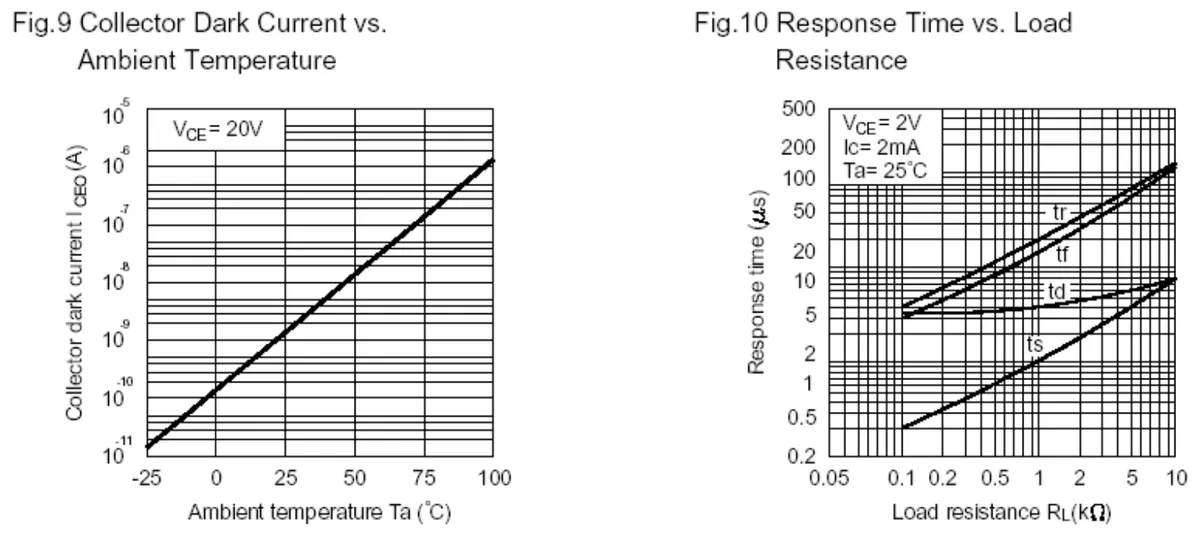
These two characteristic curves respectively reflect the influences of ambient temperature and load resistance on PC817 optocoupler's key parameters:
- Figure 9 (Collector Dark Current vs. Ambient Temperature): The collector dark current (
ICEO) refers to the leakage current between the collector and emitter of the phototransistor when the optocoupler is in a no-light condition (IF= 0), with the test condition beingVCE= 20V. The curve (with the vertical axis in logarithmic scale) shows that when the ambient temperature rises from -25°C to 100°C,ICEOincreases sharply (from approximately 10⁻¹¹ A to 10⁻⁵ A).This is because an increase in temperature will raise the number of hot carriers in the semiconductor, leading to a rise in the reverse leakage current of the phototransistor, which means that the "no-signal interference" capability of the optocoupler will degrade significantly in high-temperature environments. - Figure 10 (Response Time vs. Load Resistance): The response time (including rise time
tr, fall timetf, delay timetd, and storage timets) is a dynamic characteristic of the optocoupler (test conditions:VCE= 2 V,IC= 2 mA, room temperature 25℃). The curve shows that as the load resistanceRLincreases, all response times gradually lengthen (for example, whenRLrises from 0.05 kΩ to 10 kΩ,trincreases from several microseconds to nearly 200 μs).This is because the load resistor determines the charging and discharging rate of the phototransistor's collector. The larger the RL, the slower the current change. Therefore, when the optocoupler transmits high-speed signals, the value of the load resistor needs to be controlled to insufficient response speed.
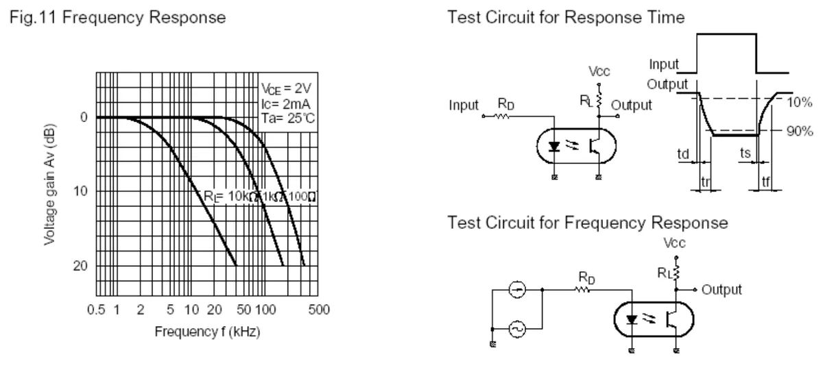
This set of diagrams illustrates PC817 the frequency response characteristics of the optocoupler and the corresponding test circuit, with analysis combined with the meaning of the parameters as follows:
- Fig. 11 Frequency Response Curve: The test conditions are as follows:
VCE= 2 V,IC= 2 mA, room temperature at 25°C; the horizontal axis represents the signal frequency (kHz), and the vertical axis denotes the voltage gainAv(dB). The curve demonstrates that: in the low-frequency band (<10 kHz), the voltage gain remains basically stable around 0 dB; when the frequency exceeds the critical value, the gain decreases as the frequency rises(reflecting the bandwidth limitation of the optocoupler);Meanwhile, the smaller the load resistanceRL(e. g., 100Ω), the higher the "cutoff frequency" at which the gain starts to drop — this is becauseRLis smaller, the smaller the charge-discharge time constant of the phototransistor's collector, the faster the signal response speed, thus it can adapt to higher-frequency signal transmission. - Test circuit on the right side:
- Response time test circuit: the input is connected to a current-limiting resistor
Rd, the output is connected to a loadRL, and by inputting a square wave signal in combination with the Sequence Diagram, the delay timetd, rise timetr, storage timets, and fall timetf(all based on the 10%/90% level criteria) are defined, which is used to measure the dynamic response speed of the optocoupler; - Frequency response test circuit: with the input connected to an AC signal source and
Rd, and the output connected toRL; by measuring the output voltage gain at different frequencies, a frequency response curve is plotted to verify the high-frequency transmission capability of the optocoupler.
- Response time test circuit: the input is connected to a current-limiting resistor
Together with the circuit, these curves clearly demonstrate that the high-frequency transmission capability of the PC817 is affected by the load resistor: a smaller load resistor can increase its bandwidth, and the test circuit serves as the standard configuration for verifying these dynamic characteristics.
2.5 Reference Circuit
2.5.1 HF46F-G Ultra-compact Medium-power Relay
None.
2.5.2 PC817 Optocoupler Isolation Chip
None.
2.6 Chip Configuration
2.6.1 HF46F-G Ultra-compact Medium-power Relay
None.
2.6.2 PC817 Optocoupler Isolation Chip
None.
2.7 Communication Interfaces and Related Protocols
2.7.1 HF46F-G Ultra-compact Medium-power Relay
None.
2.7.2 PC817 Optocoupler Isolation Chip
None.
2.8 PCB Routing Notes
2.8.1 HF46F-G Ultra-compact Medium-power Relay
None.
2.8.2 PC817 Optocoupler Isolation Chip
None.
3. Instructions for Circuit Engineering and Module Usage
3.1 Circuit Source Engineering
To obtain the circuit source project, please follow the official account [Freak Embedded]
3.2 Module Usage Instructions
The schematic diagram is shown as follows:
SCH_General Relay Module Based on HF46F_v1.0_2025-11-26.pdf 2.3 MB
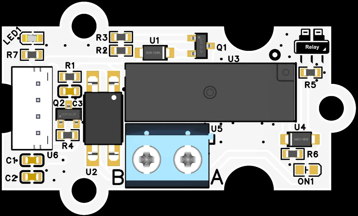
This module provides the DOUT interface:
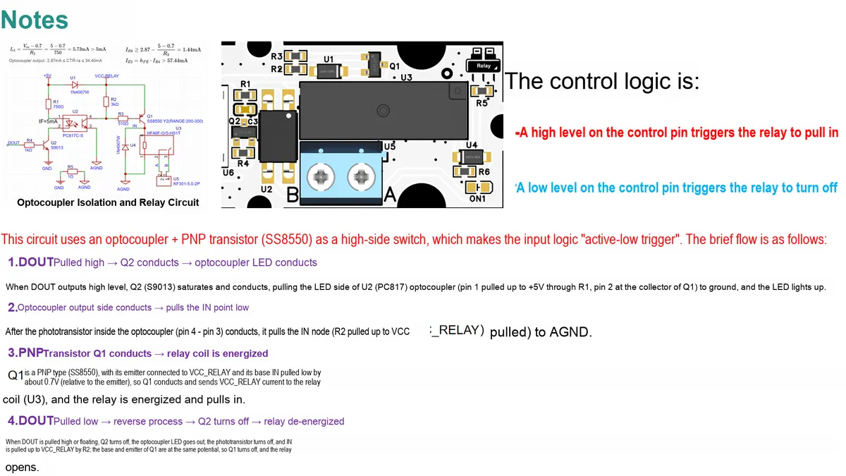
- When
GPIOoutputs a high level toDOUT, it can trigger the conduction ofQ2(S9013) in the circuit, turn on the optocoupler, and finally close the relay; - When GPIO outputs a low level to
DOUT, it will cut offQ2, turn off the optocoupler, and finally cause the relay to release.
When in use, we can just connect them in the following form:
The detailed analysis and explanation of the circuit principle are as follows:
At the same time, we also tested the relevant power:
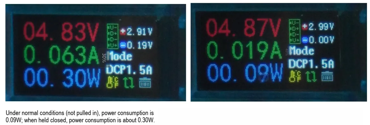
3.3 Application Experiment
Here, we use the GraftPort-RP2040 development board for testing, and connect the common relay module based on HF46F to communicate with the main controller via the DIO interface.
Here, we first use the HY2.0-4P connection cable to connect the module to the GraftPort-RP2040 development board's DIO1 interface:
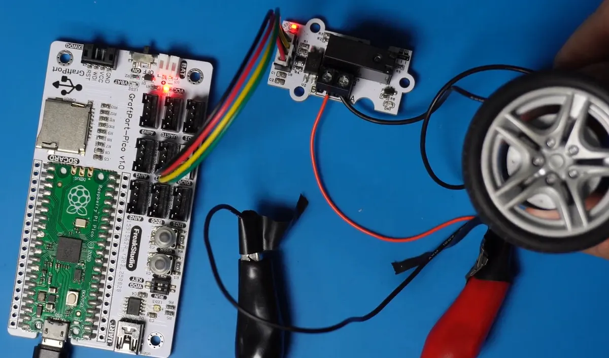
The module connections are shown in the following table:
Development Board Pins | Module Pins | Description |
Pin 14 |
| The pins connected to the MCU output high and low levels. |
Pin 15 |
| - |
- Power supply output
5Vvoltage, which is divided into two lines: positive pole andGND(negative pole). - The positive terminal of the power supply is connected to node
A, serving as the positive input terminal of the power supply backbone. - The positive terminal of the motor (Motor +) is not directly connected to the power supply, but is connected to the output terminal of the relay.
- Power supply
GNDis directly connected to the negative terminal of the motor (motor -) to form the foundation of the circuit.
Here, we need to search for the relevant driver packages on uPyPI: https://upypi.net/zh/

Enter relay_driver to search, and the following will be displayed:

Click to copy the local installation command:
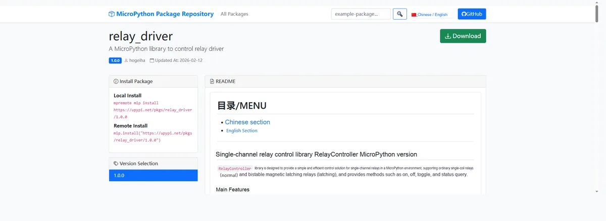
Here, we can use the mip tool to import module driver library code. Below are the usage commands for the mpremote tool:
mpremote mip install github:FreakStudioCN/GraftSense-Drivers-MicroPython/misc/relay_driverAfter importing the relay module driver - MicroPython driver code, copy the following main.py code into our project:
# Python env   : MicroPython v1.23.0
# -*- coding: utf-8 -*-
# @Time    : 2024/7/28 3:00 PM
# @Author  : Li Qingshui
# @File    : main.py
# @Description : Relay test example

# ======================================== Import Modules ========================================

# Import time-related modules
import time
# Import the relay module
from relay import RelayController

# ======================================== Global Variables ============================================

# If it is a 'normal' type relay, use GP14
RELAY_TYPE = 'normal'   # 'normal' or 'latching'
RELAY_PIN1 = 14           # Control pin 1
RELAY_PIN2 = 15           # Control pin 2

# Music rhythm definition (unit: ms)
# Each tuple represents (duration, whether to toggle at the end)
MUSIC_NOTES = [
    # Strong rhythm in the intro
    (50, True), (50, False), (50, True), (50, False),  # 4 fast consecutive beats
    (100, True), (100, False),  # Slow down for 2 beats
    (50, True), (50, False), (50, True), (50, False),  # Repeat 4 fast beats

    # Verse section
    (150, True), (50, True), (200, False),  # Strong-light-long pause
    (100, True), (100, True), (100, True), (100, False),  # Three consecutive hits
    (80, True), (80, True), (160, False),  # Double beat + long pause
    (60, True), (60, True), (60, True), (60, True), (120, False),  # Four fast consecutive hits

    # Chorus climax
    (40, True), (40, False), (40, True), (40, False),  # Ultra-fast eighth notes
    (40, True), (40, False), (40, True), (40, False),
    (200, True), (200, False),  # Strong downbeat
    (300, True), (100, True), (200, False),  # Long-short combination

    # Bridge tempo change
    (120, True), (80, True), (120, True), (80, False),
    (200, True), (50, True), (50, True), (200, False),

    # Ending slows down gradually
    (150, True), (150, False),
    (200, True), (200, False),
    (300, True), (300, False)
]
# ======================================== Functions ============================================

# Simple music playback function
def play_relay_music():
    for duration, should_toggle in MUSIC_NOTES:
        # Toggle the relay state
        relay.toggle()
        time.sleep_ms(duration)
        if should_toggle:
            # Toggle back again
            relay.toggle()
            # Add a small interval to prevent toggling too fast
            time.sleep_ms(50)

# ======================================== Custom Classes ============================================

# ======================================== Initialization ==========================================

# Power-on delay of 3 s
time.sleep(3)
# Print debug information
print("FreakStudio: Using GraftPort to control relay")

# Initialize the relay controller
if RELAY_TYPE == 'latching':
    relay = RelayController(RELAY_TYPE, RELAY_PIN1, RELAY_PIN2)
else:
    relay = RelayController(RELAY_TYPE, RELAY_PIN1)

# ========================================  Main Program  ===========================================

# Turn on the relay
relay.on()
print('relay.on')
# Delay 1s
time.sleep(5)
# Turn off the relay
relay.off()
print('relay.off')
Burn the code, open a terminal, and use the mpremote tool to connect to the main controller; the output is as follows:

We can hear that the relays close and release in a certain regular pattern, just like music.
It can be observed that when the relay is closed, the motor starts to rotate; after 5 seconds, the relay opens and the motor stops.
IV. Drivers
relay_driver.zip 11 KB
5. BOM & Recommended Alternative Parts
None.
VI. Revision History
Document Version | Date of Revision | Modifier | Modify Content |
v1.0 | 2025-11-26 | Li Zisheng | Initialize the document The BOM sheet has not been finally checked, the driver has not been re-verified, and the 3.3 application experiment Not yet specified. |
v1.1 | 2025-12-29 | Li Zisheng | Added application experiments and production files |
v1.2 | 2025-12-31 | Xin Ruili | Create an open version of the document based on the internal document version v1.1. |
v1.3 | 2026-03-29 | Xin Ruili | Modified the application experiment section |
VII. Relevant Materials
7.1 Chip Datasheet
C3008369_Transistor Output Optocoupler_PC817C-S_Datasheet_WJ644212.PDF 461 KB
C5274026_Power Relay_HF46F-G-5-HS1T_Datasheet_WJ36712.PDF 126 KB
7.2 Unique Icons for PCB Silk Screen