Contents
- I. Module Introduction
- II. Introduction to Main Chips
- 2.1 Chip Overview
- 2.2 Pin Definition
- 2.3 Functional Block Diagram
- 2.4 Performance Parameters
- 2.5 Reference Circuit
- 2.6 Chip Configuration
- 2.7 Communication Interfaces and Related Protocols
- 2.8 PCB Routing Notes
- 3. Instructions for Circuit Engineering and Module Usage
- 3.1 Circuit Source Engineering
- 3.2 Module Usage Instructions
- 3.3 Application Experiment
- IV. Drivers
- 5. BOM & Recommended Alternative Parts
- VI. Revision History
- VII. Relevant Materials
- 7.1 Chip Datasheet
- 7.2 Unique Icons for PCB Silk Screen
I. Module Introduction
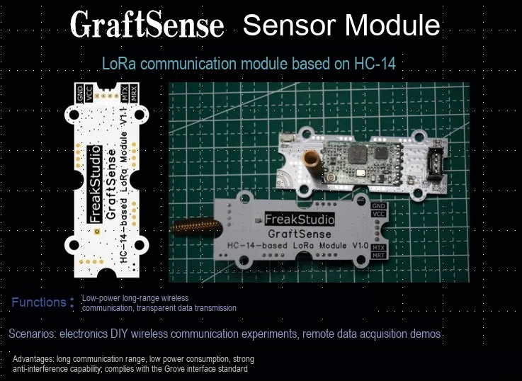
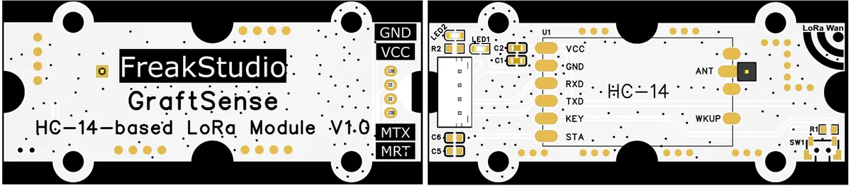
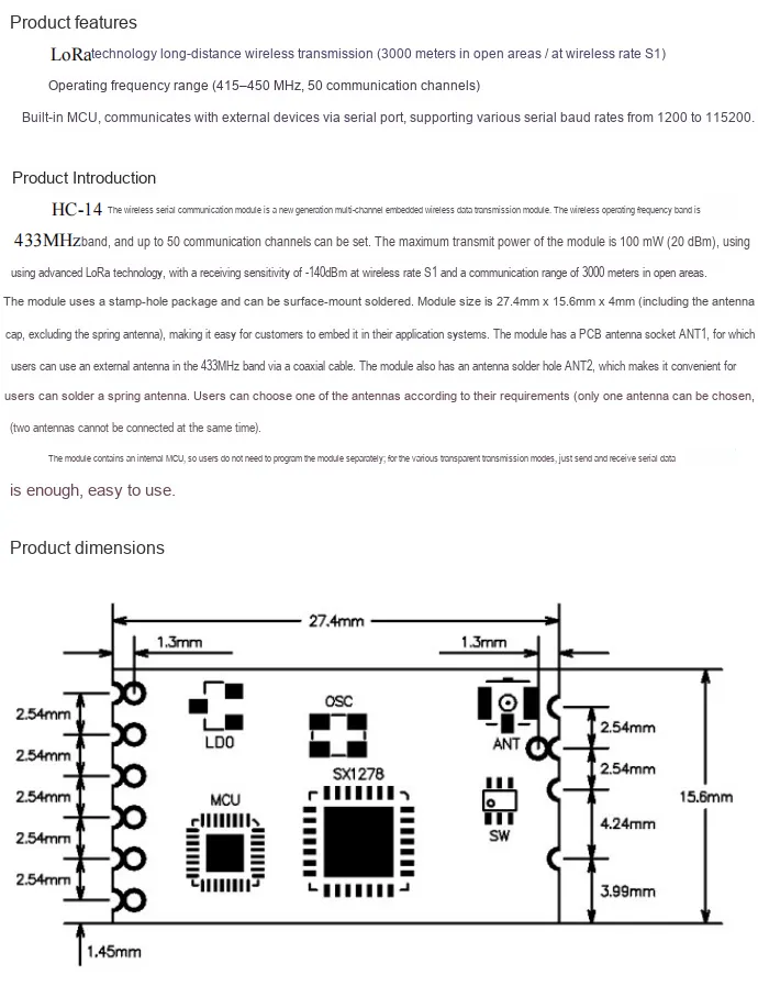
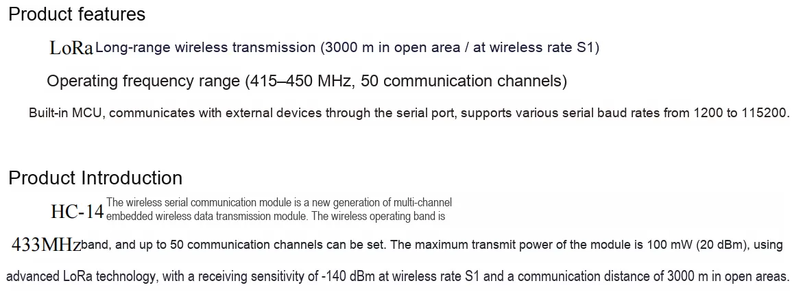
The LoRa communication module based on HC-14 is a HC-14 -based LoRa communication module that operates in the 433MHz band, supports 3.3V power supply, and communicates via TXD / RXD serial port. The KEY pin can enter the AT command mode, the STA pin indicates the working status, and it is equipped with a dual-antenna scheme of PCB antenna socket and welding holes. It is suitable for long-distance and low-power wireless communication scenarios, and provides a reliable LoRa wireless data transmission solution for IoT devices.
II. Introduction to Main Chips
2.1 Chip Overview
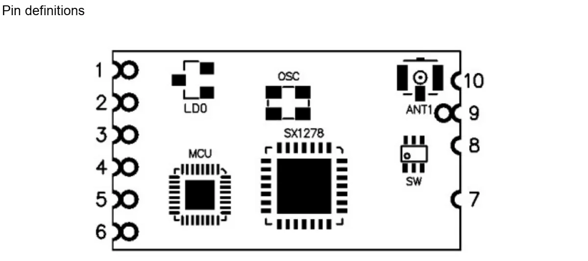
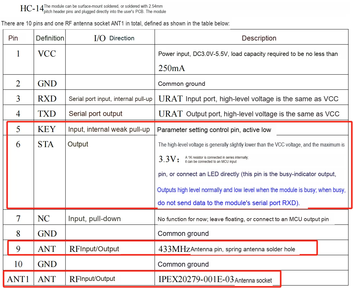
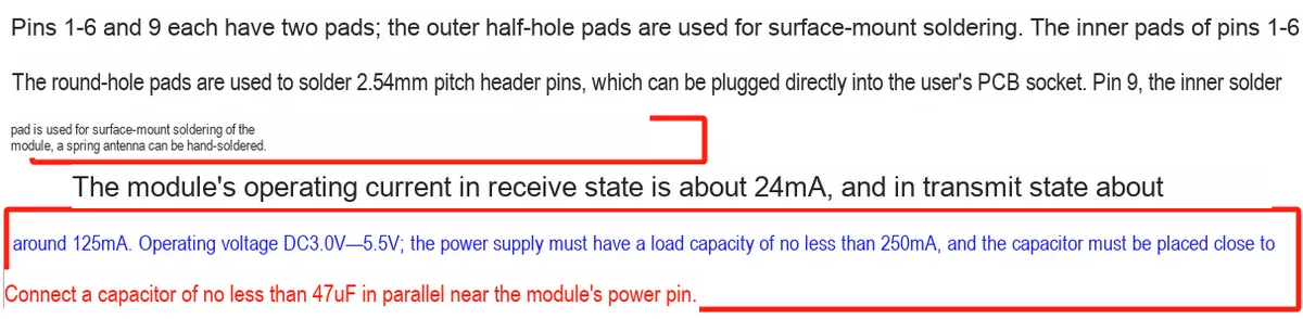
2.2 Pin Definition
2.3 Functional Block Diagram
None.
2.4 Performance Parameters
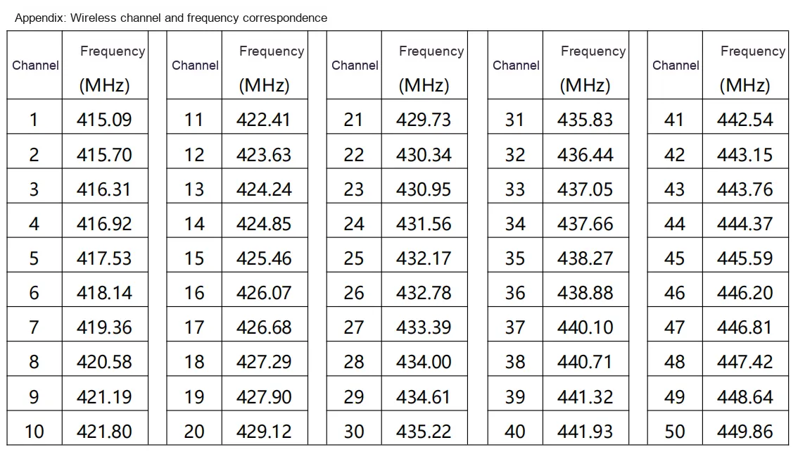
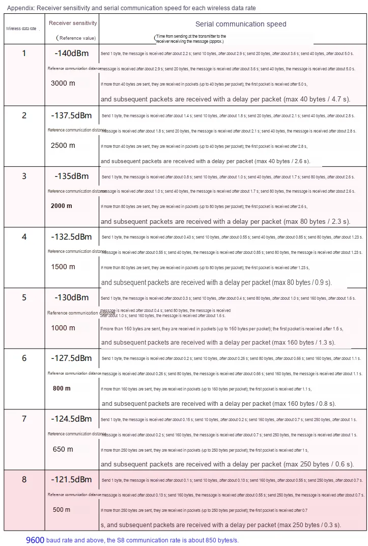
2.5 Reference Circuit
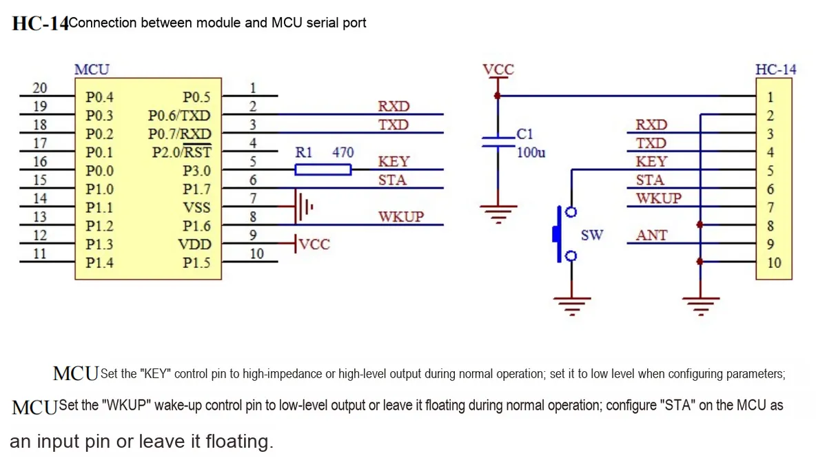
2.6 Chip Configuration
None.
2.7 Communication Interfaces and Related Protocols
2.7.1 Brief Introduction to Serial Port Transparent Transmission Principle
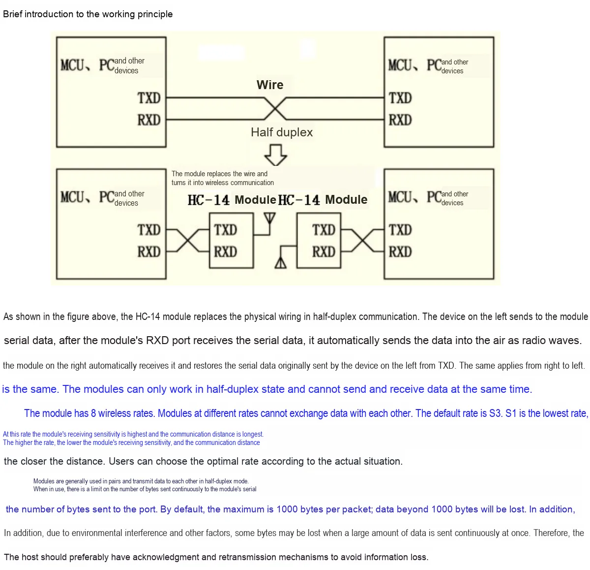
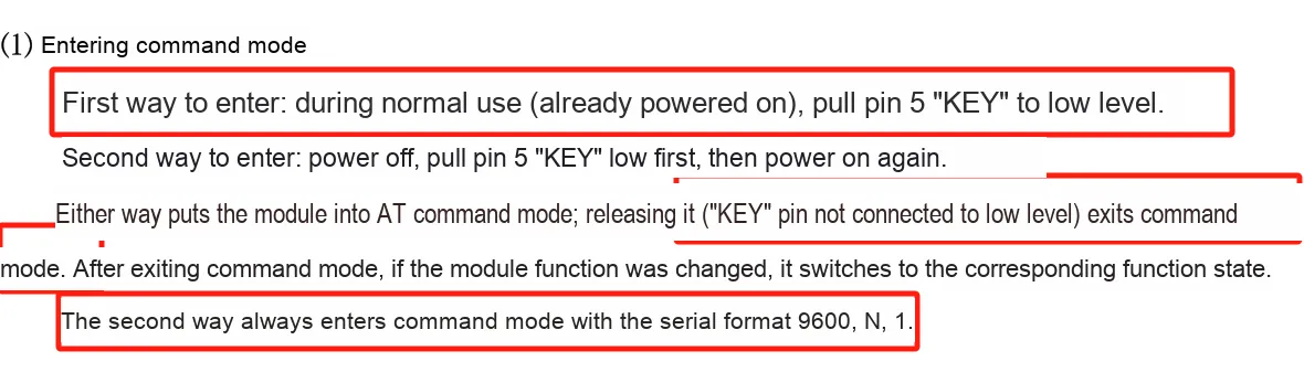
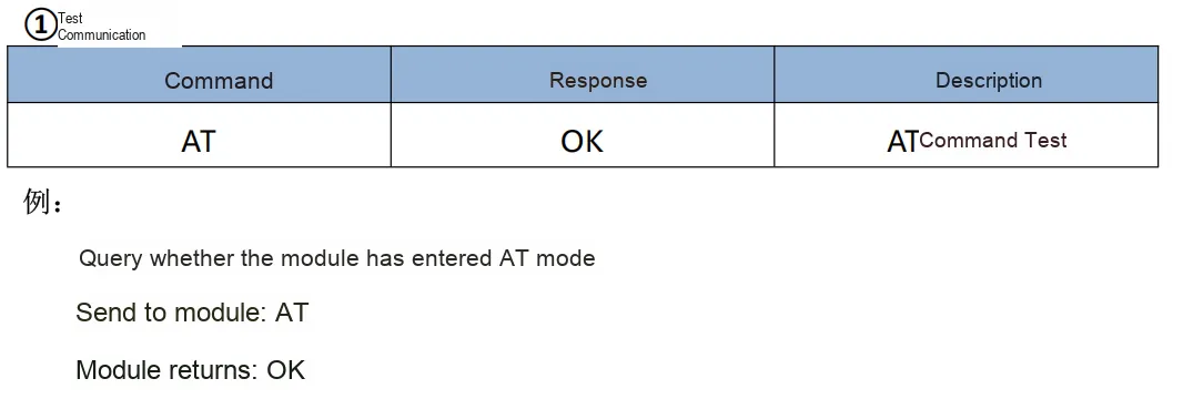
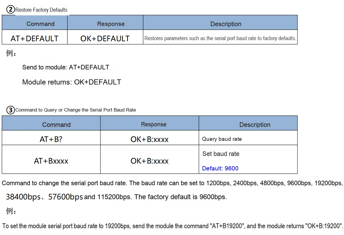
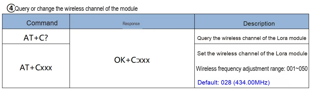
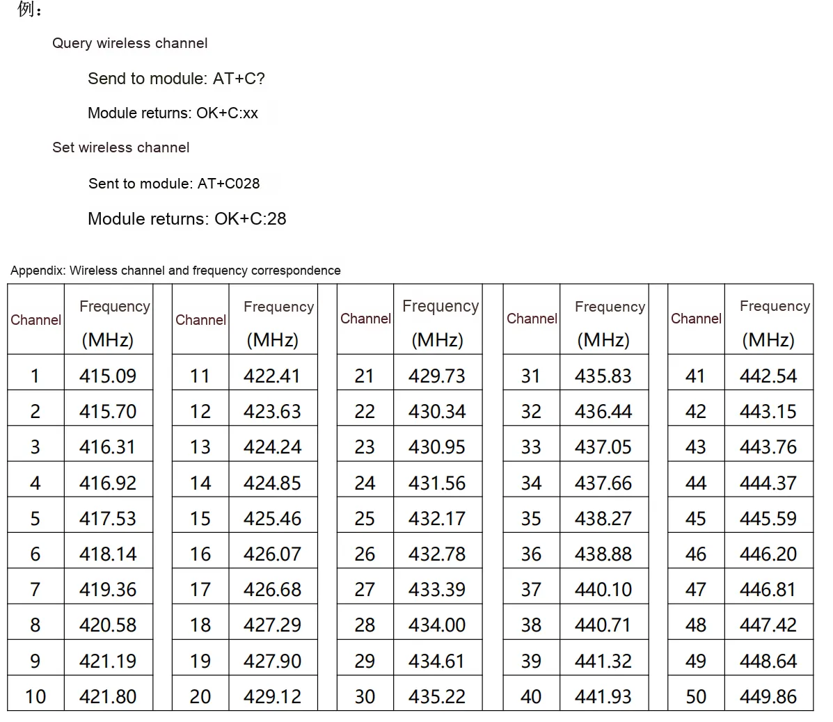
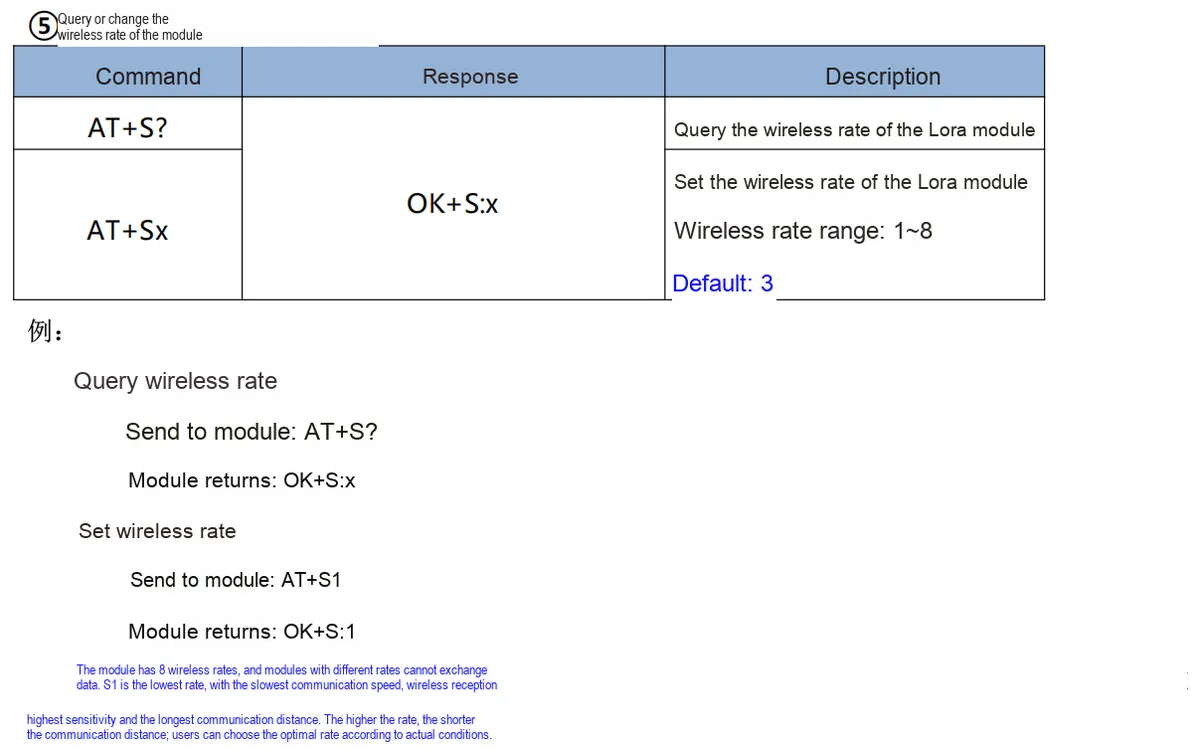
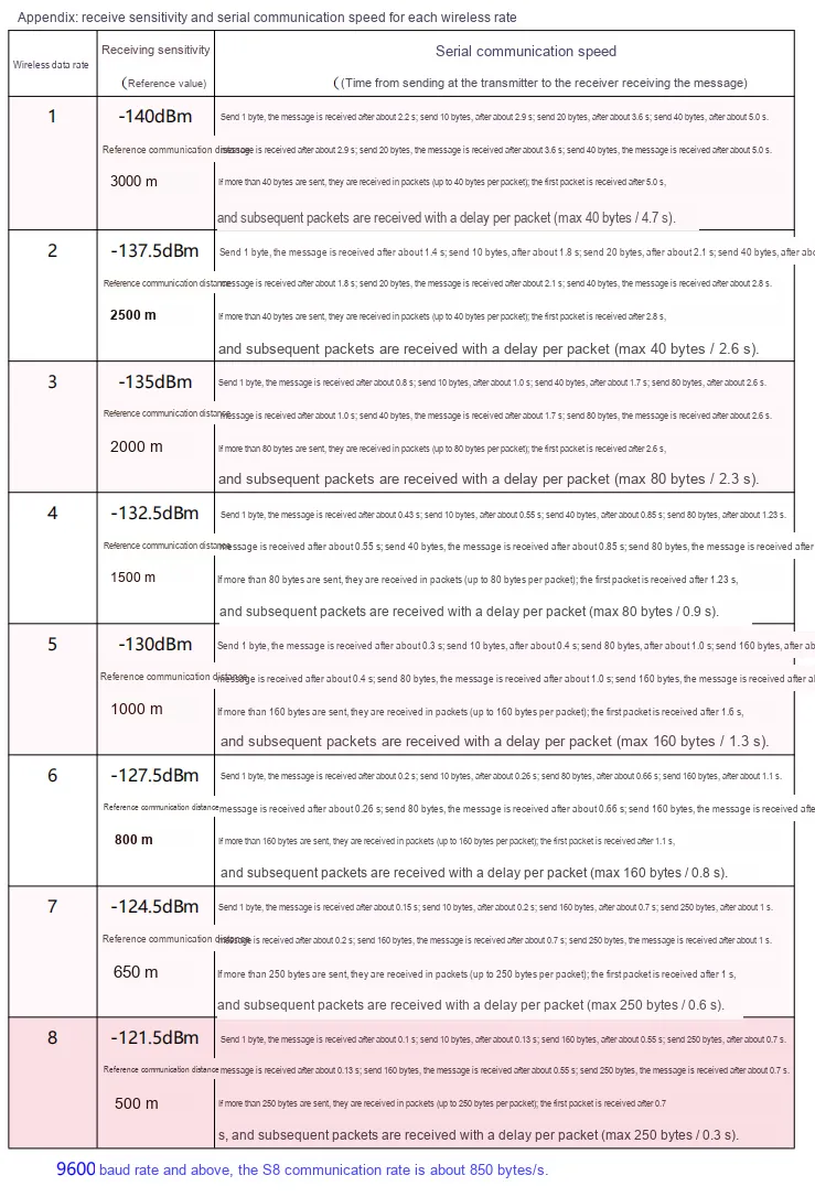
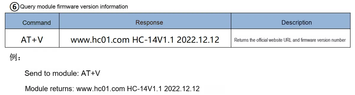
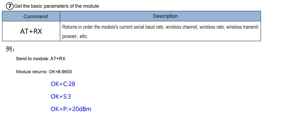
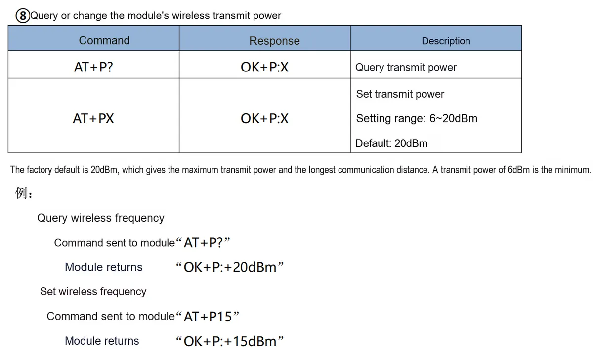
2.7.2 AT Command Related
2.8 PCB Routing Notes

3. Instructions for Circuit Engineering and Module Usage
3.1 Circuit Source Engineering
To obtain the circuit source project, please follow the official account [Freak Embedded]
3.2 Module Usage Instructions
The schematic diagram of this module is shown below:
SCH_LoRa Communication Module Based on HC-14_v1.0_2025-10-24.pdf 2.4 MB
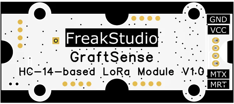
This module provides the serial port UART interfaces MRX and MTX: here M stands for master, meaning it is the MCU 's RX corresponding to the module' s TX.
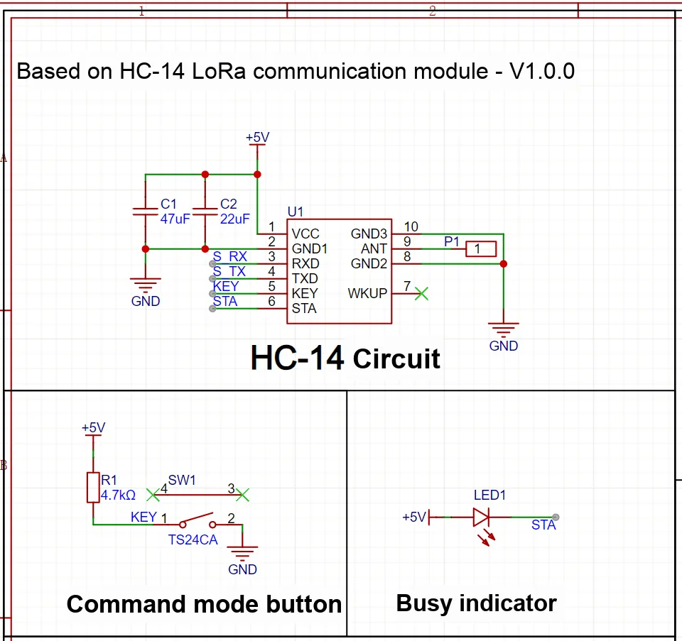
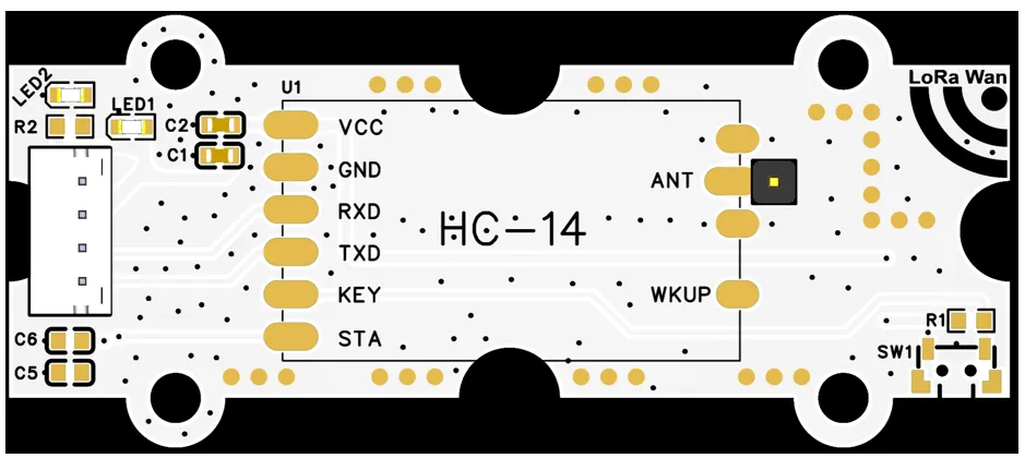
The meanings of some other buttons and indicator lights are as follows:
KEYpin is used forATcommand mode switching: it supports two entry methods: "pull low upon power-on" or "pull low before power-on", and exiting only requires releasing the KEY pin; the default serial port format is 9600, N, 1;The STApin serves as a busy status output: it stays at high level under normal conditions, outputs low level when the module is busy with communication, and can be connected to an externalLEDor directly connected to anMCUto check the working status;
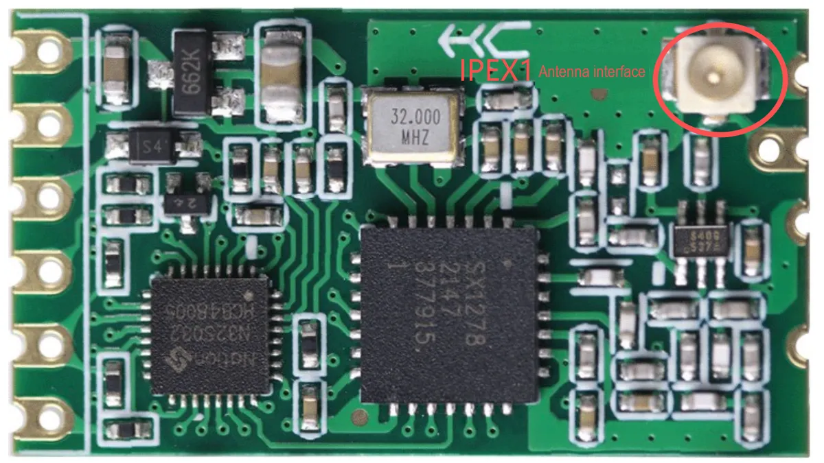
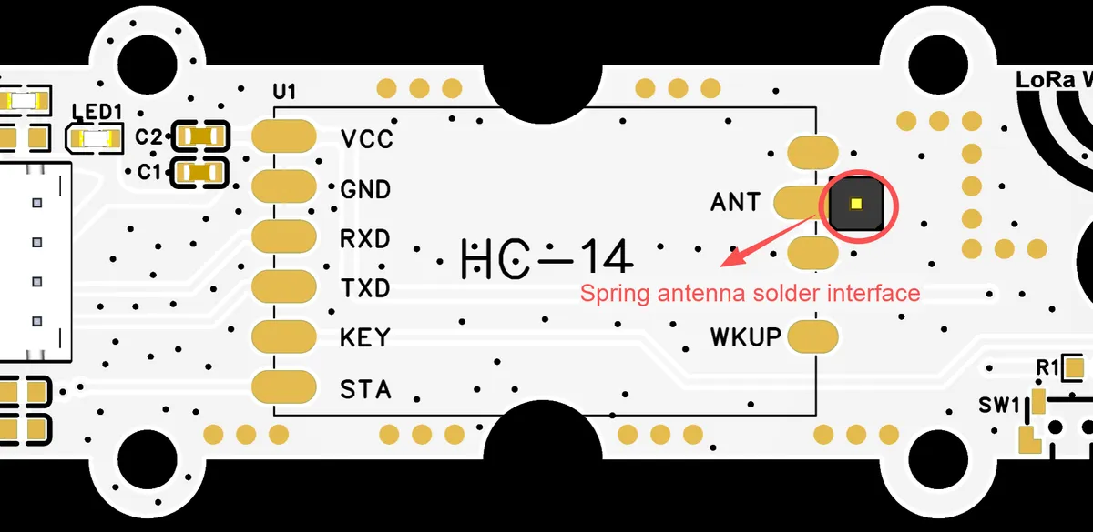
Regarding the antenna interface selection, the antenna interface offers dual options: ANT pin can be soldered with a spring antenna, ANT1 is an IPEX20279-001E-03 socket adapted for coaxial antenna (only one of the two is selectable);
3.3 Application Experiment
Here, we use the GraftPort-RP2040 development board for testing, and connect the HC-14-based LoRa communication module to communicate with the main controller via the UART interface.
Here, we first use the HY2.0-4P cable to connect the module to the GraftPort-RP2040 development board's UART0 interface:
The module connections are shown in the following table:
Development Board Pins | Module Pins | Description |
Pin 8 |
|
|
Pin 9 |
|
|
Development Board Pins | Module Pins | Description |
Pin 16 |
|
|
Pin 17 |
|
|
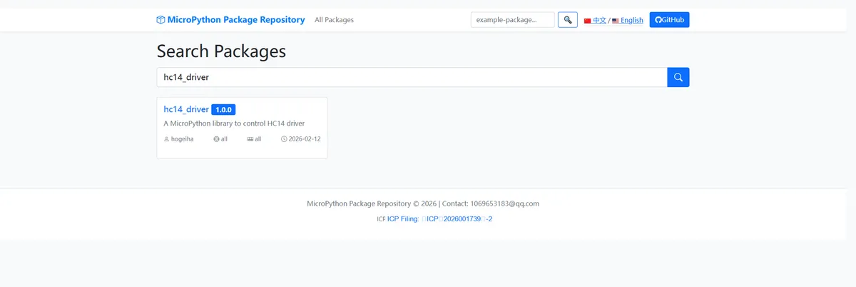
Here, we need to search for the relevant driver packages on uPyPI: https://upypi.net/zh/
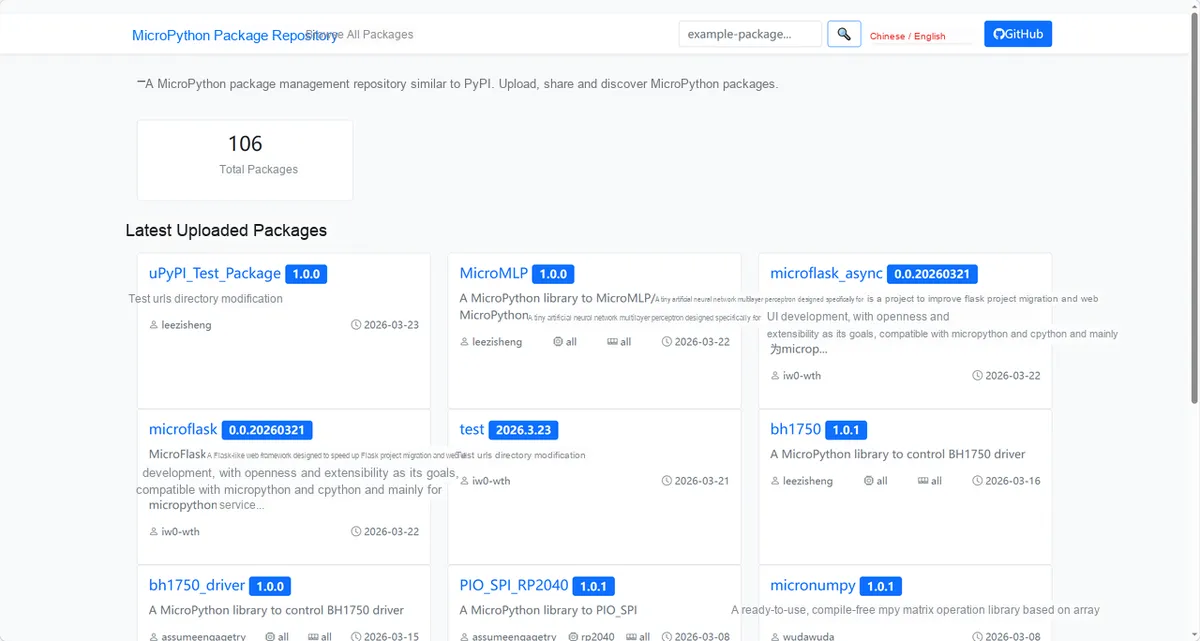
Enter hc14_driver to search, and the following will be displayed:
Click to copy the local installation command:
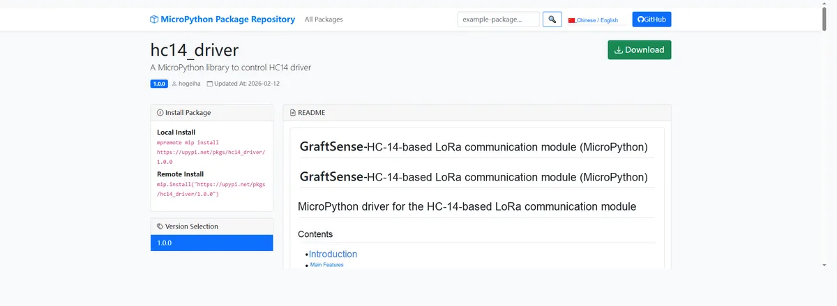
Here, we can use the mip tool to import module driver library code. Below are the usage commands for the mpremote tool:
mpremote mip install github:FreakStudioCN/GraftSense-Drivers-MicroPython/communication/hc14_driverImport the HC14 LoRa driver library - MicroPython driver code, then copy the following main.py code into our project:
# Python env   : MicroPython v1.23.0
# -*- coding: utf-8 -*-
# @Time    : 2025/9/5 10:11 PM
# @Author  : ben0i0d
# @File    : main.py
# @Description : hc14_lora test file

# ======================================== Import Modules =========================================

import time
from machine import UART, Pin, Timer
from hc14_lora import HC14_Lora
import urandom
from micropython import const

# ======================================== Global Variables ============================================

# LoRa parameter configuration
# Set the channel
channel = const(7)
# Set the random send data length
data = const(80)
# Set the transmit power
power = const(20)
# Set the transmission rate
rate = const(7)

# ======================================== Functions ============================================

# ======================================== Custom Classes =============================================

# ======================================== Initialization configuration ===========================================

# Power-on delay of 3 s to give the module time to stabilize
time.sleep(3)

print("FreakStudio: HC14_Lora Test Start")

# Initialize UART communication (adjust TX/RX according to the actual hardware wiring)
uart0 = UART(0, baudrate=9600, tx=Pin(16), rx=Pin(17))
uart1 = UART(1, baudrate=9600, tx=Pin(8), rx=Pin(9))

# Create an HC14_Lora instance
hc0 = HC14_Lora(uart0)
hc1 = HC14_Lora(uart1)

# ======================================== Main Program ===========================================

# Test AT communication
ok, resp0 = hc0.test_comm()
if ok:
    print("[OK] AT communication normal:", resp0)
    # Configure the LoRa module communication channel to 7
    hc0.set_channel(channel)
    # Configure the LoRa module transmission rate (refer to the module manual for the specific rate)
    hc0.set_rate(rate)
    # Configure the LoRa module transmit power to 20dBm
    hc0.set_power(power)
else:
    print("[ERR] AT communication failed")

# Get the firmware version
ok, resp = hc0.get_version()
if ok:
    print("Firmware version:", resp)
# Get all key parameters
ok, params = hc0.get_params()
if ok:
    print("Current parameters:", params)

# Test AT communication
ok, resp1 = hc1.test_comm()
if ok:
    print("[OK] AT communication normal:", resp1)
    # Configure the LoRa module communication channel to 7
    hc1.set_channel(channel)
    # Configure the LoRa module transmission rate (refer to the module manual for the specific rate)
    hc1.set_rate(rate)
    # Configure the LoRa module transmit power to 20dBm
    hc1.set_power(power)
else:
    print("[ERR] AT communication failed")

# Get the firmware version
ok, resp = hc1.get_version()
if ok:
    print("Firmware version:", resp)

# Get all key parameters
ok, params = hc1.get_params()
if ok:
    print("Current parameters:", params)

# Wait for the user to release the button to enter transparent transmission mode
time.sleep(2)
print("Entering transparent mode, waiting for data...")
# Randomly generate data of the specified length
reply = bytes([urandom.getrandbits(8) for _ in range(data)])
# Send the data
hc1.transparent_send(reply)
print("Sent:", reply)
# Record the send time
start_ms = time.ticks_ms()
print(f"Start time: {start_ms} ms")
while True:
    # Receive data
    ok, resp = hc0.transparent_recv()
    if not ok:
        continue
    else:
        try:
            msg = resp.decode("utf-8")
        except UnicodeError:
            msg = str(resp)
        # Record the receive time
        end_ms = time.ticks_ms()
        # Calculate and output the time difference
        elapsed_ms = time.ticks_diff(end_ms, start_ms)
        print("Received:", msg)
        print(f"Elapsed time: {elapsed_ms} ms")
Constants can be set in global variables for the initialization configuration of two modules:
# ======================================== Global Variables ============================================

# LoRa parameter configuration
# Set the channel
channel = const(7)
# Set the random send data length
data = const(80)
# Set the transmit power
power = const(20)
# Set the transmission rate
rate = const(7)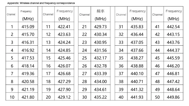
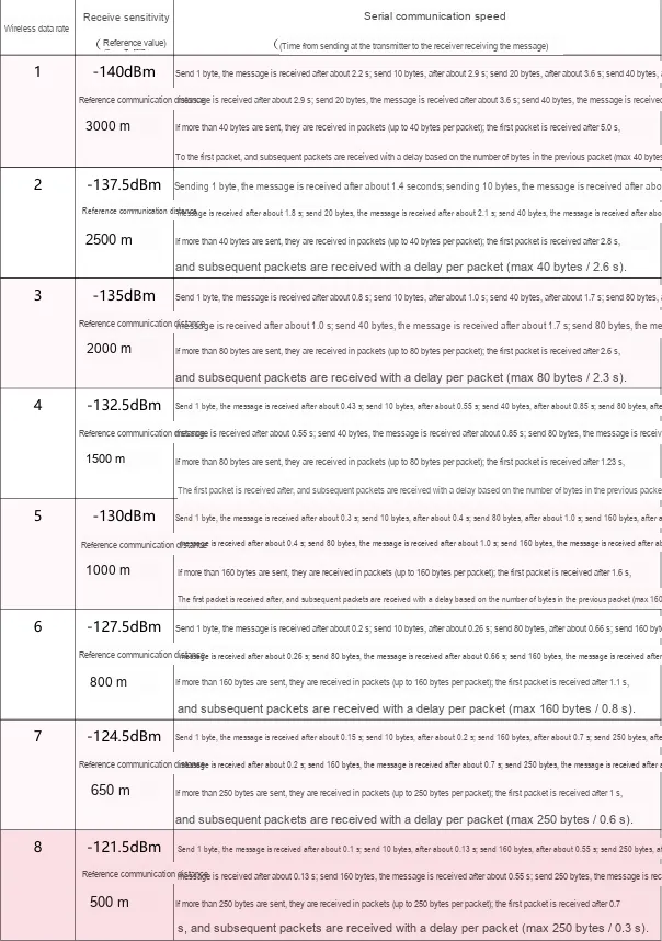
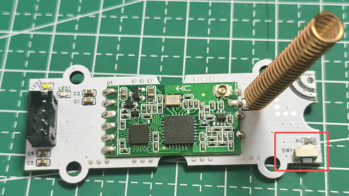
Press the SW1 buttons on both modules to enter AT mode, then run the sample code simultaneously to complete module initialization:
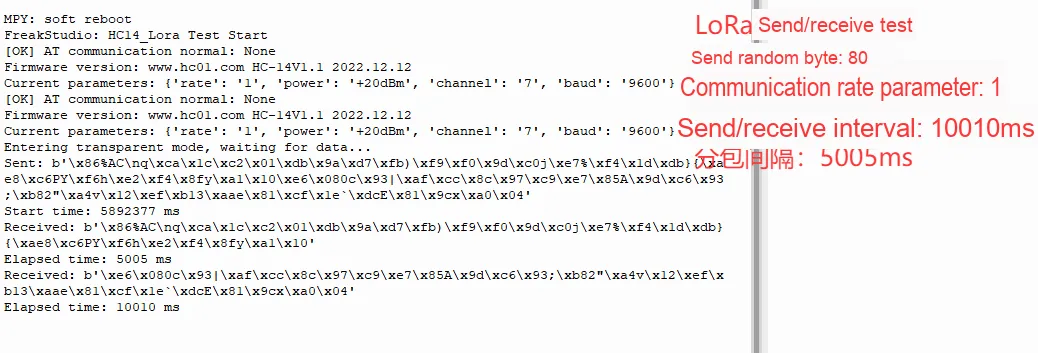
If the following output appears, it indicates that the module initialization setup has been successfully completed; at this point, the interrupt will print the current parameters, and you need to ensure that the parameters from the two outputs are completely identical. After the parameters are successfully displayed and their content matches, you can release the button.

Depending on the different parameters configured, the output is as follows:
Packet reception will be performed in case the rate requirement is exceeded
The following lists different rates, which can be used to compare the interval difference between transmission and reception.
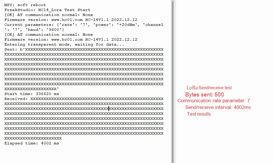
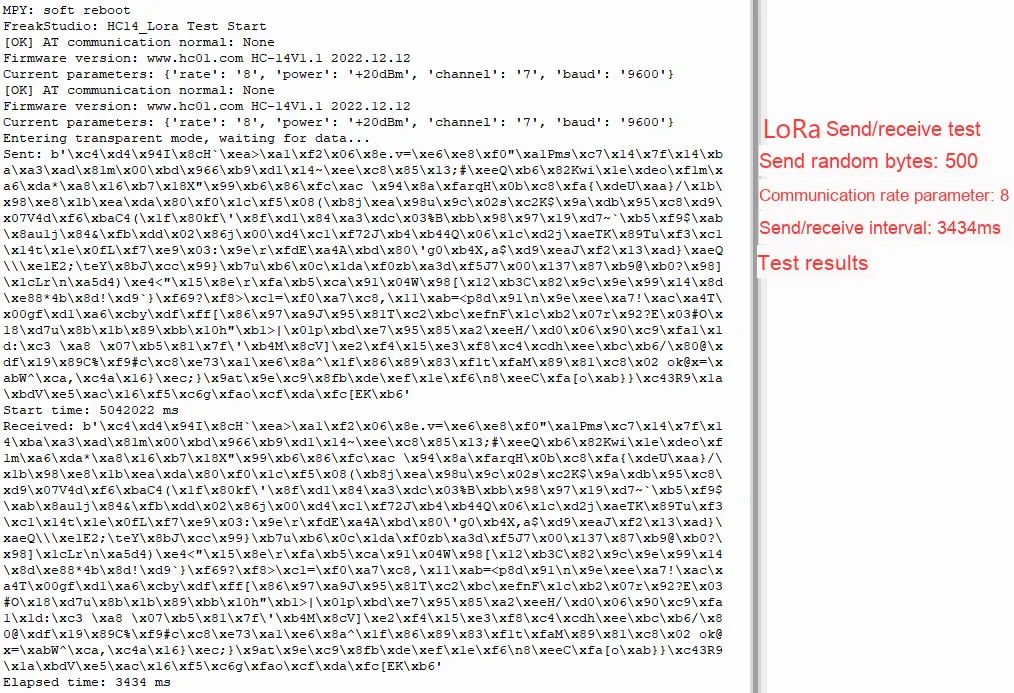
It can be seen that the data at the transmitting end and the receiving end are consistent.
We will first complete the code flashing, then open the terminal and connect to the main control device via the mpremote tool; next, connect the two LoRa modules to the UART0 interface, press the SW1 buttons on both modules to enter the AT mode to finish module initialization. The specific functions of the code are as follows:
# Import the time module, for possible later delay operations
import time
# Import the UART (serial port) and Pin classes from the machine module
from machine import UART, Pin
# Import the driver class for the HC14 LoRa module
from hc14_lora import HC14_Lora
# Adjust the TX/RX pins to match the actual hardware wiring; initialize UART0: baud rate 9600, TX on GPIO16, RX on GPIO17
uart0 = UART(0, baudrate=9600, tx=Pin(16), rx=Pin(17))
# Create an HC14_Lora instance, binding the initialized UART0 to the LoRa module
hc0 = HC14_Lora(uart0)
# Configure the LoRa module communication channel to 7
hc0.set_channel(7)
# Configure the LoRa module transmission rate (refer to the module manual for the specific rate)
hc0.set_rate(7)
# Configure the LoRa module transmit power to 20dBm
hc0.set_power(20)
# Query the configured parameters
hc0.get_params() 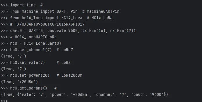
After the parameters of the two LoRa modules are successfully configured, connect one of the modules to a computer via a TTL -to-serial port module, and open the serial port debugging software XCOM, XCOM parameter configuration is as follows
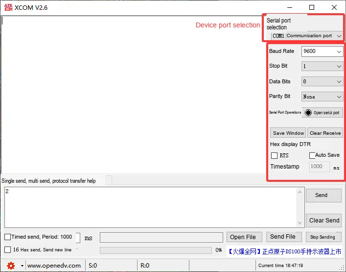
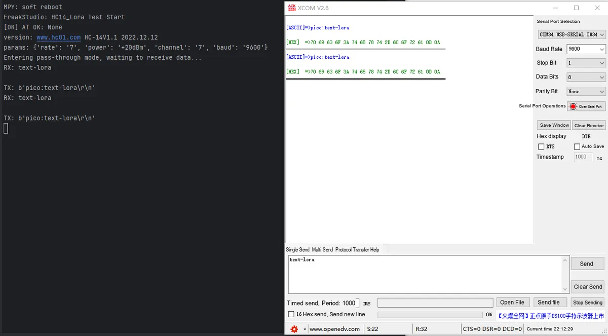
Press SW1 while running main.py, and the firmware version and configured module parameters will be printed at this time:

On the computer side, XCOM the data sent in the serial port debugging software is transmitted via TTL to one of the LoRa modules, then the other module transmits the data to the main control board through LoRa wireless communication; after receiving the data, the main control board will feed it back and print it on the terminal.
QQ20251210-221333.mp4 1.9 MB
IV. Drivers
hc14_driver.zip 13 KB
5. BOM & Recommended Alternative Parts
None.
VI. Revision History
Document Version | Date of Revision | Modifier | Modify Content |
v1.0 | 2025-10-24 | Li Zisheng | Initialize the document The BOM sheet has not been finally checked, the driver has not been re-verified, and the 3.3 application experiment Not yet specified. |
v1.1 | 2025-12-29 | Li Zisheng | Added application experiments and production files |
v1.2 | 2025-12-31 | Xin Ruili | Create an open version of the document based on the internal document version v1.1. |
v1.3 | 2026-03-29 | Xin Ruili | Modified the application experiment section. |
VII. Relevant Materials
7.1 Chip Datasheet
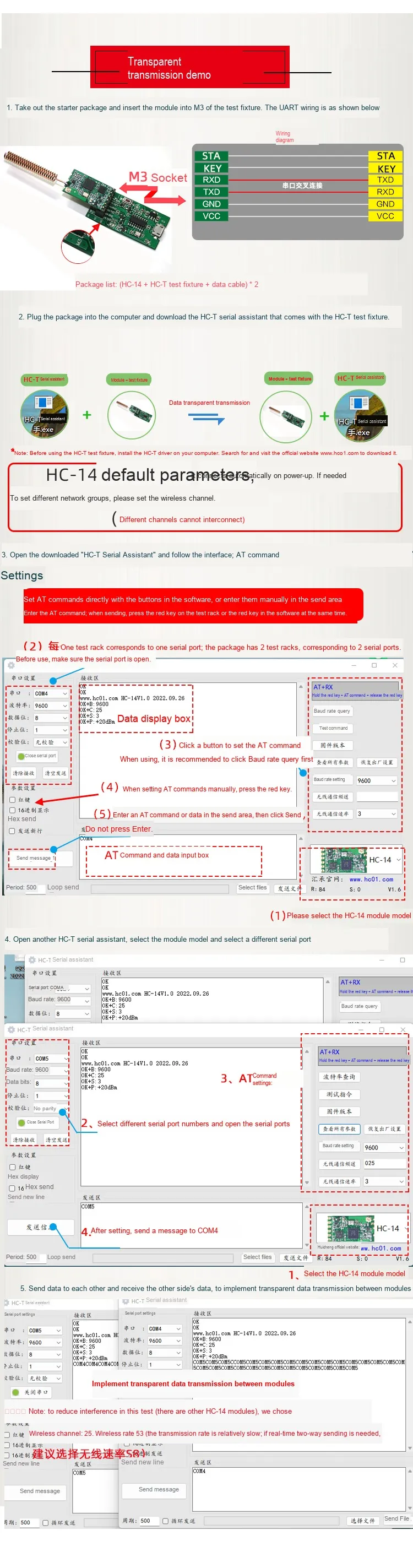
HC-14 User Manual V1.1_20250603.pdf 1.1 MB
PCB footprint:
HC-XX-220926.LIB 208 KB
Related Software:
HC-T Serial Assistant V1.7.2(2023.3.10).exe 462 KB
HC-T Drivers.rar 175 KB
7.2 Unique Icons for PCB Silk Screen