Contents
- I. Module Introduction
- II. Introduction to Main Chips
- 2.1 Chip Overview
- 2.2 Pin Definition
- 2.3 Functional Block Diagram
- 2.4 Performance Parameters
- 2.5 Reference Circuit
- 2.6 Chip Configuration
- 2.7 Communication Interfaces and Related Protocols
- 2.8 PCB Routing Notes
- 3. Instructions for Circuit Engineering and Module Usage
- 3.1 Circuit Source Engineering
- 3.2 Module Usage Instructions
- 3.3 Application Experiment
- IV. Drivers
- 5. BOM & Recommended Alternative Parts
- VI. Revision History
- VII. Relevant Materials
- 7.1 Chip Datasheet
- 7.2 Unique Icons for PCB Silk Screen
I. Module Introduction
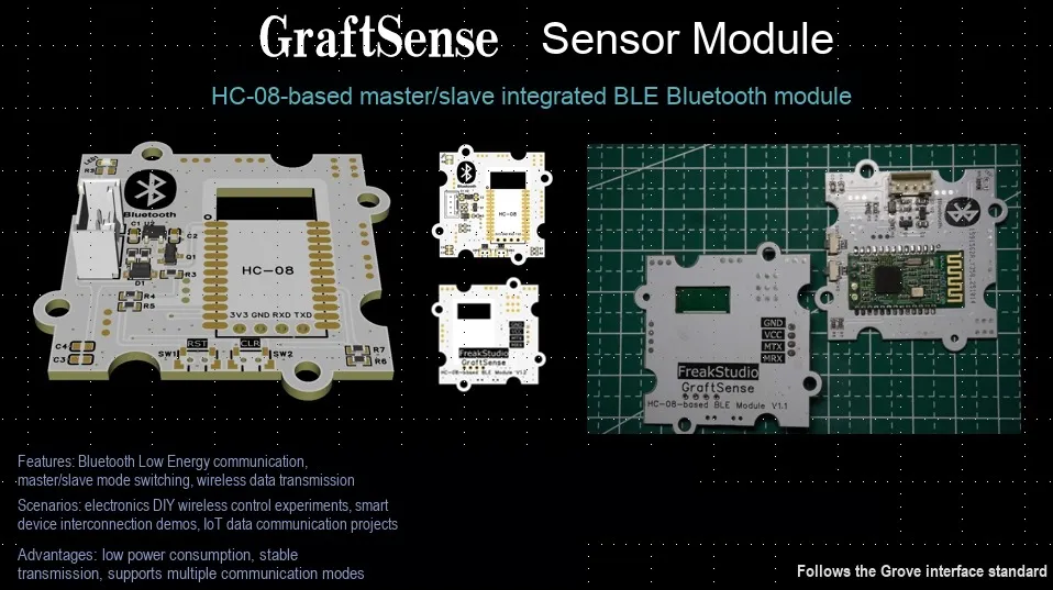
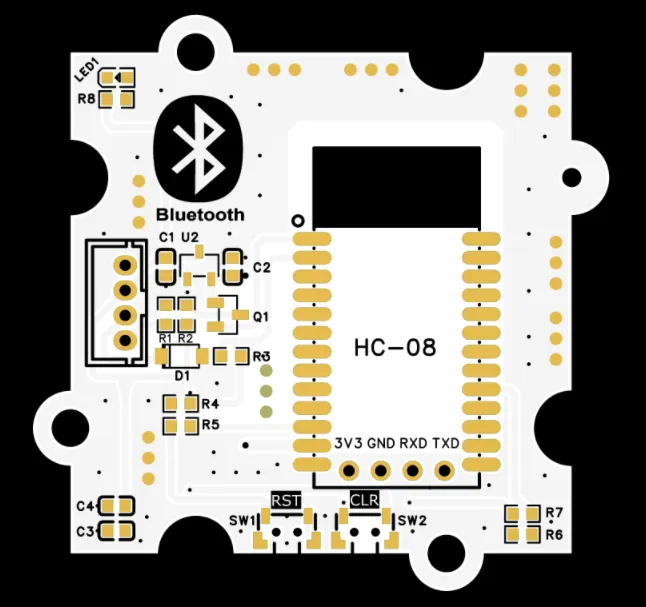
Master-slave integrated BLE Bluetooth module based on HC-08 adopts HC-08 Bluetooth 4.0 BLE serial port module to implement Bluetooth communication function. The module is equipped with a level conversion circuit, which is compatible with + 3.3V and + 5V level communication. It also comes with two side buttons for module reset and host memory clearing functions. The Bluetooth communication of this module is based on the BLE 4.0 protocol and supports master-slave integrated mode. The recommended operating voltage of VIN is + 5V, which is suitable for scenarios such as the Internet of Things and embedded interaction that require BLE Bluetooth communication.
II. Introduction to Main Chips
This module does not use an independent chip, and instead adopts HC-08 Bluetooth serial communication module design.
2.1 Chip Overview
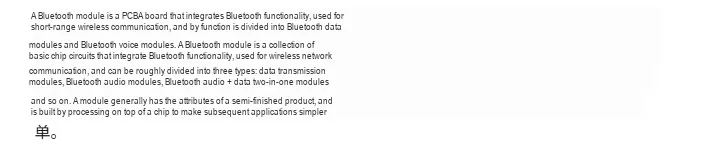
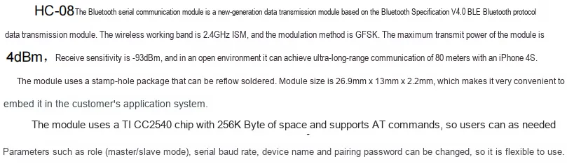
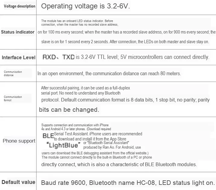
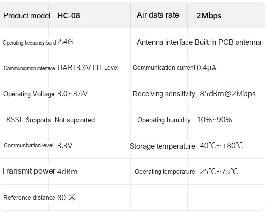
HC-08 Bluetooth module is a low-power Bluetooth serial port module supporting the BLE 4.0 protocol. It features a compact package design and integrates a Bluetooth radio transceiver circuit and a protocol processing unit; its operating voltage ranges from 2.0V to 3.6V, the communication baud rate can be configured between 1200-115200bps with a default value of 9600bps, the receiving sensitivity reaches -93dBm@1Mbps, the maximum transmit power supports 4dBm, it can communicate effectively with iPhone 4s up to 80 meters in open areas, and the operating temperature ranges from -25°C to + 75°C;It supports master-slave integrated mode switching, and enables data interaction with external devices via UART serial port, making it suitable for scenarios requiring low-power wireless communication such as IoT terminals, smart homes, and portable devices.
2.2 Pin Definition
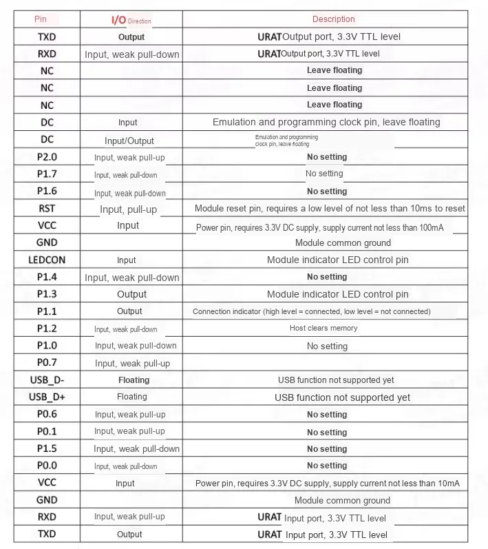
2.3 Functional Block Diagram
Since the HC-08 Bluetooth serial communication module does not have a detailed functional block diagram provided by the official, no functional block diagram is presented in this subsection.
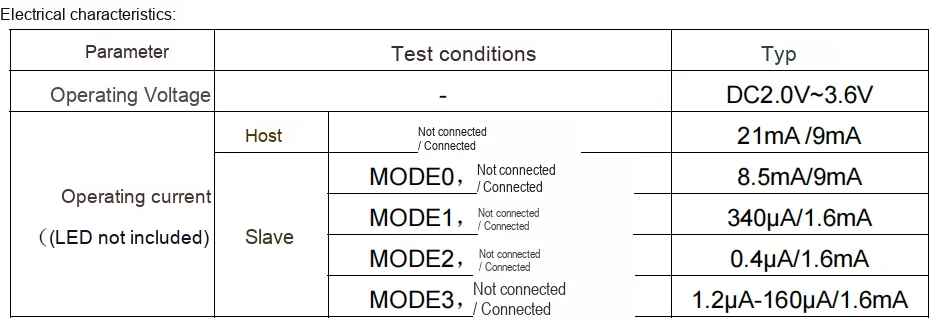
2.4 Performance Parameters
The following table lists the main performance parameters of the HC-08 module:
2.5 Reference Circuit
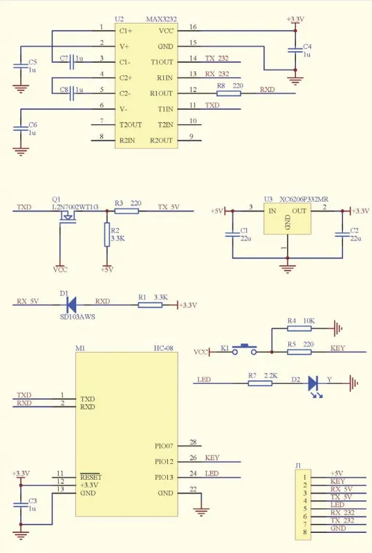
2.5.1 Level Shifting and Serial Communication Section
- Components: MAX3232 (
U2), capacitorsC5,C6,C7,C8(1μF), resistorR8(220Ω) - Function: MAX3232 is an RS232 level conversion chip that converts the TTL level of
HC-08toRS232level, enabling communication with RS232 devices such as host computers;C5,C6,C7, andC8are peripheral supporting capacitors for the chip to ensure the stability of level conversion;R8is a current-limiting resistor that protects signal transmission of the RX_232 interface.
2.5.2 5V and 3.3V Level Conversion Section
- Components:
Q1(LN7002WT1G),R2(3.3kΩ),R3(220Ω);D1(SD103AWS),R1(3.3kΩ) - Function:
Q1forms an N-channel MOSFET circuit to realize the level conversion of the TX signal from 3.3V to 5V (TX_5V);D1is a Schottky diode that realizes the level conversion of the RX signal from 5V to 3.3V (RX_3.3V), ensuring bidirectional communication between the HC-08 (3.3V logic) and 5V logic devices.
2.5.3 DC-DC Power Conversion Section
- Components:
U3(XC6206P332MR), capacitorsC1,C2(22μF) - Function: XC6206 is an
LDOregulator chip that converts + 5V to a stable + 3.3V to supply power to theHC-08Bluetooth module;C1andC2are input and output filter capacitors that filter out power supply noise and ensure power supply stability.
2.5.4 HC-08 Bluetooth Module Section (M1)
- Device: HC-08 master-slave integrated BLE Bluetooth module, capacitor
C3(1μF) - Function:
HC-08is a core functional component that transmits and receives data with external circuits via TXD and RXD, realizing master-slave integrated communication of BLE Bluetooth 4.0;C3is a power supply decoupling capacitor that stabilizes the power supply ofHC-08.
2.5.5 Key and Indicator Section
- Components: Pushbutton
K1, resistorsR4(10 kΩ),R5(220 Ω);D2, resistorR7(2.2 kΩ) - Function:
K1,R4andR5form a key circuit, and pressing the key realizes the function of clearing the memory of the host; R7 is the current-limiting resistor of the power indicator D2, which is used to ensure the normal operation of the power indicator.
2.5.6 External Interface Section (J1)
- Device: Interface
J1 - Function: Provides
+ 5Vpower input,KEYbutton input,RX_5V(5V logic RX),TX_5V(5V logic TX),RX_232(RS232 logic RX),TX_232(RS232 logic TX),GNDand other interfaces to realize multi-type signal interaction between the module and external devices.
2.6 Chip Configuration
This module is of Plug and Play type, requiring no hardware configuration or software register setup. The HC-08 module and the microcontroller rely entirely on data interaction via the serial port Communication Protocol for their communication.
2.7 Communication Interfaces and Related Protocols
2.7.1 Brief Introduction to Serial Port Transparent Transmission Principle
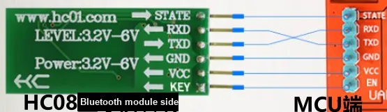
With the HC-08 Bluetooth module inside the unit serving as the core, the data stream sent by external devices (such as MCU and PC) via the serial port is directly encapsulated into UART BLE 4.0 protocol data frames for wireless transmission; meanwhile, the received BLE wireless data frames are parsed and restored into a UART serial data stream to be output to external devices.During the entire process, the module does not need to perform any protocol parsing or modification on the serial port data, and only completes the bidirectional transparent conversion of serial port electrical signals → Bluetooth wireless signals → serial port electrical signals, which realizes wireless communication between serial port devices, allowing traditional serial port devices to quickly access the Bluetooth wireless network without modifying their original communication logic.
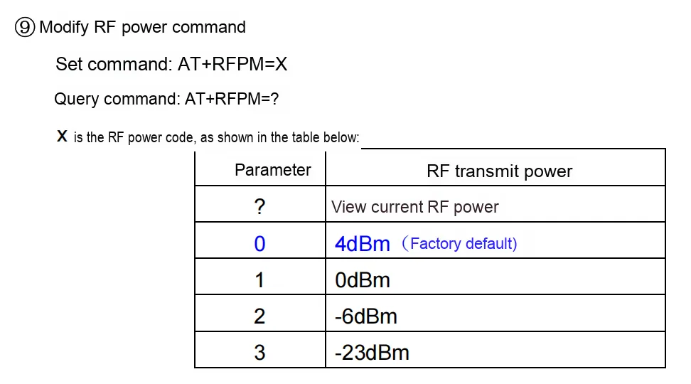
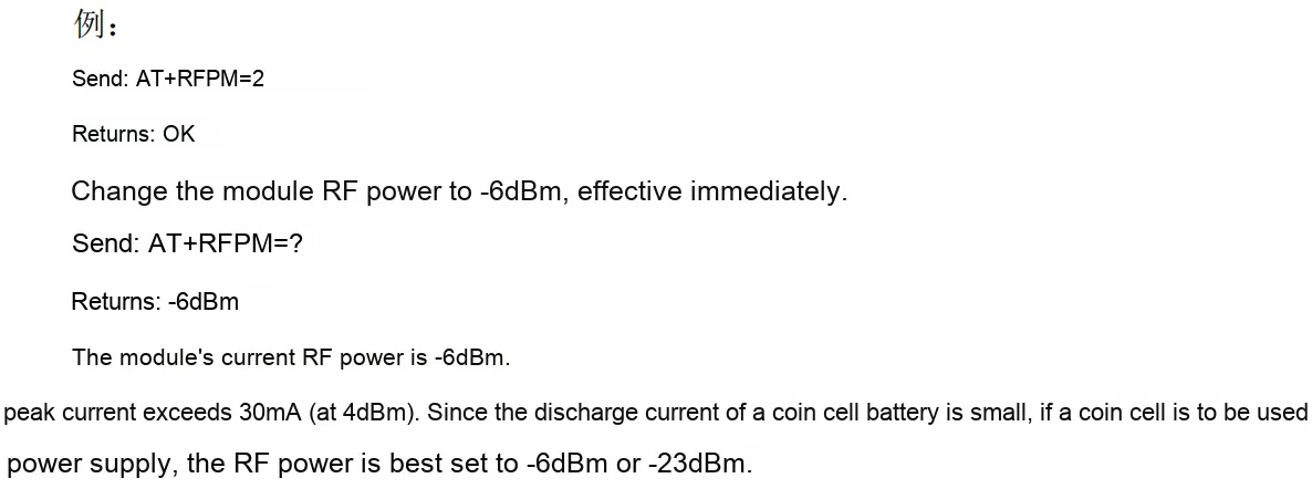
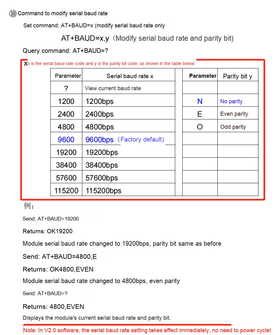
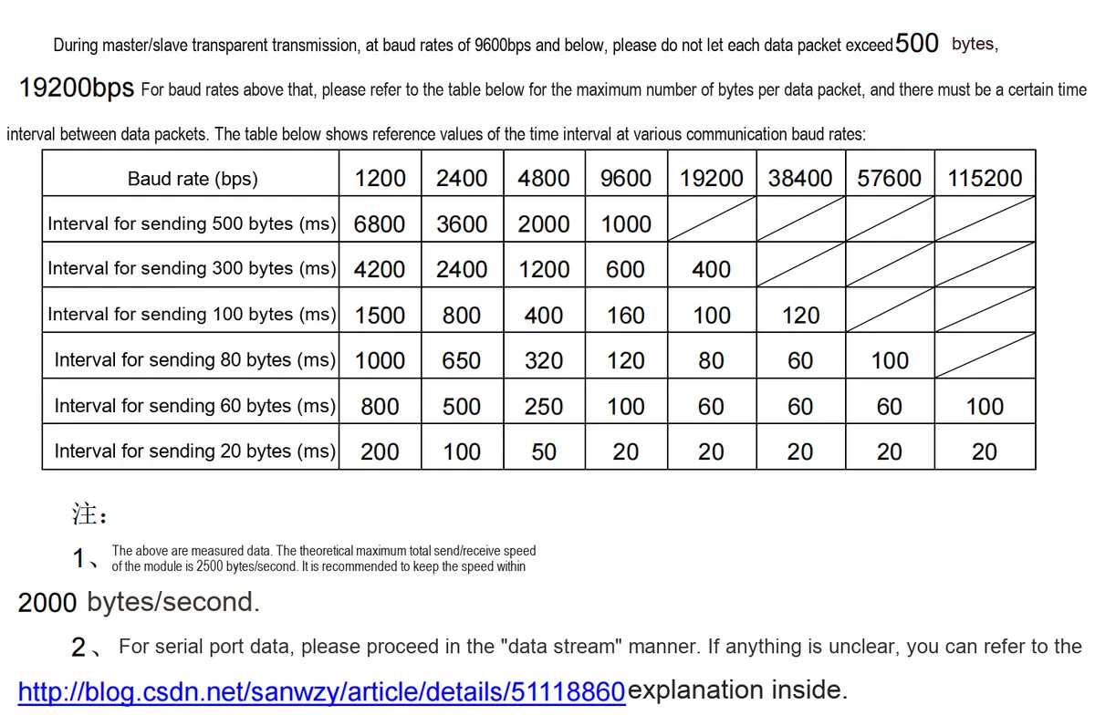
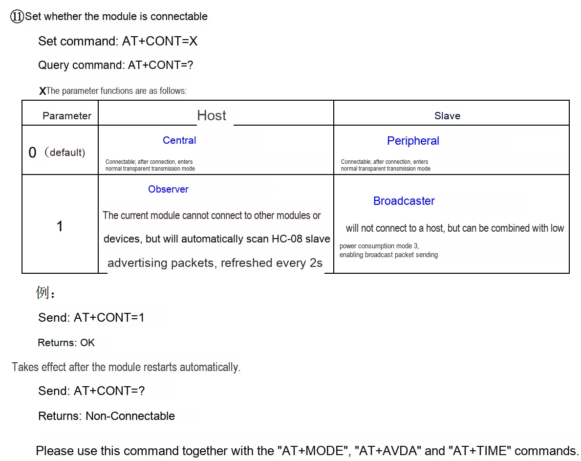
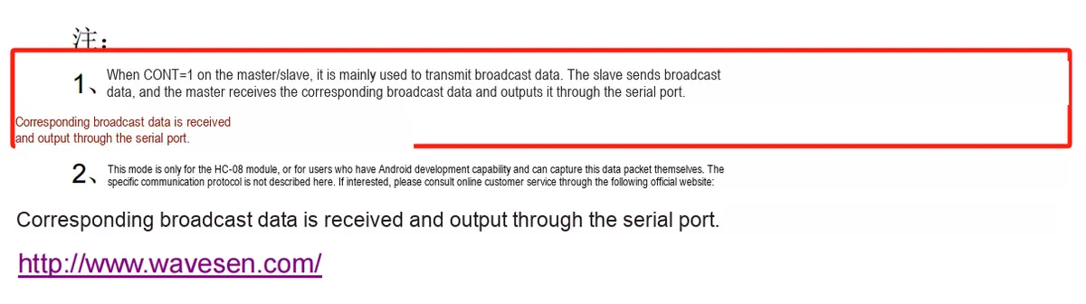
2.7.2 AT Command Related
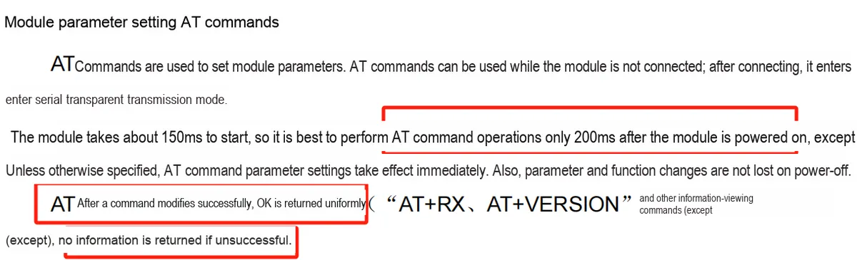
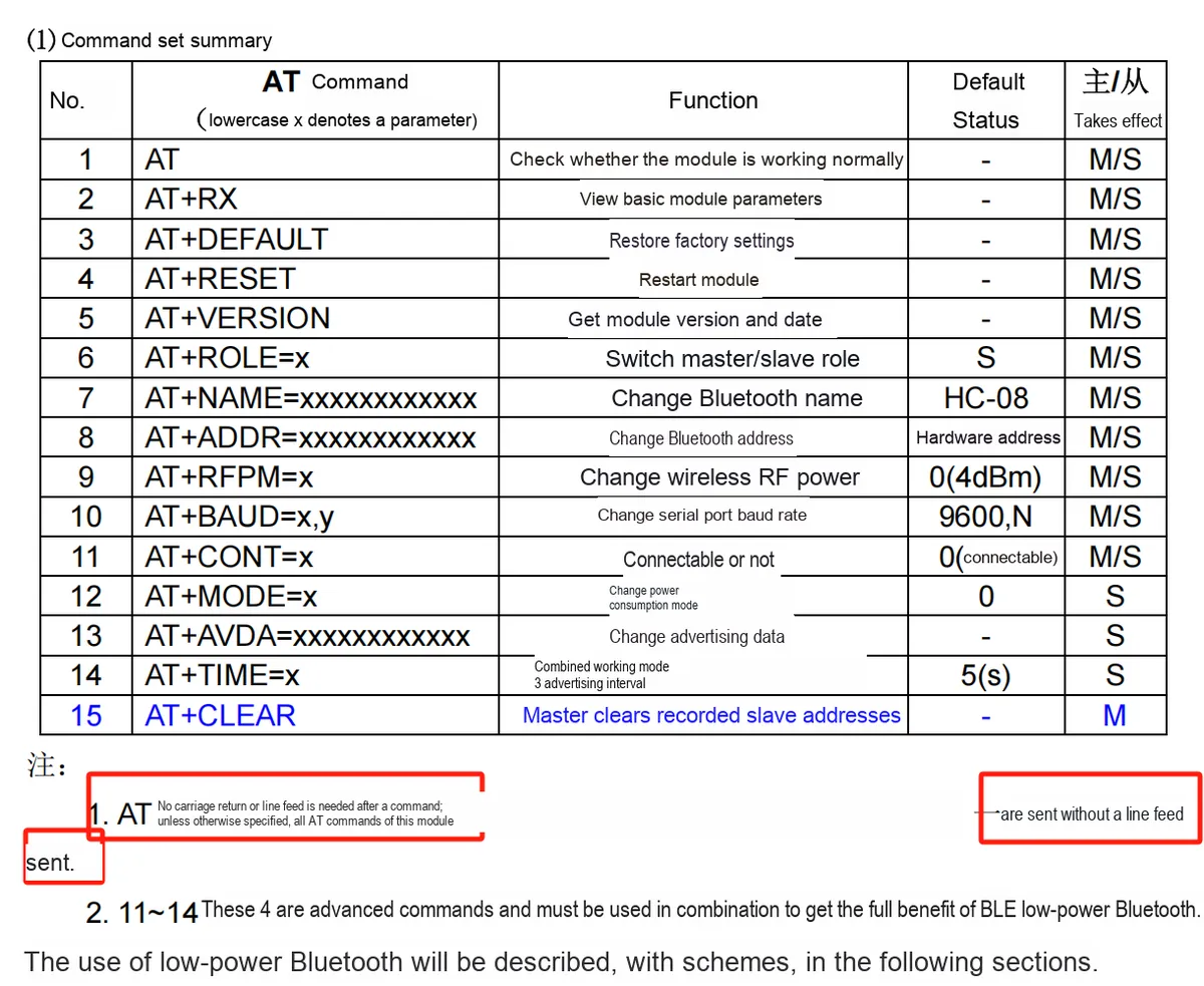
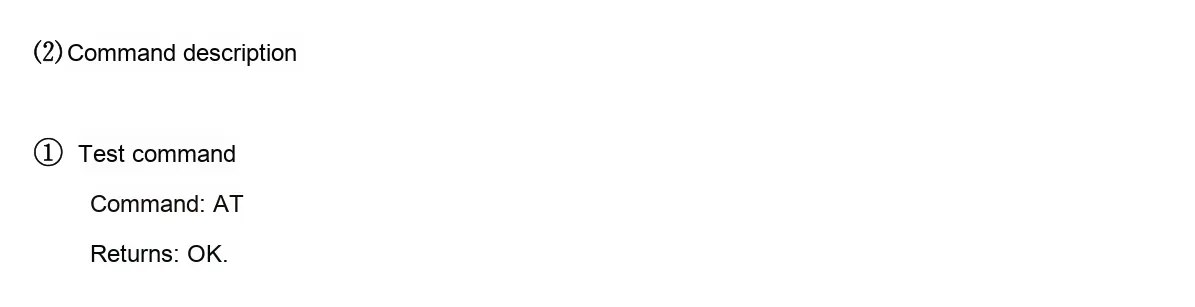
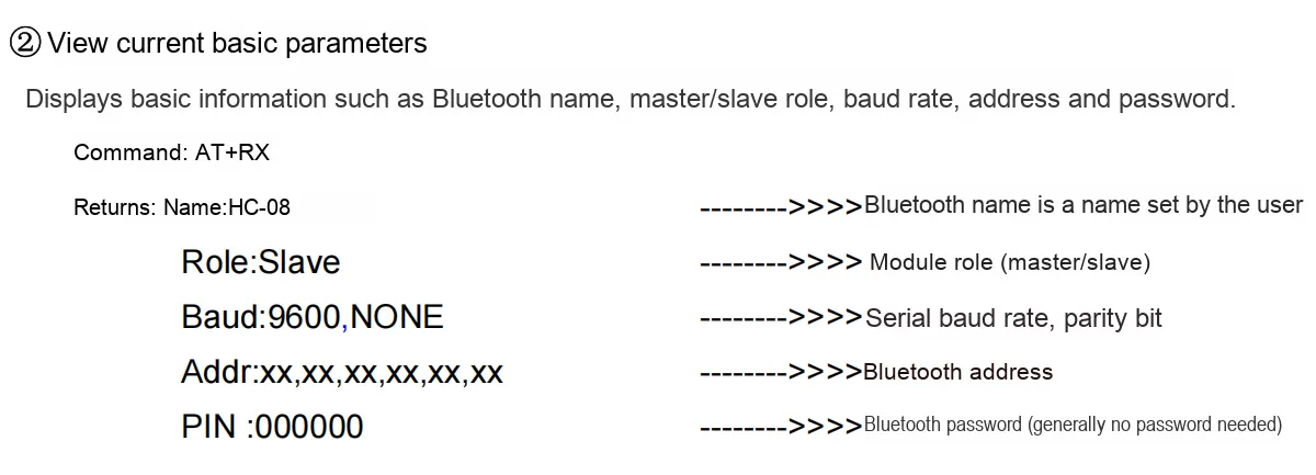

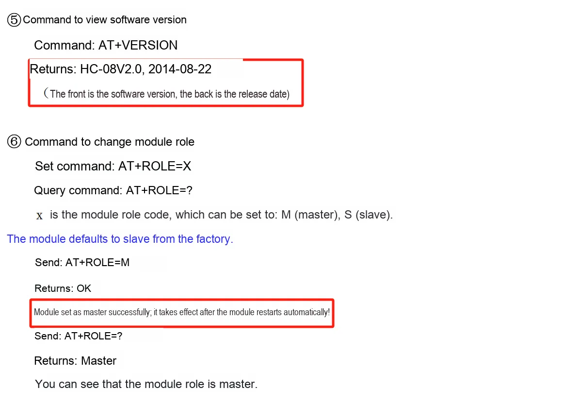
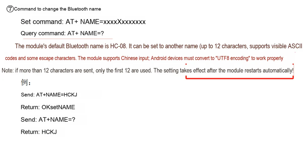
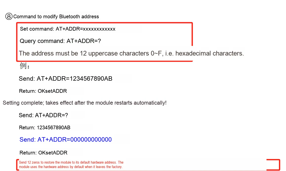
2.8 PCB Routing Notes
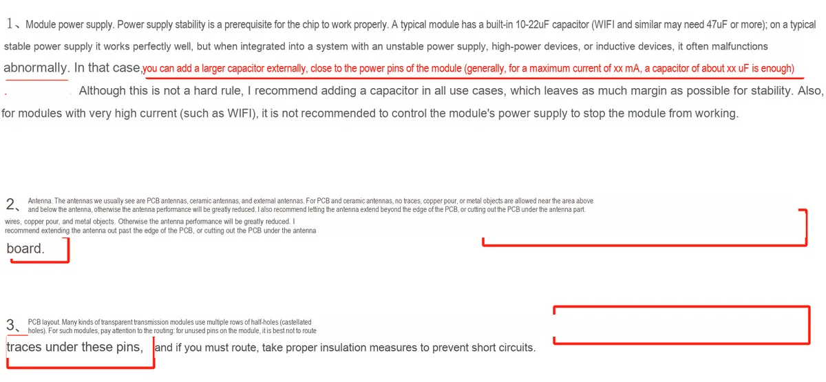
The PCB under the antenna section needs to be hollowed out!!!!!
3. Instructions for Circuit Engineering and Module Usage
3.1 Circuit Source Engineering
To obtain the circuit source project, please follow the official account [Freak Embedded]
3.2 Module Usage Instructions
The schematic diagram of this module is shown below:
SCH_Schematic1_Master-Slave Integrated BLE Bluetooth Module Based on HC-08-V1.1.0_2025-10-24.pdf 3.6 MB
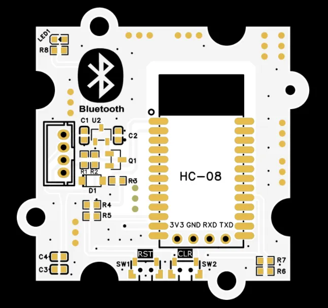
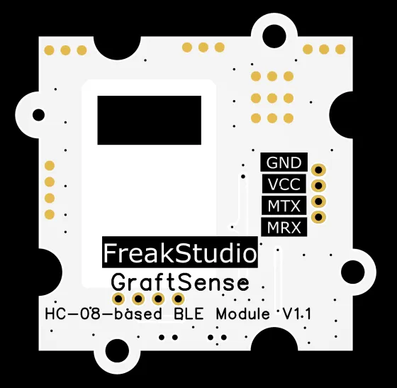
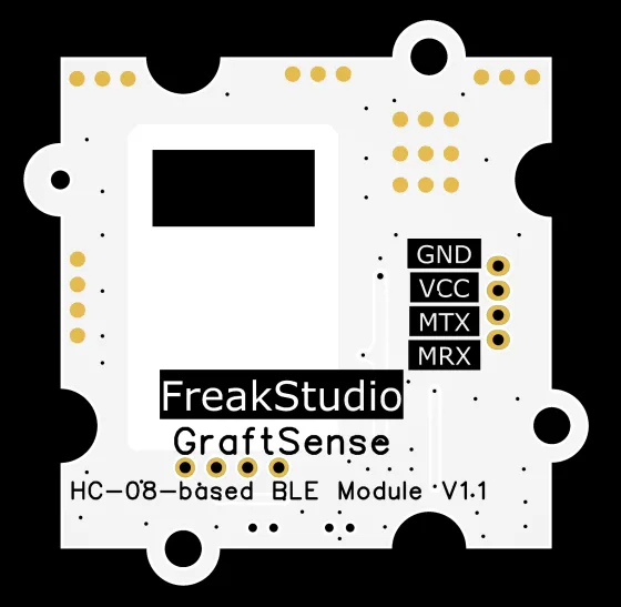
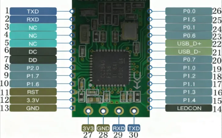
In this module, MRX (corresponding to the UART RXD pin of the MCU) is physically connected to the HC-08 ’s R1OUT pin, and MTX (corresponding to the UART TXD pin of the MCU) is physically connected to the HC-08 ’s T1IN pin. This is because UART serial communication follows the "cross transmit-receive" rule — the transmit terminal (TX) of each communication party must be connected to the receive terminal (RX) of the counterpart; this design ensures correct bidirectional transmission of UART serial data between the MCU and HC-08 via the UART interface.
It is particularly important to note that when using this module, MRX should be directly connected to the RXD pin of the MCU's UART, and MTX should be directly connected to the TXD pin of the MCU's UART; do NOT cross-connect them under any circumstances.
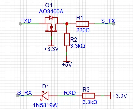
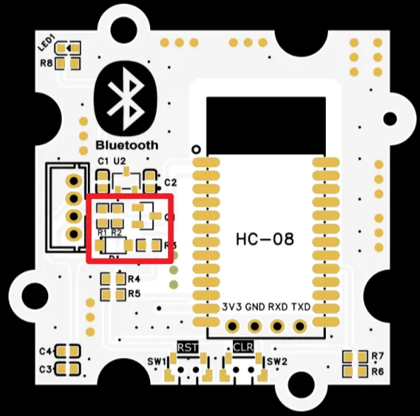
HC-08 Bluetooth module is compatible with TTL communication levels of + 5V and + 3.3V.
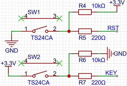
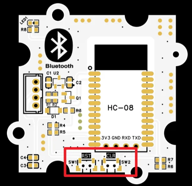
As shown in the figure, the module reserves two tact switches, of which SW1 is used for module reset, and SW2 is used for the host to clear the slave memory.
3.3 Application Experiment
Here, we use the GraftPort-RP2040 development board for testing, and connect the HC-08 based master-slave integrated BLE Bluetooth module to communicate with the main controller via the UART interface.
Here, we first use the HY2.0-4P cable to connect the module to the GraftPort-RP2040 development board's UART0 interface:
The module connections are shown in the following table:
Development Board Pins | Module Pins | Description |
Pin 16 |
|
|
Pin 17 |
|
|
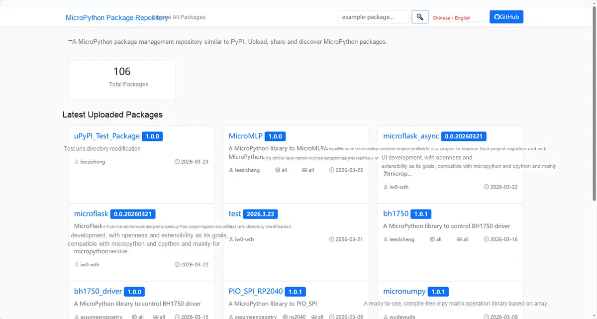
Here, we need to search for the relevant driver packages on uPyPI: https://upypi.net/zh/
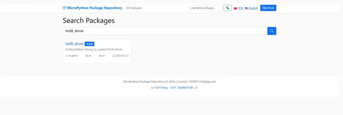
Enter hc08_driver to search, and the following will be displayed:
Click to copy the local installation command:
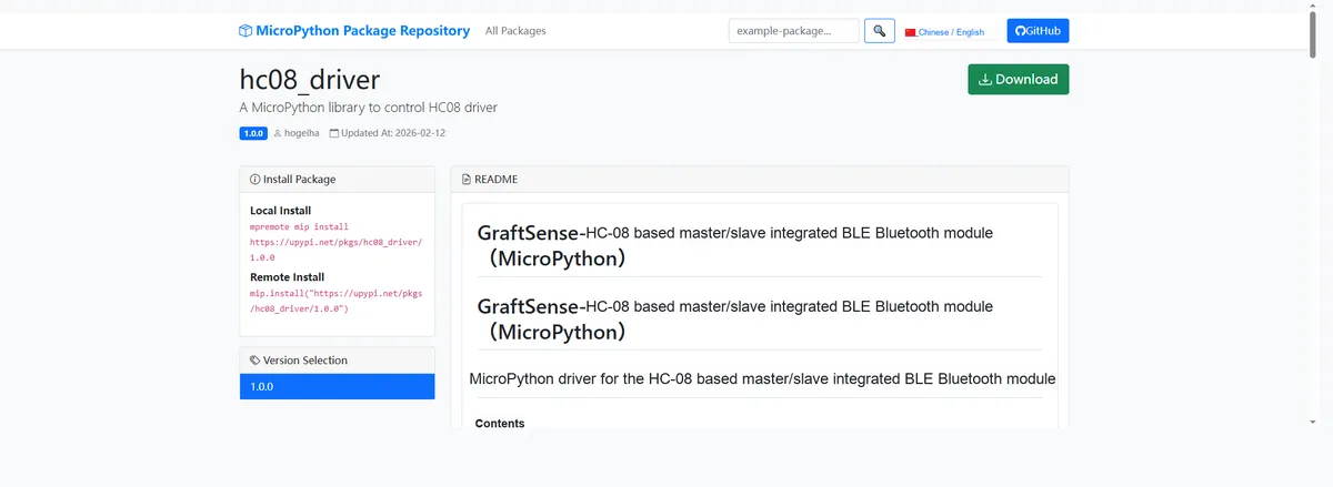
Here, we can use the mip tool to import module driver library code. Below are the usage commands for the mpremote tool:
mpremote mip install github:FreakStudioCN/GraftSense-Drivers-MicroPython/communication/hc08_driverImport the HC-08 Bluetooth Serial Communication - MicroPython Driver Code, then copy the following main.py code into our project:
# Python env   : MicroPython v1.23.0
# -*- coding: utf-8 -*-
# @Time    : 2025/9/5 10:11 PM
# @Author  : ben0i0d
# @File    : main.py
# @Description : hc08 test file

# ======================================== Import Modules =========================================

import time
from machine import UART,Pin
from hc08 import HC08

# ======================================== Global Variables ============================================

# ======================================== Functions ============================================

# ======================================== Custom Classes =============================================

# ======================================== Initialization configuration ===========================================

# Power-on delay of 3 s
time.sleep(3)
print("FreakStudio:HC08 test")

# Initialize UART communication (adjust TX/RX according to the actual hardware wiring)
uart0 = UART(0, baudrate=9600, tx=Pin(16), rx=Pin(17))
# Create an HC14_Lora instance
hc0 = HC08(uart0)

# ========================================  Main Program  ===========================================

ok, resp = hc0.get_name()
print(f'hc0 Name   :{resp}')
ok, resp = hc0.get_version()
print(f'hc0 Version:{resp}')
ok, resp = hc0.get_role()
print(f'hc0 Role   :{resp}')

while True:
    # Block and receive transparent transmission data
    ok, data = hc0.recv_data(timeout_ms=200)
    # When data is received successfully, print data and send it back
    if ok:
        print(data)
        hc0.send_data("get data:")
        hc0.send_data(data)
    time.sleep(0.05)
Burn the code, open the terminal, and use the mpremote tool to connect to the main controller, then use the encapsulated function to perform module AT settings in the REPL interface
>>> import time
>>> from machine import UART,Pin
>>> from hc08 import HC08
>>> #  UART  TX/RX
>>> uart0 = UART(0, baudrate=9600, tx=Pin(16), rx=Pin(17))
>>> #  HC14_Lora
>>> hc0 = HC08(uart0)
>>> hc0.check()
(True, 'OK')
>>> hc0.factory_default()
(True, 'OK')
>>> hc0.get_rx()
(True, {'Addr': '48,70,1E,9C,C1,E3', 'Role': 'Slave', 'PIN': '000000', 'Name': ''HC-08', 'Baud': '9600,NONE'})
hc0.check (): Check whether the module responds to AT commands normally. If the return value is(True, 'OK'), it indicates that the module communication is normal.hc0.factory_default (): Restore the factory settings of the module and return(True, 'OK')to indicate that the reset is successful (the previous custom configuration will be cleared).hc0.get_rx (): Reads the current parameters of the module, and the returned dictionary contains key information:Addr: Bluetooth MAC address (48,70,1E, 9C, C1, E3);Role: Operating mode (Slave, slave mode);PIN: Pairing password (000000);Name: Device name (HC-08);Baud: Serial port baud rate and parity mode (9600, NONE, i. e. 9600 baud rate, no parity).
We need to install the mobile phone Bluetooth Debugger APP, and the following will give a brief demonstration of its basic functions.
Bluetooth_Debugger.apk 2.3 MB
- Enable the Bluetooth and location services on your mobile phone, open the APP, tap the scan button, and you will see the list of currently connectable Bluetooth devices.
- Based on the previously output module information from the terminal (the Bluetooth name is
HC-08, corresponding to theMACaddress), findHC-08in the device list, click the+sign on the right to select this device, and the connection will be completed. - After the connection is successful, switch to the "Dialogue Mode", then you can enter content in the input box and send it to realize communication and interaction with the Bluetooth module.
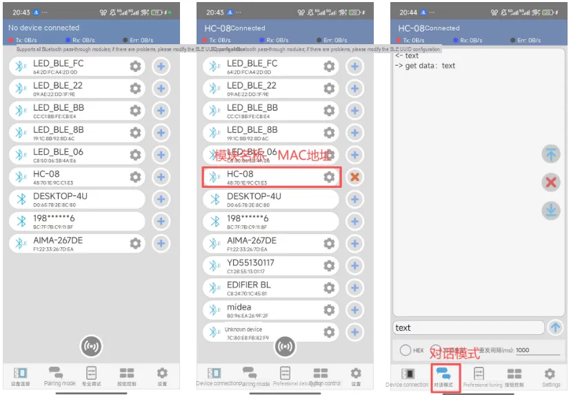
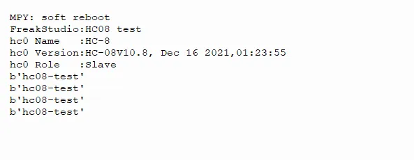
It can be seen that our Bluetooth module sends the information received from the mobile phone Bluetooth APP to the main control through the serial port, and at the same time, the terminal prints and outputs the content:
IV. Drivers
hc08_driver.zip 12 KB
5. BOM & Recommended Alternative Parts
None.
VI. Revision History
Document Version | Date of Revision | Modifier | Modify Content |
v1.0 | 2025-10-24 | Zero Kōkō | Initialize the document |
v1.1 | 2025-12-29 | Li Zisheng | Added application experiments and production files |
v1.2 | 2025-12-31 | Xin Ruili | Create an open version of the document based on the internal document version v1.1. |
v1.3 | 2026-03-29 | Xin Ruili | Modified the application experiment section. |
VII. Relevant Materials
HC-08 One-Minute Tutorial and Software.rar 4.4 MB
7.1 Chip Datasheet
HC-08 User Manual.pdf 444 KB
7.2 Unique Icons for PCB Silk Screen