Contents
- I. Module Introduction
- II. Introduction to Main Chips
- 2.1 Chip Overview
- 2.2 Pin Definition
- 2.3 Functional Block Diagram
- 2.4 Performance Parameters
- 2.5 Reference Circuit
- 2.6 Chip Configuration
- 2.7 Communication Interfaces and Related Protocols
- 2.8 PCB Routing Notes
- III. Circuit Engineering
- 3.1 Circuit Source Engineering
- 3.2 Module Usage Instructions
- 3.3 Application Experiment
- IV. Drivers
- 5. BOM & Recommended Alternative Parts
- VI. Revision History
- VII. Relevant Materials
- 7.1 Chip Datasheet
- 7.2 Unique Icons for PCB Silk Screen
I. Module Introduction
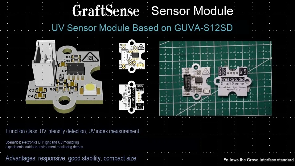
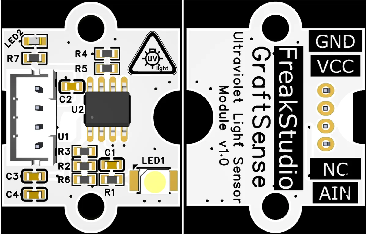
The UV ultraviolet sensor module based on GUVA-S12SD is a device that takes GUVA-S12SD ultraviolet sensor as the core, and is equipped with LM358 operational amplifier to realize signal amplification. It outputs a voltage signal linearly corresponding to the ultraviolet intensity through the analog output interface (AIN), and integrates circuits such as power indicator and filter capacitor, which can accurately collect and process ultraviolet intensity information. It is suitable for scenarios such as environmental monitoring and ultraviolet protection, and provides users with a reliable ultraviolet signal detection solution.
II. Introduction to Main Chips
The core chip of this module is from the South Korean GENUV company, which is the GUVA-S12SD ultraviolet photodiode.
2.1 Chip Overview
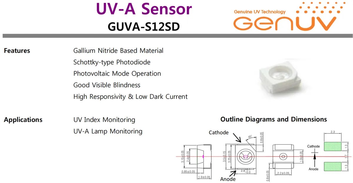
GUVA-S12SD is a Schottky-type ultraviolet photodiode based on gallium nitride material, which operates in photovoltaic mode and features excellent visible-blind characteristics, high responsivity and low dark current. It is suitable for scenarios including UV index monitoring and UV-A lamp monitoring, providing accurate photoelectric conversion solutions for ultraviolet detection applications.
2.2 Pin Definition
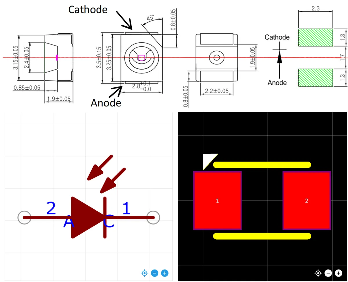
GUVA-S12SD ultraviolet photodiode has two pins, which are the anode (Anode) and the cathode (Cathode) respectively:
- Anode (
Anode): An electrode through which current flows out, which is usually used in circuits to connect to the input terminal of a signal amplification or acquisition circuit. - Cathode (
Cathode): refers to the electrode into which current flows, which needs to form a loop with the circuit to realize the photoelectric conversion and output of ultraviolet signals.
These two pins serve as the core connection terminals for realizing the photovoltaic mode operation and completing ultraviolet photoelectric detection, through which the photocurrent generated by ultraviolet irradiation can be converted into a measurable electrical signal.
2.3 Functional Block Diagram
None.
2.4 Performance Parameters
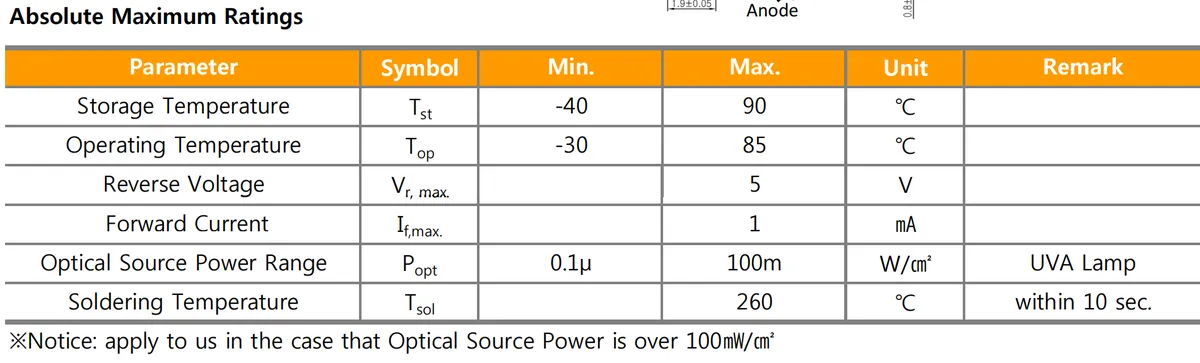
GUVA-S12SD ultraviolet photodiode has the following absolute maximum ratings:
- Storage temperature (
Tₛₜ):-40℃ to 90℃, which is the temperature limit that the device can withstand during storage; exceeding this range may result in permanent damage to the device performance. - Operating Temperature (
Tₒₚ):-30℃ to 85℃, which is the temperature range for normal operation of the device; performance stability cannot be guaranteed if this range is exceeded. - Reverse Voltage (
Vᵣ, max): Maximum 5V, which refers to the highest voltage allowed when the device is reverse-biased; exceeding this value may easily lead to reverse breakdown. - Forward current (
Iբ, max): Maximum 1mA, which is the maximum current allowed during forward conduction; overcurrent will burn out the device. - Light source power range (
Pₒₚₜ): 0.1 μW/cm² ~ 100 mW/cm², which is the UVA light source power range detectable by the device; if it exceeds 100 mW/cm², please consult the manufacturer for a special handling solution. - Soldering temperature (
Tₛₒₗ): 260℃(duration ≤ 10s), which is the maximum temperature that the pins can withstand during soldering; exceeding either the time limit or the temperature limit will damage the device.
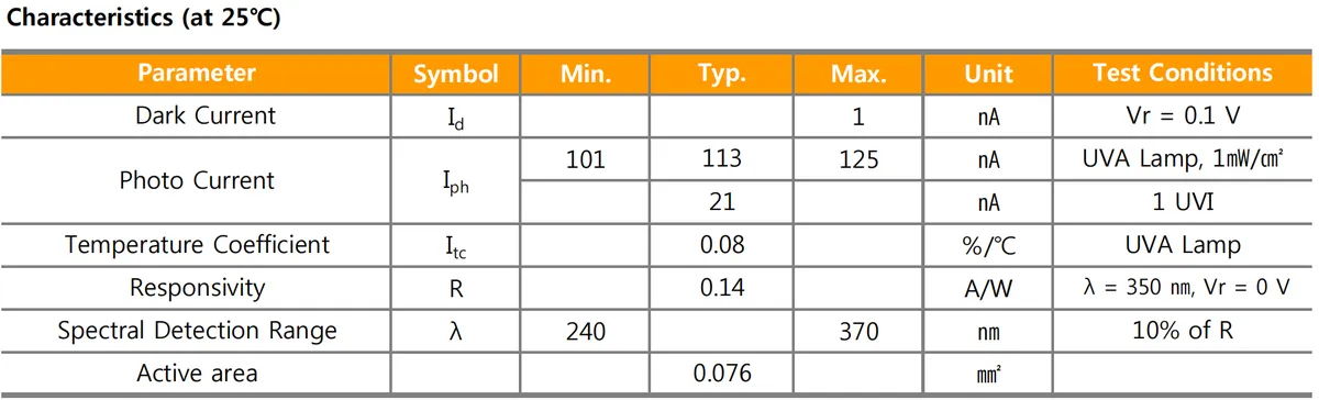
GUVA-S12SD The characteristic parameters at 25°C are as follows:
- Dark current (
Id): Maximum 1 nA, measured under the test condition of reverse voltageVr= 0.1 V. It refers to the leakage current under no light illumination, and a smaller value indicates more stable device performance. - Photocurrent (
Iph):- When irradiated with a
UVAlamp (1 mW/cm²), the current ranges from 101 to 125 nA, with a typical value of 113 nA; - When the
UVindex is 1 (1UVI), the typical value is 21nA, which reflects the current output capability under different ultraviolet intensity levels.
- When irradiated with a
- Temperature coefficient (
Itc): Typical value: 0.08%/°C, tested underUVAlamp, which reflects the rate of change of photocurrent with temperature and is used for temperature compensation. - Responsivity (
R): Typical value is 0.14 A/W, measured under the test conditions of wavelengthλ= 350 nm and reverse voltageVr= 0 V; it represents the current generated per watt of incident optical power and reflects the photoelectric conversion efficiency. - Spectral detection range (
λ): 240~370 nm (with responsivity of 10% as the threshold), covering theUVAand partialUVBbands, which defines the device's sensitive interval to ultraviolet radiation. - Effective Area: Typical value 0.076 mm ², which refers to the actual area involved in photoelectric conversion and affects the light receiving capability.
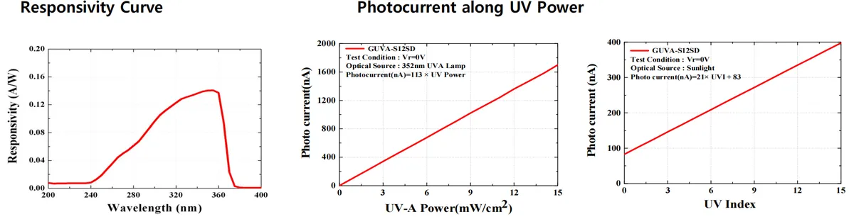
These three charts illustrate the performance characteristics of GUVA-S12SD from different perspectives:
- The left graph (responsivity curve): The horizontal axis represents wavelength (nm), and the vertical axis represents responsivity (A/W), which reflects the photoelectric conversion efficiency of the device in the 200-400nm band. The curve reaches its peak in the 320-360nm range, indicating that it is most sensitive to ultraviolet rays in the
UVAband (especially around 350nm) and meanwhile features excellent visible-blind performance. - Figure (photocurrent vs.
UV-Apower relationship): The horizontal axis representsUV-Apower (mW/cm²), the vertical axis represents photocurrent (nA), and the test conditions are a 352 nmUVAlamp andVr= 0 V. The curve shows a linear relationship, with the formula "Photocurrent (nA) = 113 × UV power", indicating that in this wavelength band, the photocurrent is linearly correlated with the incidentUVpower, which can be used for quantitative detection of the radiation intensity ofUVAlamps. - Right graph (photocurrent vs.
UVindex): The horizontal axis represents theUVindex (UVI), the vertical axis represents the photocurrent (nA), and the test condition is sunlight withVr= 0 V. The curve is also linear, with the formulaPhotocurrent (nA) = 21 × UVI + 83, indicating that under sunlight conditions, the photocurrent has a linear correlation with theUVindex, which can be directly applied to the monitoring and quantification of the UV index.
2.5 Reference Circuit
None.
2.6 Chip Configuration
None.
2.7 Communication Interfaces and Related Protocols
None.
2.8 PCB Routing Notes
None.
III. Circuit Engineering
3.1 Circuit Source Engineering
To obtain the circuit source project, please follow the official account [Freak Embedded]
3.2 Module Usage Instructions
The schematic diagram of this module is shown below:
SCH_GUVA-S12SD-Based UV Sensor Module_v1.0_2025-10-24.pdf 2.1 MB
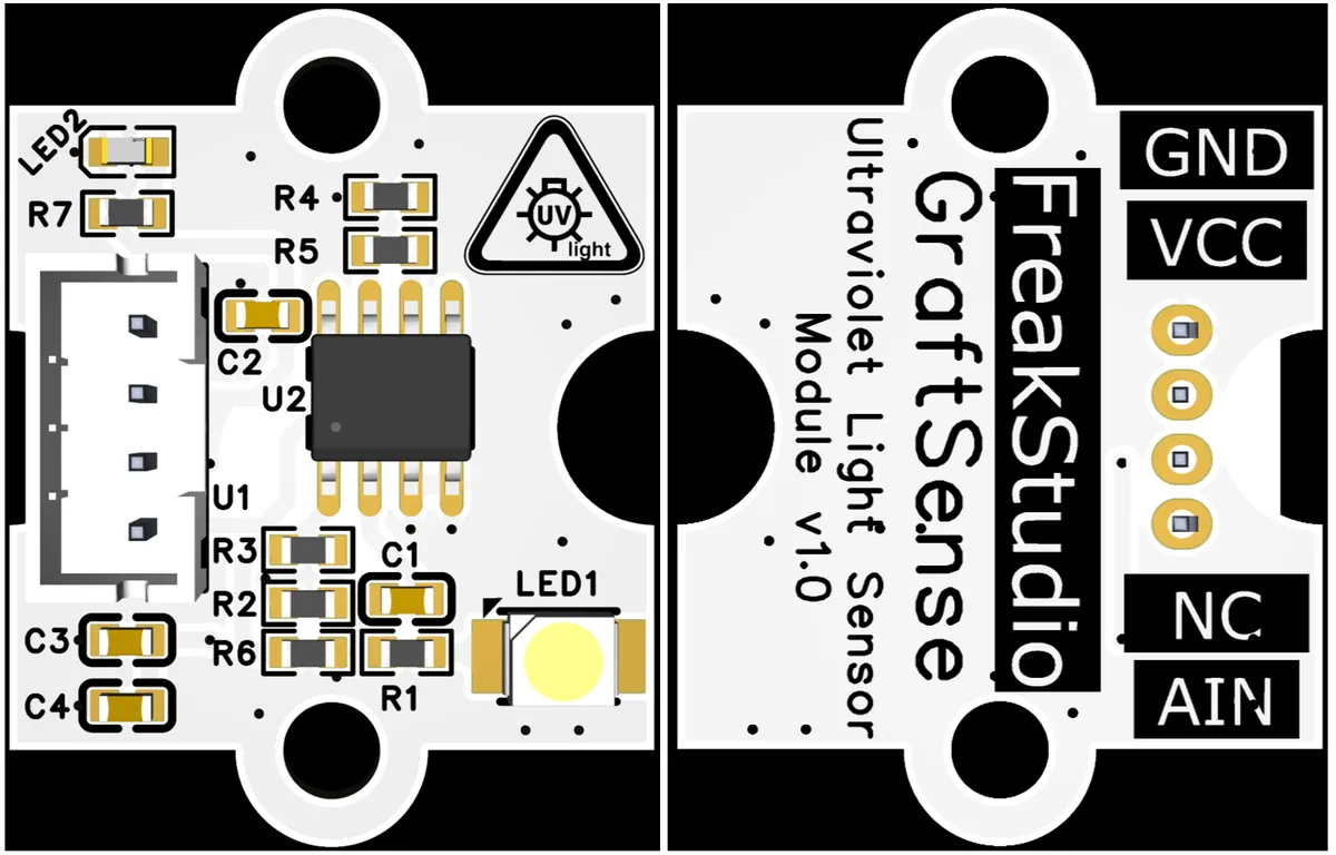
This module provides an analog output interface AIN: The analog voltage signal output by this interface is generated by the photocurrent of the GUVA-S12SD ultraviolet photodiode after being amplified in two stages by the LM358 operational amplifier, and the voltage value is linearly correlated with the ultraviolet intensity. External devices (such as microcontrollers) can collect the signal of this interface via the ADC to realize quantitative detection of ultraviolet intensity or UV index, providing accurate analog feedback for scenarios such as environmental monitoring and ultraviolet protection.
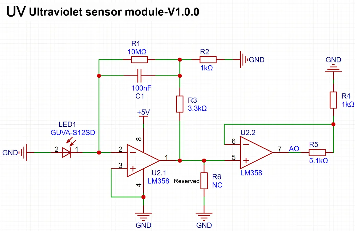
The amplifier circuit we adopt LM358 dual operational amplifier to realize two-stage amplification:
- Stage 1
U2.1converts and amplifiesthe photocurrent of GUVA-S12SDinto a voltage signal through a 10MΩ feedback resistor; - Level 2
U2.2further amplifies the signal amplitude via a non-inverting amplifier circuit, whose gain is set to approximately 6.1 times by 1kΩ and 5.1kΩ resistors.
Finally, it outputs an analog voltage linearly correlated with the ultraviolet intensity, which provides sufficient amplification capability and linear accuracy for subsequent signal acquisition.
3.3 Application Experiment
Here, we use the GraftPort-RP2040 development board for testing, and connect the GUVA-S12SD-based UV ultraviolet sensor module to communicate with the main controller via the AIN interface.
Here, we first use the HY2.0-4P connecting cable to connect the module to the GraftPort-RP2040 development board's AIN0 interface:
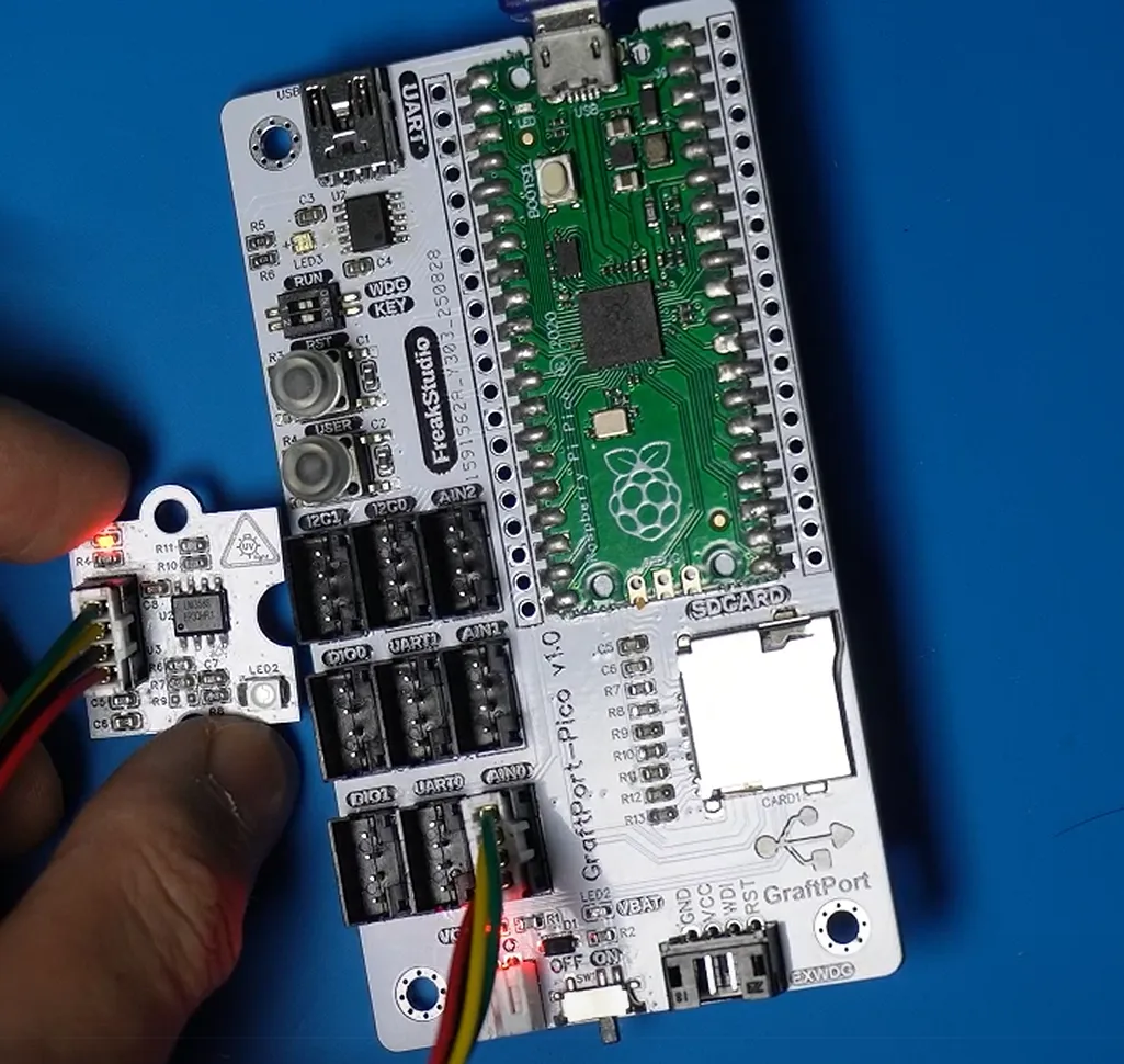
The module connections are shown in the following table:
Development Board Pins | Module Pins | Description |
Pin 26 |
| UV ultraviolet sensor analog output pin |
Pin 19 |
| - |
Here, we need to search for the relevant driver packages on uPyPI: https://upypi.net/zh/

Enter guva_s12sd_driver to search, and the following will be displayed:

Click to copy the local installation command:
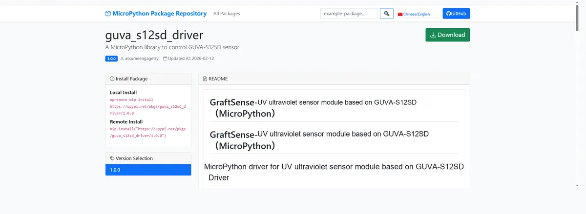
Here, we can use the mip tool to import module driver library code. Below are the usage commands for the mpremote tool:
mpremote mip install github:FreakStudioCN/GraftSense-Drivers-MicroPython/sensors/guva_s12sd_driverImport the UV ultraviolet sensor module based on GUVA-S12SD - MicroPython driver code, then copy the following main.py code into our project:
# MicroPython v1.23.0
# -*- coding: utf-8 -*-
# @Time    : 2025/8/26 10:45 AM
# @Author  : 缪贵成
# @File    : main.py
# @Description : Test file for the UV ultraviolet light matrix module driver. It is recommended not to keep it fully on for long periods. If you need full brightness, replace the resistors, otherwise the board will heat up quickly and cause unexpected consequences

# ======================================== Import Modules =========================================

import time
from uv_matrix import UVMatrix

# ======================================== Global Variables ============================================

# ======================================== Functions ============================================

# ======================================== Custom Classes ============================================

# ======================================== Initialization configuration ===========================================

time.sleep(3)
print("Freak_studio:UV matrix test")
# Initialize UVMatrix, assuming control pin 26 and PWM frequency 1000Hz
uv = UVMatrix(pin=26, pwm_freq=1000)
print("status:", uv.get_state())

# ========================================  Main Program  ===========================================

# Turn on UVMatrix (full brightness)
uv.on()
print("UV is light full:", uv.get_state())
time.sleep(2)

# Half-brightness adjustment
uv.set_brightness(512)
print("UV PWM duty=512")
time.sleep(2)

# Turn off UVMatrix
uv.off()
print("UV status:", uv.get_state())
time.sleep(2)

# Test the toggle state switch
uv.toggle()
print("UV toggle:", uv.get_state())
time.sleep(2)
uv.toggle()
print("UV toggle:", uv.get_state())
Burn the code, open the terminal, and use the mpremote tool to connect to the main controller; the output is as follows:
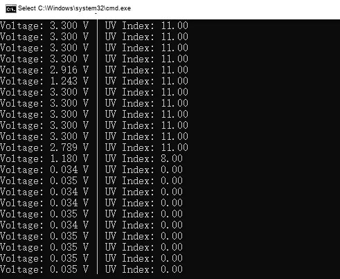
Here we use an ultraviolet lamp to irradiate the module, and it can be seen that UV the value is detected under the change of light intensity and printed on the terminal.
IV. Drivers
guva_s12sd_driver.zip 10 KB
5. BOM & Recommended Alternative Parts
None.
VI. Revision History
Document Version | Date of Revision | Modifier | Modify Content |
v1.0 | 2025.8.13 | Zero Kōkō | Complete the initial version of the design and initialize the document |
v1.1 | 2025.10.24 | Li Zisheng | Added Section 2.8 PCB Routing Notes Revised Section 3, Instructions for Circuit Source Engineering and Module Usage, and added a secondary heading: 3.1 Circuit Source Engineering, 3.2 Module Usage Instructions, 3.3 Application Experiments The BOM sheet has not been finally checked, the driver has not been re-verified, and the 3.3 application experiment Not yet specified. |
v1.2 | 2025-12-29 | Li Zisheng | Added application experiments and production files |
v1.3 | 2025-12-31 | Xin Ruili | Create an open version of the document based on the internal document version v1.2. |
v1.4 | 2026-03-29 | Xin Ruili | Modified the application experiment section |
VII. Relevant Materials
7.1 Chip Datasheet
GUVA-S12SD Datasheet:
GUVA-S12SD.pdf 301 KB
LM358 Datasheet:
lm358.pdf 4.2 MB
7.2 Unique Icons for PCB Silk Screen