Contents
- I. Module Introduction
- II. Introduction to Main Chips
- 2.1 Chip Overview
- 2.2 Pin Definition
- 2.3 Functional Block Diagram
- 2.4 Performance Parameters
- 2.5 Reference Circuit
- 2.6 Chip Configuration
- 2.7 Communication Interfaces and Related Protocols
- 2.8 PCB Routing Notes
- III. Instructions for Circuit Engineering and Module Usage
- 3.1 Circuit Source Engineering
- 3.2 Module Usage Instructions
- 3.3 Application Experiment
- IV. Drivers
- 5. BOM & Recommended Alternative Parts
- VI. Revision History
- VII. Relevant Materials
- 7.1 Chip Datasheet
- 7.2 Unique Icons for PCB Silk Screen
I. Module Introduction
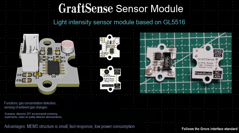
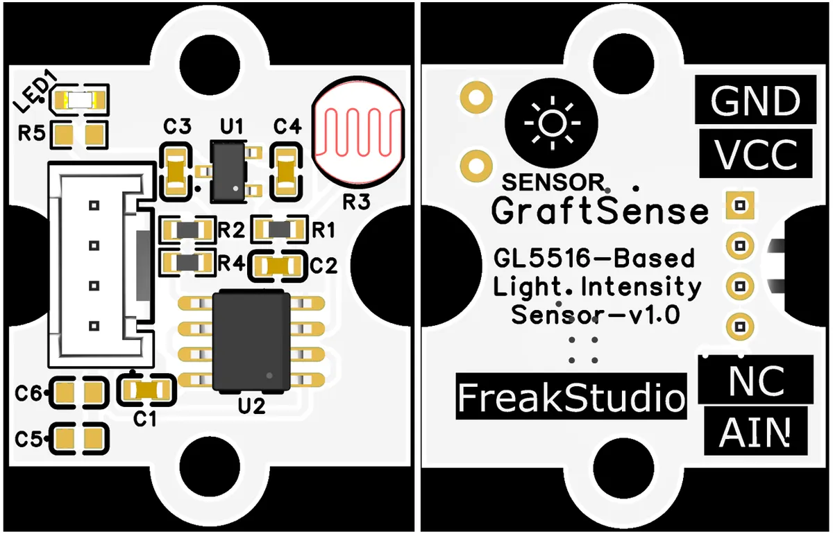
The light intensity sensor module based on GL5516 is a light intensity detection module with GL5516 photoresistor as the core and a voltage follower circuit built with matching LM358 operational amplifier, which outputs analog signals corresponding to the light intensity; in this module, GL5516 features high sensitivity, significant resistance variation with light exposure, and a spectral peak close to human vision, and its operating voltage is compatible with 3.3V-5V systems, adaptable to mainstream microcontrollers such as Arduino and STM32, boasting the characteristics of practical stability and easy debugging.
II. Introduction to Main Chips
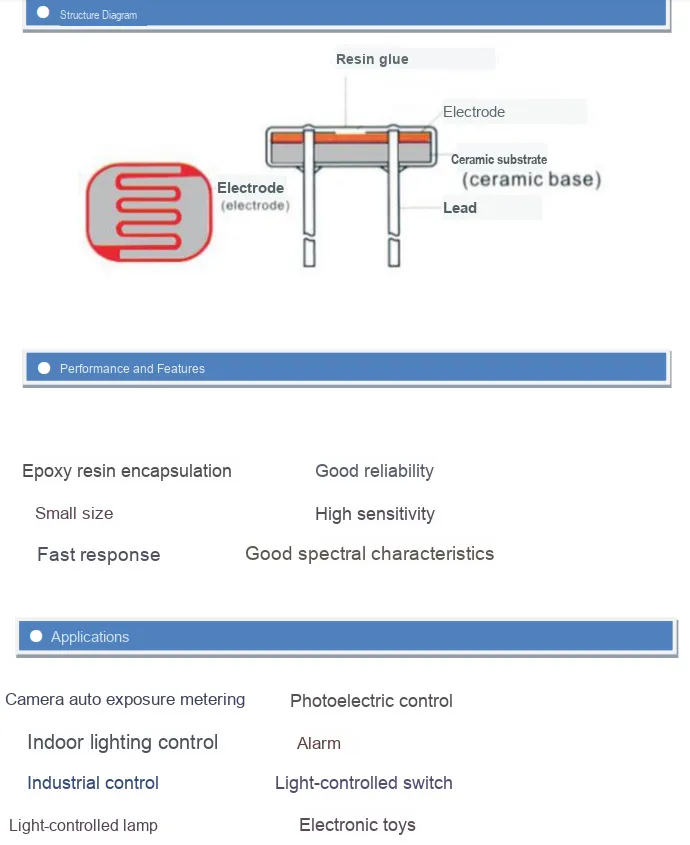
GL5516 is a high-sensitivity photoresistor that responds rapidly to changes in light intensity (with a rise/fall time of 5-10ms), whose resistance varies significantly with illumination (with a light resistance of 5-10kΩ and a dark resistance of up to 0.2MΩ or higher), and whose spectral peak matches the visible light range of the human eye (540-560nm); it is a commonly used optoelectronic device for scenarios such as light intensity detection and ambient light sensing.
2.1 Chip Overview
A photoresistor is a resistor made of semiconductor material, whose electrical conductivity varies with the change of illuminance. By utilizing this characteristic
to fabricate photoresistors with different shapes and light-receiving areas. Photoresistors are widely used in industries such as toys, lamps, and cameras.
2.2 Pin Definition
None.
2.3 Functional Block Diagram
None.
2.4 Performance Parameters
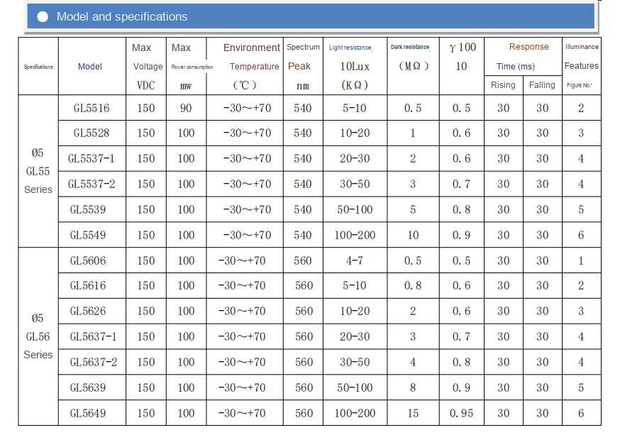
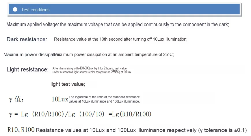
GL5516 is a photosensitive resistor of the GL55 series, with its core parameters and characteristics as follows: it has a maximum operating voltage of 150 VDC, a maximum power dissipation of 90mW, an operating ambient temperature range of -30 to + 70°C, and a spectral response peak at 540nm;In terms of photosensitive performance, the bright resistance under 10Lux (standard light source with a color temperature of 2856K) is 5-10KΩ, and the dark resistance at the 10th second after the 10Lux illumination is turned off is ≥0.5MΩ, the logarithm of the resistance ratio (γ value) under the illuminance of 10Lux and 100Lux is 0.5 (tolerance ±0.1), and the response speeds (rise time and fall time) are both 30ms.These parameters are measured under specific test conditions, reflecting GL5516 's features of low power consumption, fast response and stable photosensitive characteristics, which is suitable for light-load photoelectric induction scenarios such as light intensity detection and light-controlled switches.
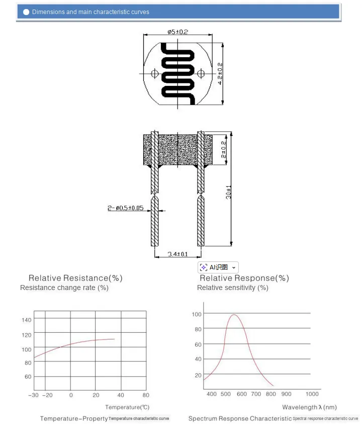
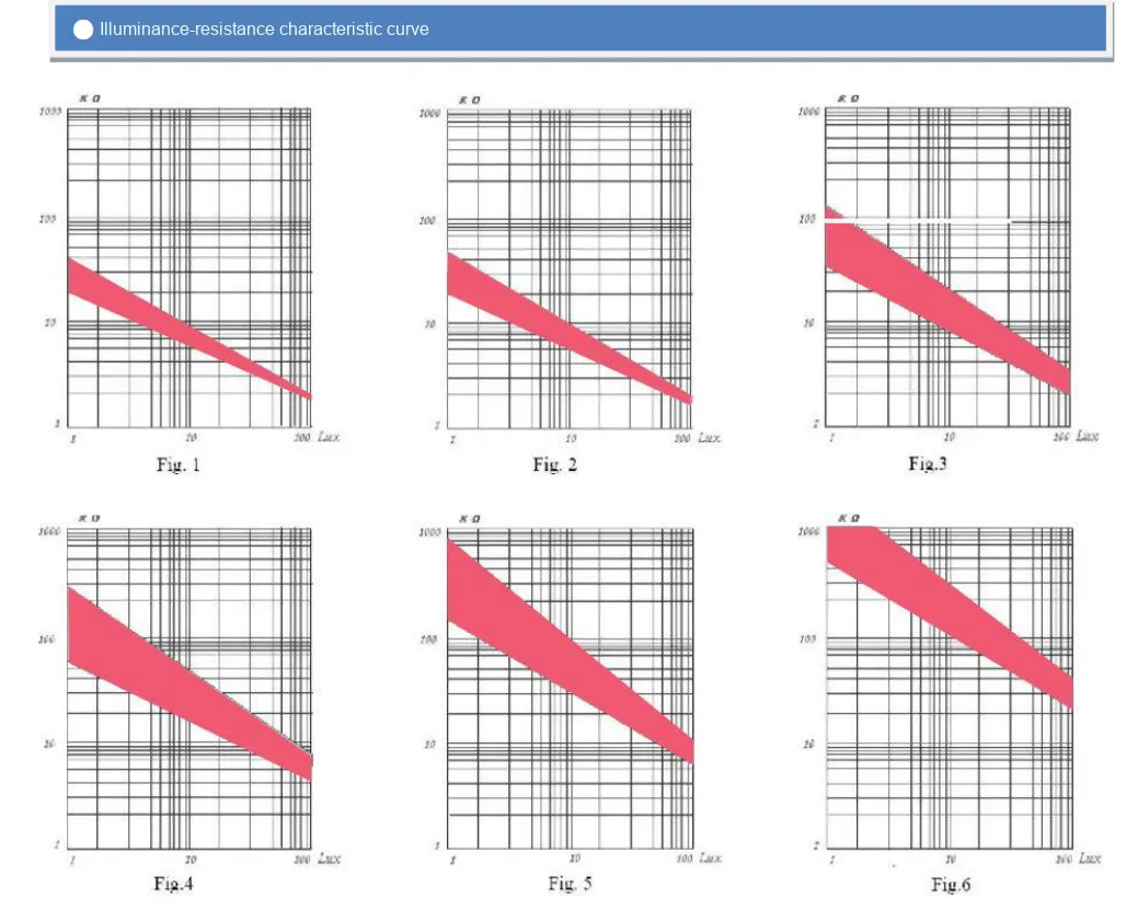
GL5516 Brief description of performance curves: The temperature characteristic curve shows that the resistance change rate rises slowly with increasing temperature, indicating that the impact of temperature on the resistance is relatively mild;the spectral response curve has its peak concentrated around 540nm, which matches its spectral peak parameter and corresponds to the photosensitive response in the visible light region; while the illuminance-resistance characteristic curve intuitively presents a negative correlation of "higher illuminance, lower resistance", and different subgraphs cover the resistance changes in different illuminance ranges, clearly reflecting the light-resistance response law of this photosensitive resistor.
2.5 Reference Circuit
None.
2.6 Chip Configuration
This module is of Plug and Play type, requiring no hardware configuration or software register setup.
2.7 Communication Interfaces and Related Protocols
None.
2.8 PCB Routing Notes
None.
III. Instructions for Circuit Engineering and Module Usage
3.1 Circuit Source Engineering
To obtain the circuit source project, please follow the official account [Freak Embedded]
3.2 Module Usage Instructions
The schematic diagram of this module is shown below:
SCH-GL5516-Based Light Intensity Sensor Module-v1.1_2026-01-28.pdf 2.1 MB
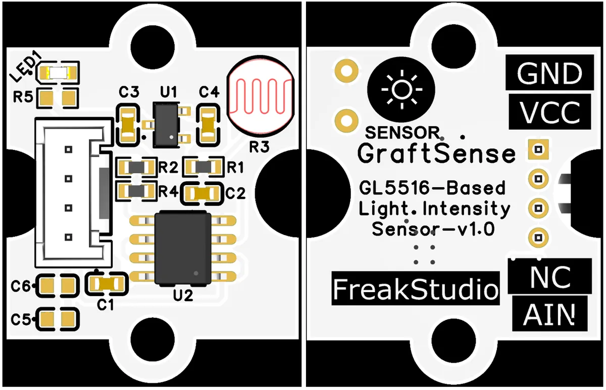
This module provides an AIN analog communication interface: this interface can convert the resistance of the GL5516 photosensitive resistor that varies with light intensity into a corresponding analog voltage signal via the voltage follower circuit constructed by the LM358 operational amplifier. Its output voltage decreases as the light intensity increases, is compatible with 3.3V-5V system voltages, and can be directly connected to the Arduino, STM32 and other mainstream microcontroller ADC interfaces to realize analog quantity acquisition and detection of light intensity.
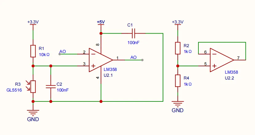
The core function is to detect the light intensity and output analog signals:
- The GL5516 photoresistor (R3) on the left and the 10kΩ resistor R1 form a voltage divider circuit (powered by + 3.3V); when the light intensity changes, the resistance of the GL5516 changes, which will cause the voltage at the voltage divider point to change accordingly;
- The operational amplifier U2.1 (LM358) is configured as a voltage follower (with its output pin 1 connected to the inverting input terminal 2), which functions to buffer the divided voltage signal, and finally outputs the analog quantity AO (the voltage signal corresponding to light intensity) from pin 1; C1 (100nF) is used to stabilize the output of the operational amplifier.
3.3 Application Experiment
Here, we use the GraftPort-RP2040 development board for testing, and connect the GL5516-based light intensity sensor module to the main controller via the AIN interface.
Here, we first use the HY2.0-4P connection cable to connect the module to the GraftPort-RP2040 development board's AIN0 interface:
The module connections are shown in the following table:
Development Board Pins | Module Pins | Description |
Pin 26 |
| - |
Pin 19 |
| - |
Here, we need to search for the relevant driver packages on uPyPI: https://upypi.net/zh/
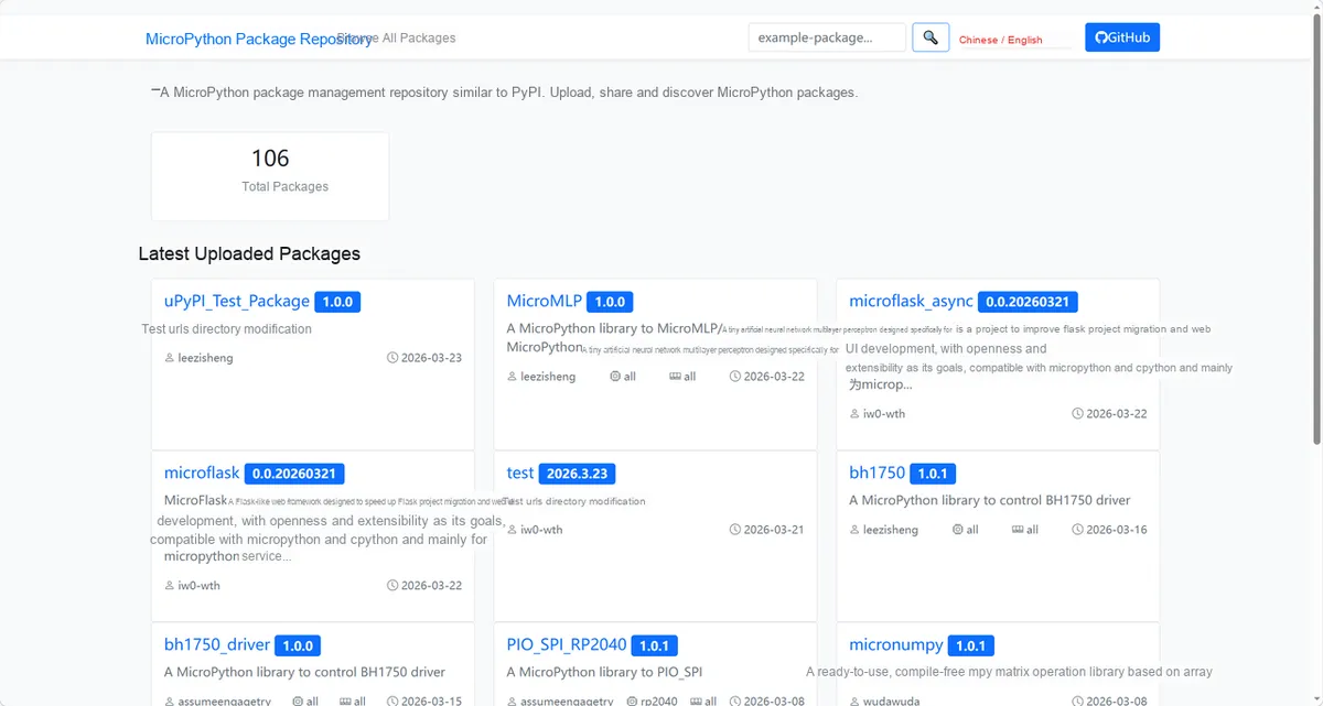
Enter gl5516_driver to search, and the following will be displayed:

Click to copy the local installation command:
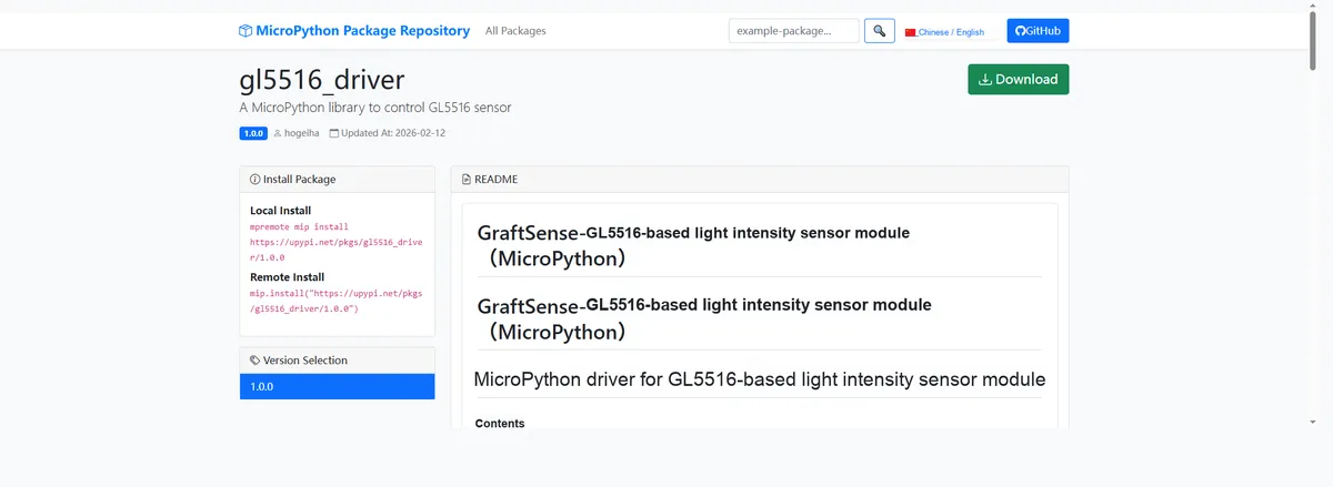
Here, we can import the module driver library code via the mip tool, and the following are the usage commands for the mpremote tool:
mpremote mip install github:FreakStudioCN/GraftSense-Drivers-MicroPython/sensors/gl5516_driverImport the light intensity sensor module based on GL5516 - MicroPython driver code, then copy the following main.py code into our project:
# Python env   : MicroPython v1.23.0
# -*- coding: utf-8 -*-
# @Time    : 2025/8/22 PM 12:49
# @Author  : hogeiha
# @File    : main.py
# @Description : Test file for the GL5516-based light intensity sensor module

# ======================================== Import Modules =========================================

from gl5516 import GL5516
import time

# ======================================== Global Variables =============================================

# ======================================== Functions =============================================

# ======================================== Custom Classes =============================================

# ======================================== Initialization configuration ===========================================

# Initialize the GL5516 light intensity sensor, connected to pin GPIO26
adc = GL5516(26)

# Calibrate the light intensity sensor
# Interactive user calibration: set the minimum value in the darkest lighting and the maximum value in the brightest lighting
# Set the minimum value
input("Place sensor in LOW light environment and press Enter to set minimum light...")
adc.set_min_light()
print(f'min_light:{adc.min_light}')
time.sleep(1)

# Set the maximum value
input("Place sensor in HIGH light environment and press Enter to set minimum light...")
adc.set_max_light()
print(f'max_light:{adc.max_light}')
time.sleep(1)

# ======================================== Main Program ===============================================

while True:
    # Read the light intensity data
    voltage, adc_value = adc.read_light_intensity()
    print("Light Intensity - Voltage: {} V, ADC Value: {}".format(voltage, adc_value))
    # Get the calibrated light intensity percentage
    light_level = adc.get_calibrated_light()
    print("Calibrated Light Level: {:.2f}%".format(light_level))
    time.sleep(2)
When flashing the code, the terminal output goes through the following three stages:
Light Intensity Level Calibration:

Place the sensor in a low-light environment, then press the Enter key to set the minimum light intensity threshold;
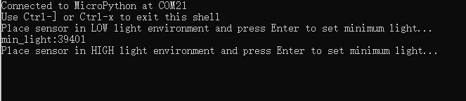
Place the device in a strong light environment and press the Enter key to set the maximum light intensity threshold
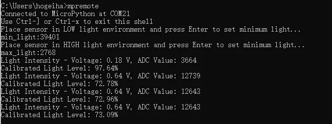
After calibration is completed, the voltage corresponding to the real-time output light intensity, the ADC value, and the calibrated light intensity level will be output.
IV. Drivers
gl5516_driver.zip 4 KB
5. BOM & Recommended Alternative Parts
None.
VI. Revision History
Document Version | Date of Revision | Modifier | Modify Content |
v1.0 | 2025-12-25 | Zero Kōkō | Initialize the document |
v1.1 | 2025-12-29 | Li Zisheng | Added application experiments and production files |
v1.2 | 2026-02-03 | Li Zisheng | Changed the original power supply of the operational amplifier to + 5V |
v1.3 | 2026-02-03 | Xin Ruili | Create an open version of the document based on the internal document version v1.2. |
v1.4 | 2026-03-29 | Xin Ruili | Modified the application experiment section |
VII. Relevant Materials
7.1 Chip Datasheet
GL5516 Datasheet.pdf 409 KB
7.2 Unique Icons for PCB Silk Screen