Contents
- I. Module Introduction
- II. Introduction to Main Chips
- 2.1 Chip Overview
- 2.2 Pin Definition
- 2.3 Functional Block Diagram
- 2.4 Performance Parameters
- 2.5 Reference Circuit
- 2.6 Chip Configuration
- 2.7 Communication Interfaces and Related Protocols
- 2.8 PCB Routing Notes
- III. Instructions for Circuit Engineering and Module Usage
- 3.1 Circuit Source Engineering
- 3.2 Module Usage Instructions
- 3.3 Application Experiment
- IV. Drivers
- 5. BOM & Recommended Alternative Parts
- VI. Revision History
- VII. Relevant Materials
- 7.1 Chip Datasheet
- 7.2 Unique Icons for PCB Silk Screen
I. Module Introduction
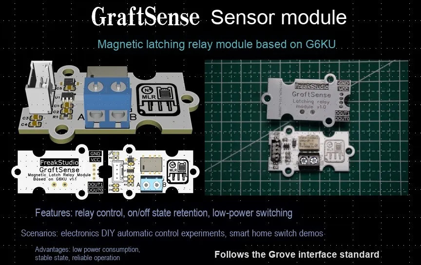
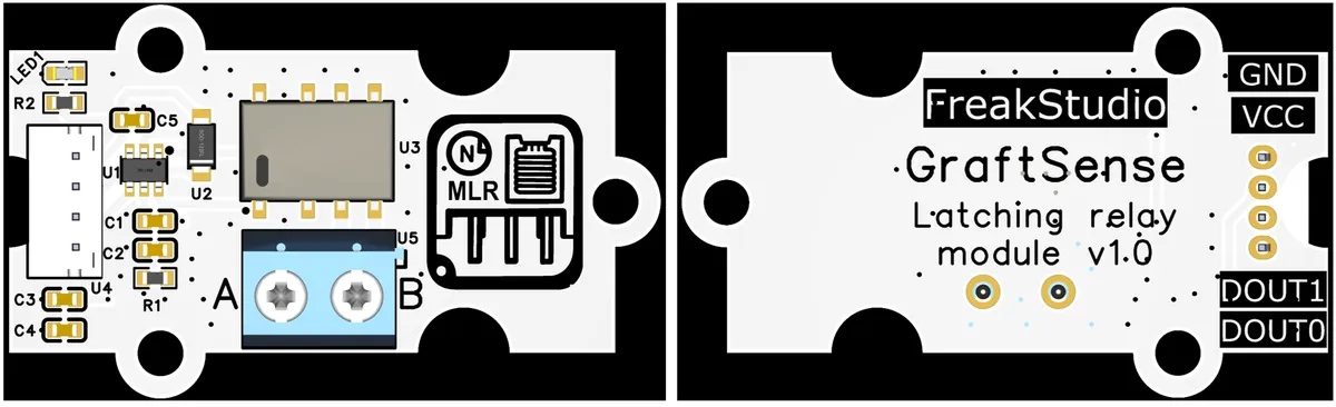
G6KU-based latching relay module takes the G6KU ultra-compact SMD latching relay as the core, and is designed with the FM116C H-bridge driver IC: it drives the latching relay via an H-bridge circuit, and is equipped with a diode freewheeling circuit to ensure circuit stability; the latching feature enables the module to achieve extremely low power consumption, while the G6KU relay itself boasts advantages such as ultra-small size (suitable for high-density layout) and high dielectric strength, and the module can carry a load of 125V 0.3A AC or 30V 1A DC.When in use, connect the control terminal to the GND, VCC, DOUT1, and DOUTO interfaces on the right side of the module, then connect the external load to the A and B output terminals to complete the connection.
II. Introduction to Main Chips
This module mainly uses G6KU ultra-compact SMD latching relays and FM116C H-bridge driver IC.
2.1 Chip Overview
2.1.1 G6KU Latching Relay
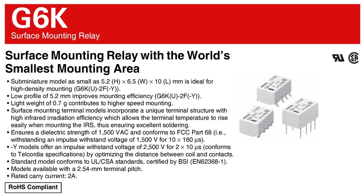
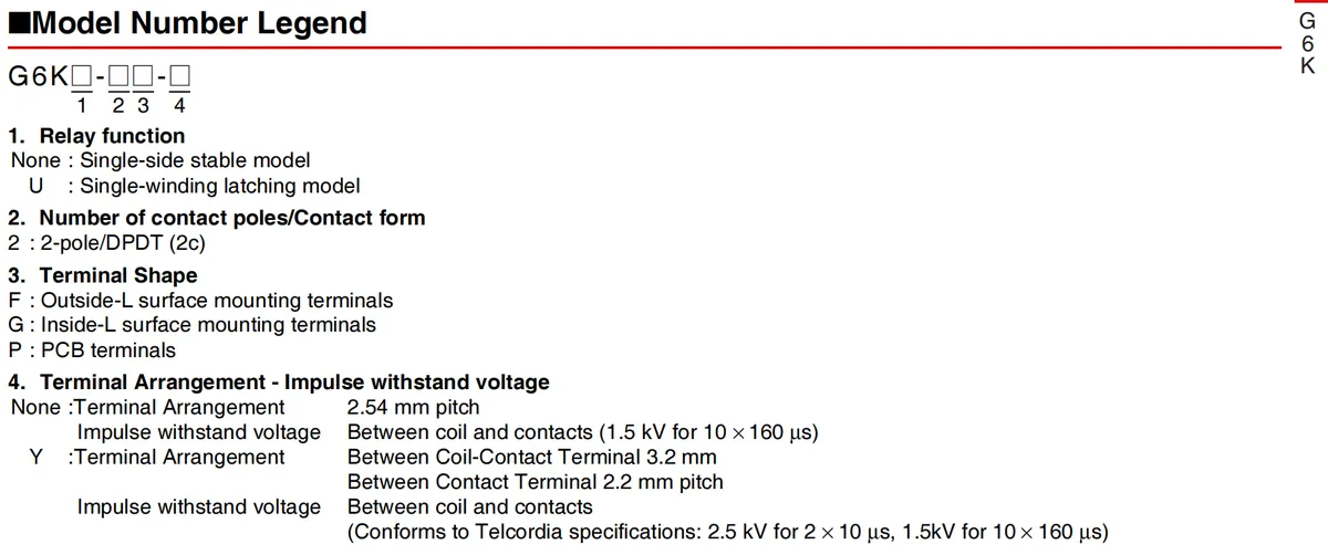
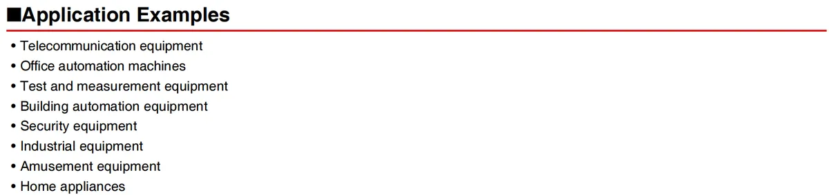
G6K is a surface-mount relay featuring the "world's smallest installation footprint" as its core selling point, with a key advantage of an ultra-compact design: it measures merely 5.2 (H) × 6.5 (W) × 10 (L) mm, has a thickness of 5.2 mm and weighs only 0.7 g, making it suitable for high-density circuit layouts; its surface-mount terminals adopt a unique structure, delivering high infrared soldering efficiency and excellent soldering stability.
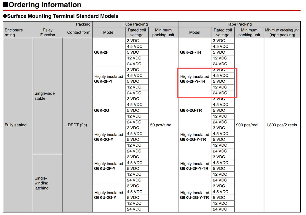
Its model numbers use codes to distinguish functions (e. g., in G6K (U)-2F (Y))), where U denotes single-winding magnetically latching type, 2 indicates 2-pole DPDT contacts, F stands for outer-side L type SMT terminals, and Y refers to the high pulse withstand voltage version with optimized terminal layout). In terms of performance, it features a dielectric strength of 1500VAC (the Y type offers a pulse withstand voltage of 2500V), a rated current-carrying capacity of 2A, and complies with certifications including UL / CSA as well as the RoHS standard.
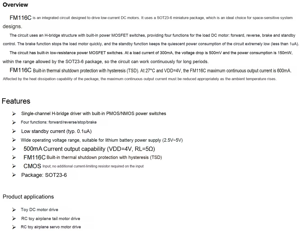
2.1.2 FM116C Motor Driver Chip
2.2 Pin Definition
2.2.1 G6KU Latching Relay
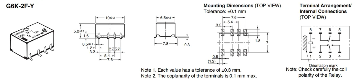
G6K-2F-Y relay (top view) has a total of 8 pins: pins 1 and 2 are coil pins; pins 3-8 are 2-pole double-throw (DPDT) contact pins, corresponding to the normally open / normally closed contacts of the two channels, for connecting to an external load circuit.
When in use, distinguish between coil pins and contact pins, and meanwhile pay attention to the polarity matching of the coil.
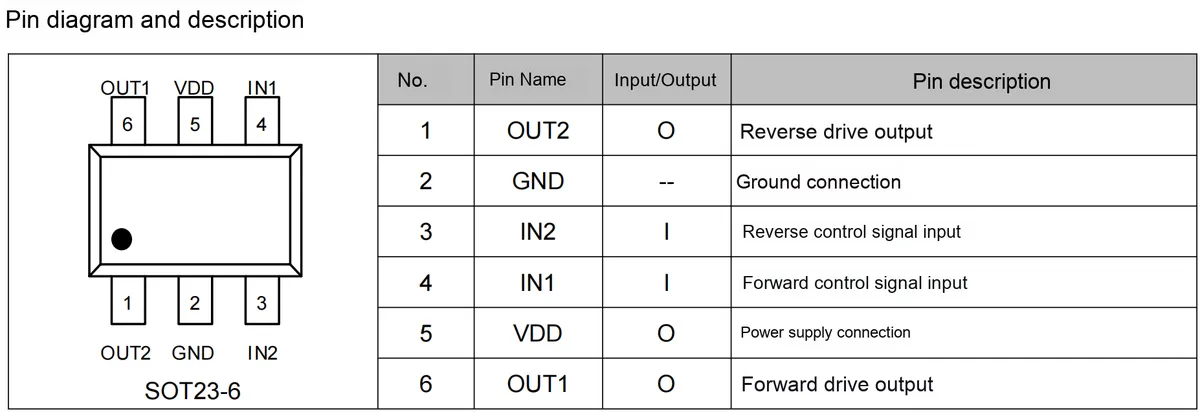
2.2.2 FM116C Motor Driver Chip
2.3 Functional Block Diagram
2.3.1 G6KU Latching Relay
None.
2.3.2 FM116C Motor Driver Chip
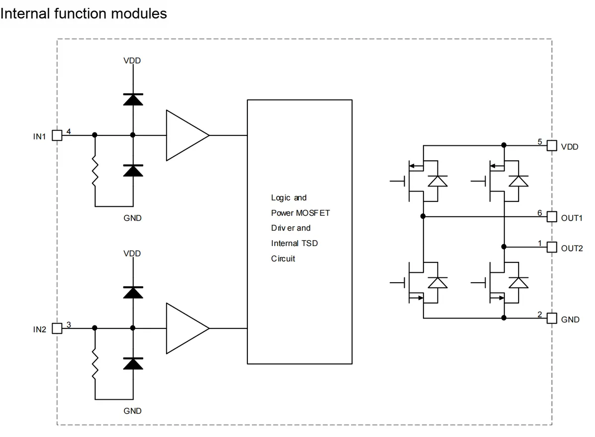
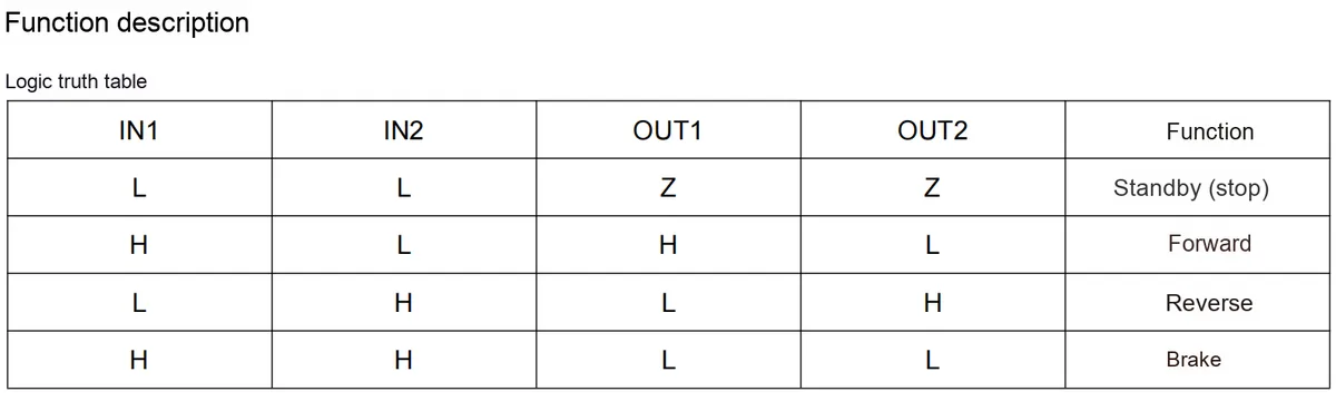
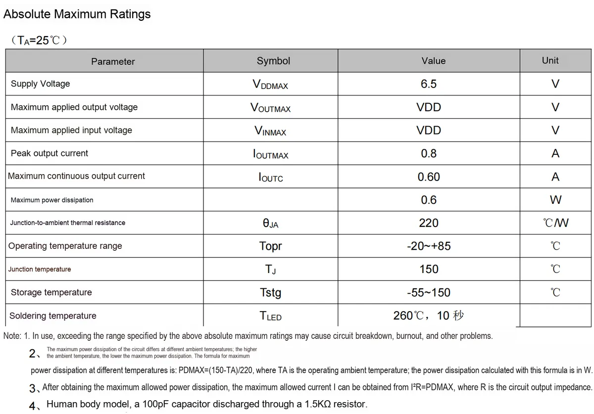
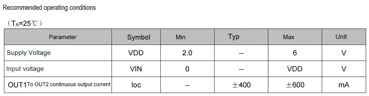
On the left is the input processing unit (corresponding to the IN1 / IN2 pins), and each input is equipped with a pull-down resistor, an ESD protection diode and a buffer to stabilize the input signal and protect against electrostatic interference; in the middle is the core module, which integrates logic control and power MOSFET drive circuits, and also includes an internal thermal shutdown (TSD) circuit, responsible for signal processing, drive control and over-temperature protection;On the right is the H-bridge power output unit (corresponding to the VDD / OUT1 / OUT2 / GND pins), which consists of MOS transistors with freewheeling diodes and can implement driving functions such as forward/reverse rotation and braking for the load.
2.4 Performance Parameters
2.4.1 G6KU Latching Relay
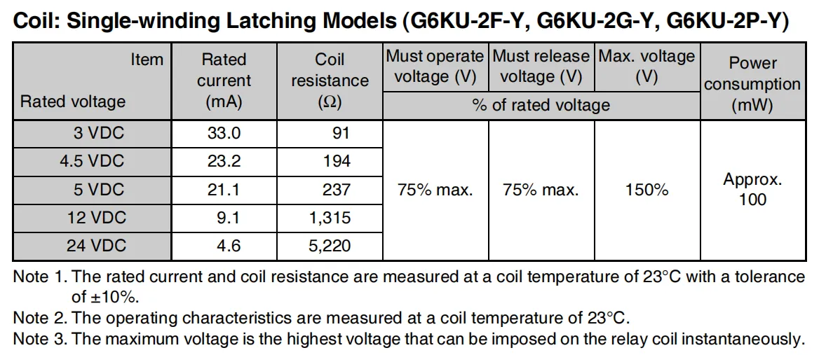
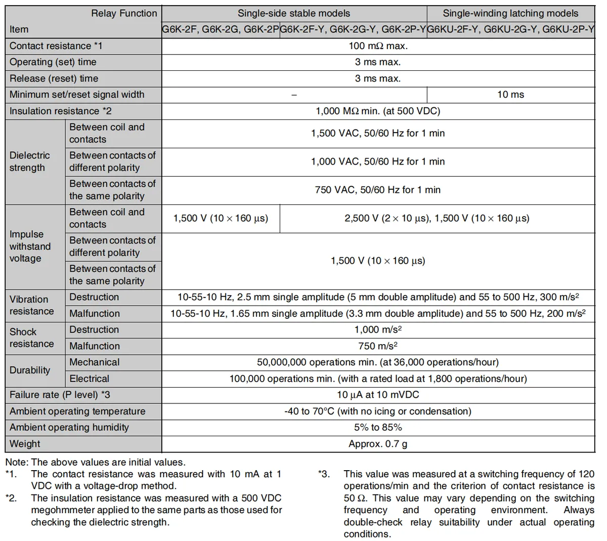
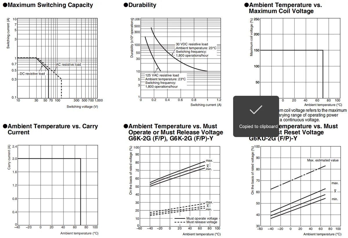
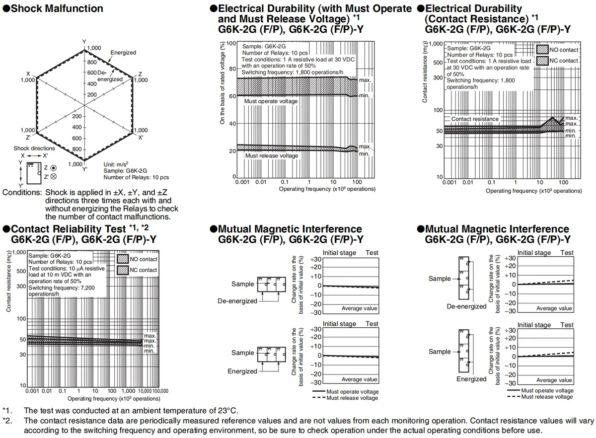
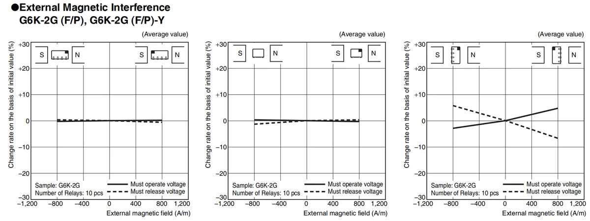
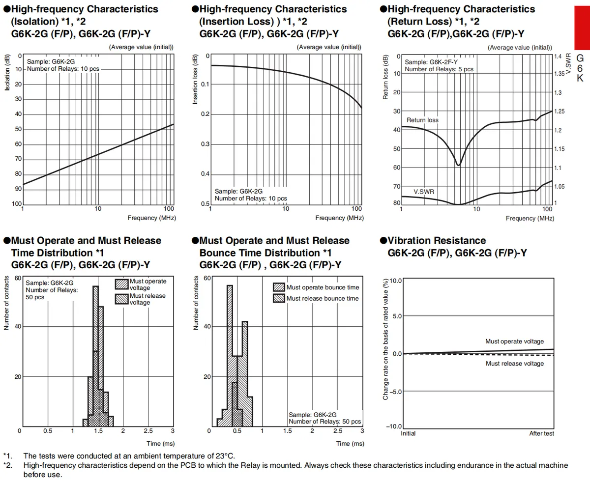
G6K-2F-Y is a fully sealed, single-side stable 2-pole double-throw (DPDT) high-insulation patch relay, with its core parameters as follows: the coil supports rated voltages such as 3/4.5/5/12/24VDC (taking 3VDC as an example, the rated current is 33mA and the coil resistance is 91Ω), the operate/release voltage does not exceed 75% of the rated value, the maximum instantaneous voltage is 150% of the rated value, and the power consumption is about 100mW;In terms of performance, it features a maximum contact resistance of 100mΩ, an operating time ≤3ms, a release time ≤100ms, an insulation resistance between the coil and contacts ≥1000MΩ(500VDC), a dielectric strength of 1500VAC (coil to contacts), a mechanical lifespan of no less than 50 million cycles, an electrical lifespan of no less than 100,000 cycles, an operating temperature and humidity range of -40~70℃ and 5%-85%, and a weight of approximately 0.7g.
2.4.2 FM116C Motor Driver Chip
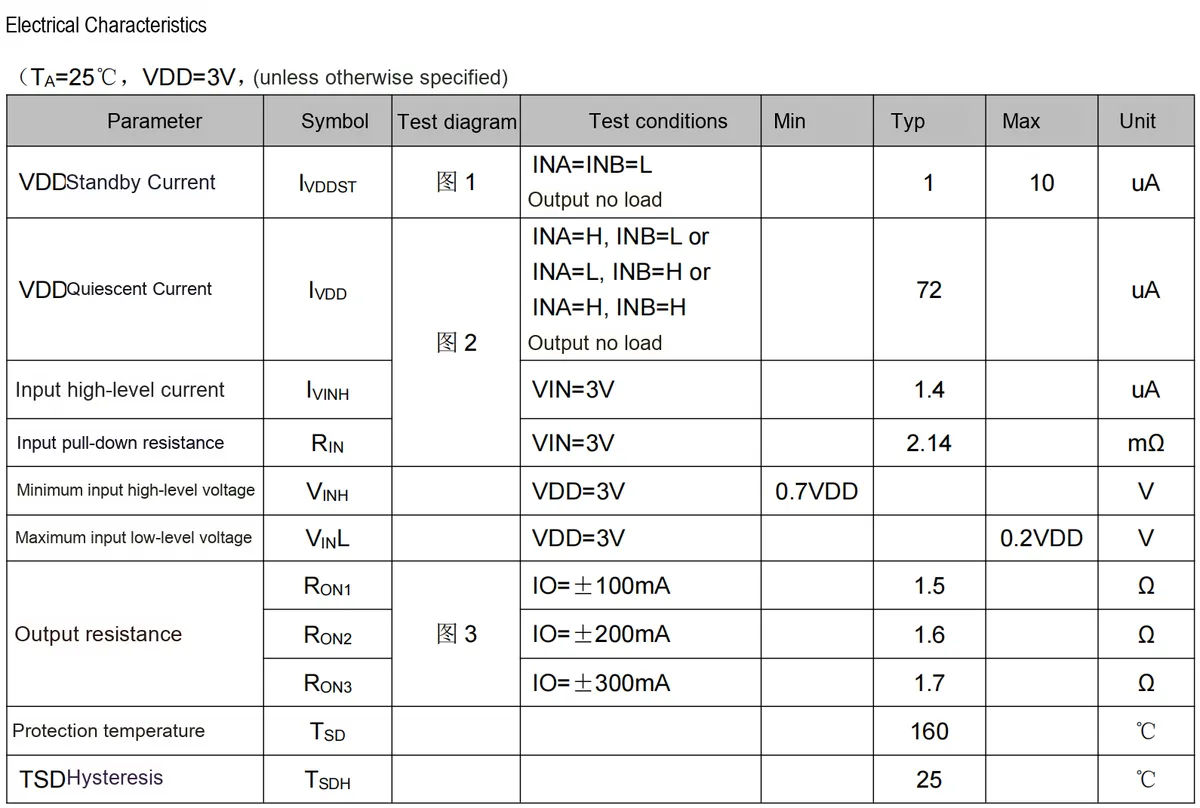
2.5 Reference Circuit
2.5.1 G6KU Latching Relay
None.
2.5.2 FM116C Motor Driver Chip
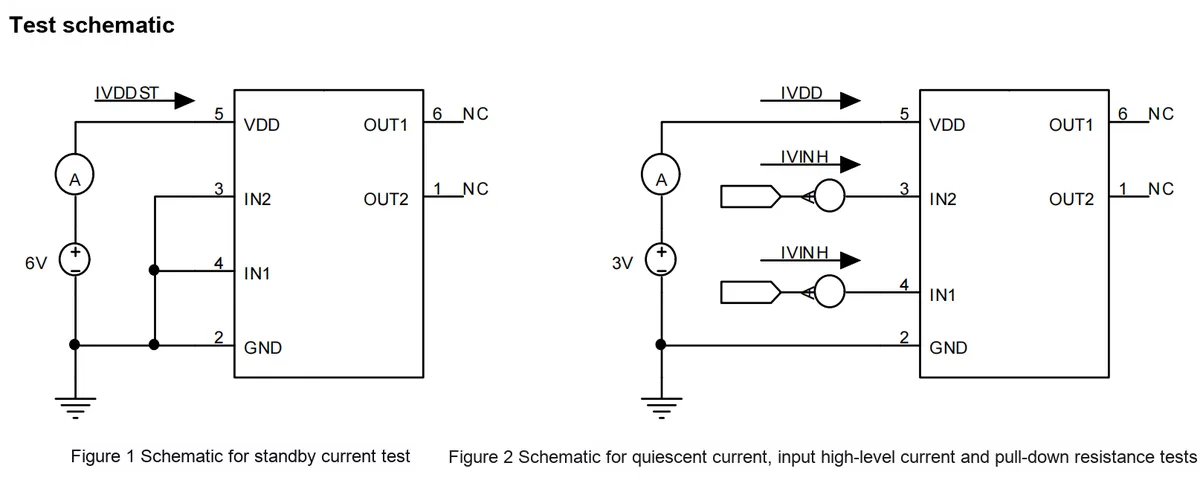
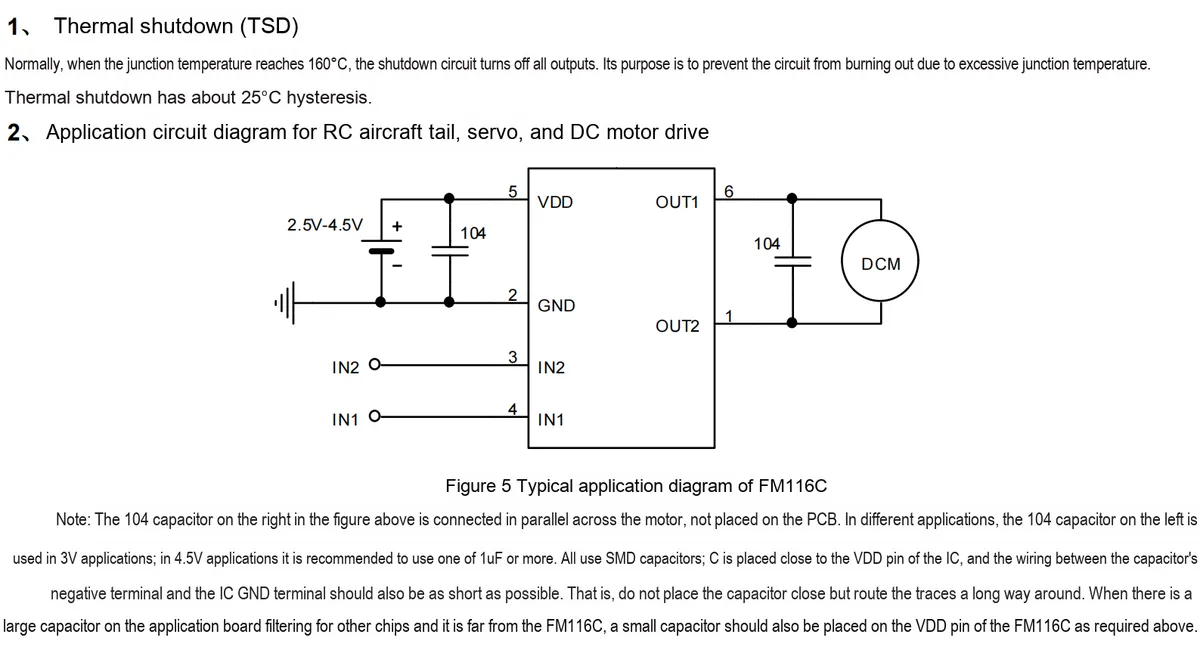
Figure 1 shows the standby current test, which is conducted by connecting a 6V power supply to VDD / GND, shorting IN1 / IN2 to GND, and measuring the current during standby with an ammeter; Figure 2 is used for static current, input high-level current and pull-down resistance testing, where measurement is performed by inputting a high-level signal to IN1/IN2 under a 3V power supply.
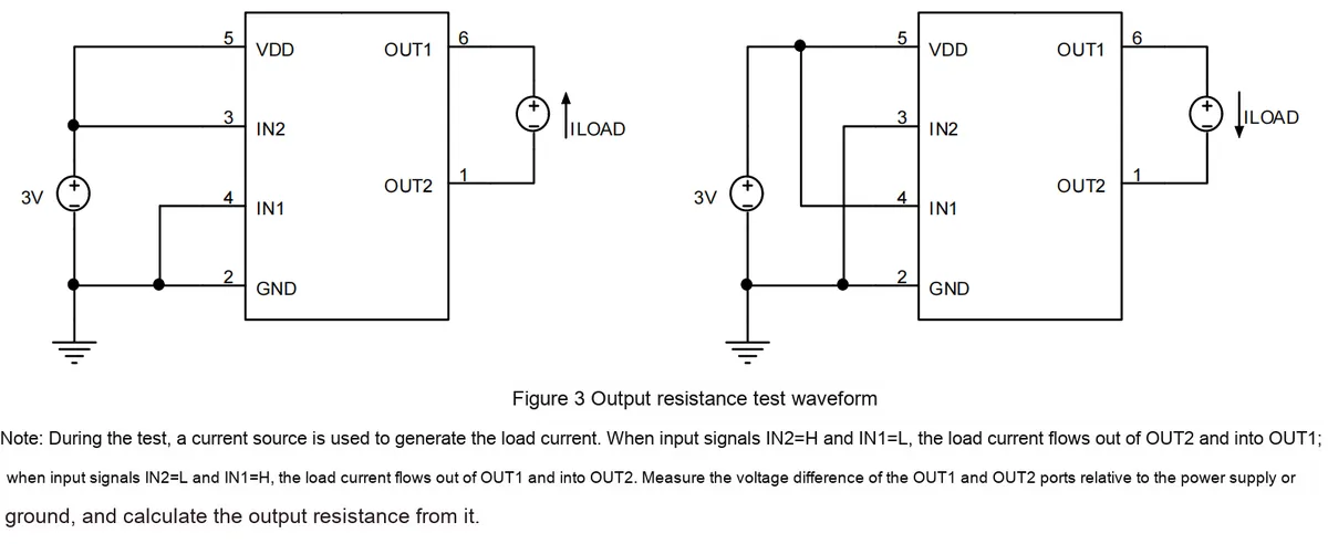
Figure 3 shows the output resistance test, where a current source is used to apply a load to OUT1 / OUT2, the direction of the load current is changed by switching the high and low levels of IN1 / IN2, and the output resistance is calculated by measuring the port voltage difference.
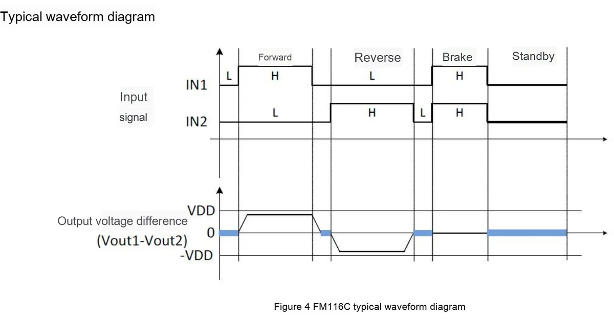
Figure 4 shows the typical operating waveforms, which illustrate the variation logic of the output voltage difference between IN1 / IN2 in different level combinations corresponding to forward rotation, reverse rotation, braking and standby modes, and OUT1 and OUT2.
2.6 Chip Configuration
2.6.1 G6KU Latching Relay
None.
2.6.2 FM116C Motor Driver Chip
None.
2.7 Communication Interfaces and Related Protocols
2.7.1 G6KU Latching Relay
None.
2.7.2 FM116C Motor Driver Chip
None.
2.8 PCB Routing Notes
2.8.1 G6KU Latching Relay
None.
2.8.2 FM116C Motor Driver Chip
PCB routing considerations for FM116C are as follows:
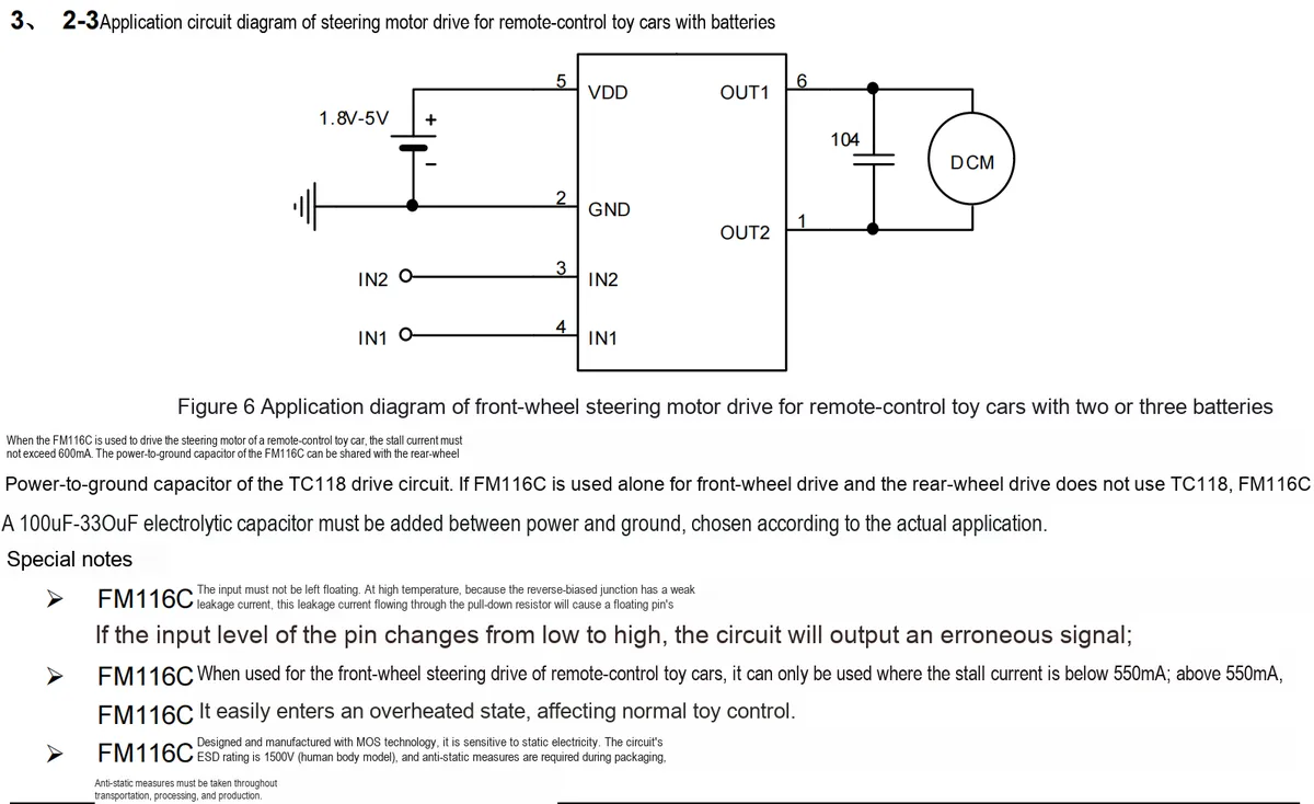
VDDPin Filter Capacitor Layout: The surface-mount filter capacitor (e. g. 104 capacitor) of theVDDpin shall be placed close to theFM116C'sVDDpin; in addition, the connection between the negative terminal of the capacitor and theIC' sGNDpin shall be as short as possible, avoid long routing, so as to ensure the filtering effect;- Additional filter capacitor: If there is already a large capacitor on the PCB for filtering other chips but it is far from
FM116C, an additional small filter capacitor shall be added at theFM116CVDDpin; - Power Capacitor Layout (Toy Car Drive Scenario): If used alone
FM116Cfor steering drive of remote-controlled toy cars, the electrolytic capacitor (100μF-330μF) at its power terminal should also be laid out close to the corresponding pin to improve power supply stability.
III. Instructions for Circuit Engineering and Module Usage
3.1 Circuit Source Engineering
To obtain the circuit source project, please follow the official account [Freak Embedded]
3.2 Module Usage Instructions
The principle of this module is shown as follows:
SCH_G6KU-Based_Magnetic_Latching_Relay_Module_v1.0_2025-11-26.pdf 2.6 MB
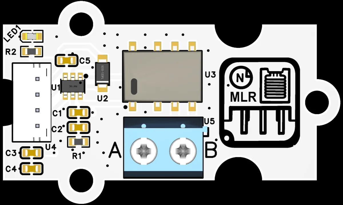
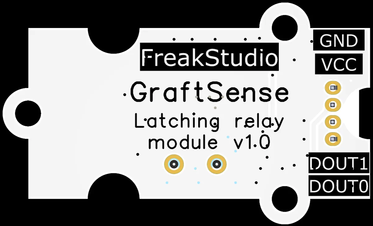
This module provides two digital interfaces DOUT0 and DOUT1 (corresponding to DOUT1 and DOUT2 in the schematic): in combination with the logic truth table and the H-bridge driving principle:
- When the control signal sets
DOUT1to a high level andDOUT0to a low level (corresponding to the condition ofIN1= H, IN2= Lin the truth table), the H-bridge outputs a forward pulse voltage to drive the latching relay to complete the turn-on (pull-in) operation; - When the control signal sets
DOUT1to a low level andDOUT0to a high level (corresponding to the condition ofIN1= L, IN2= Hin the truth table), the H-bridge outputs a reverse pulse voltage to drive the latching relay to complete the closing (release) operation.
Due to the characteristics of the latching relay, after the pull-in/closure is completed, even if the interface returns to the standby (IN1= IN2= L) or braking (IN1= IN2= H) state, the relay will maintain the current on/off state without continuous power supply.
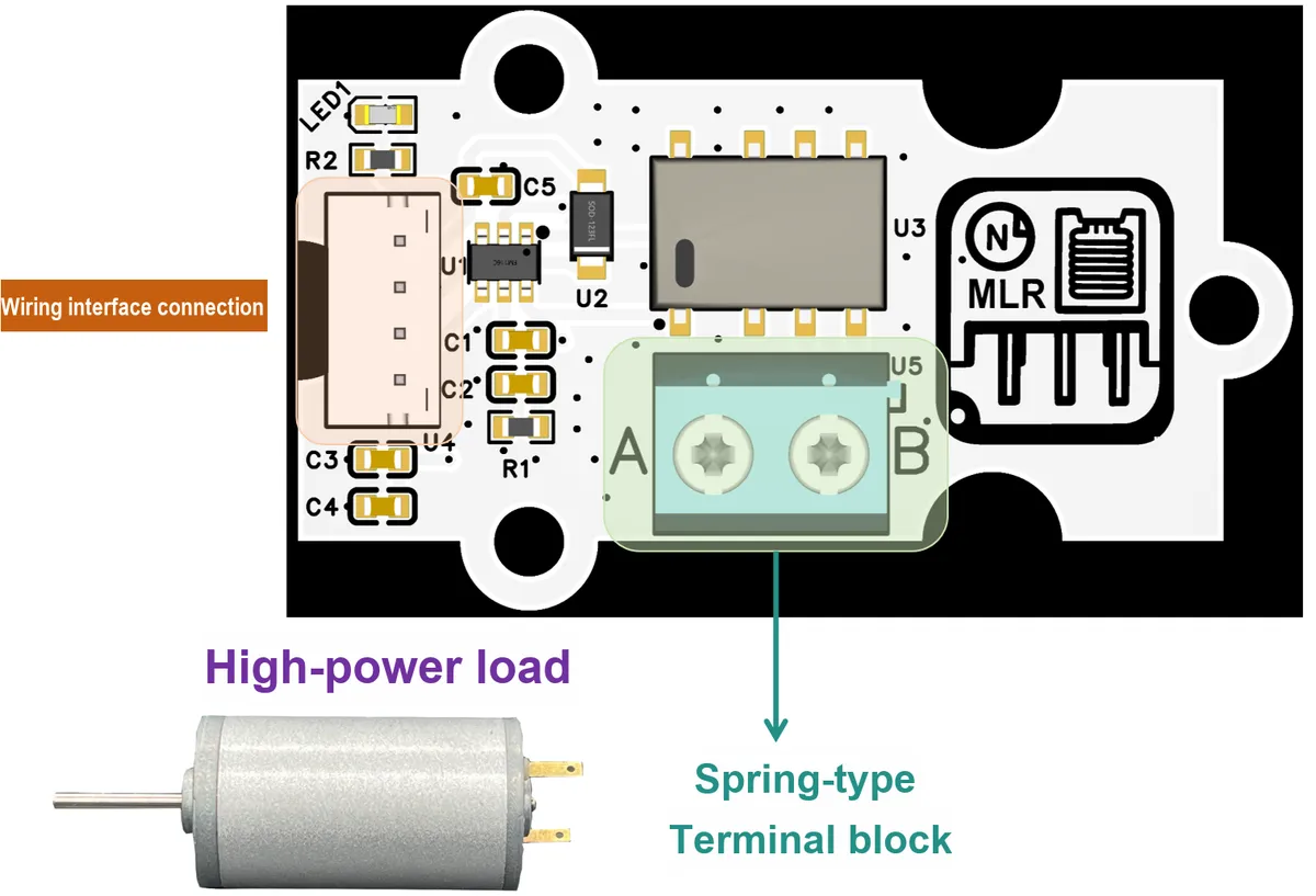
When in use, we can make the connection in the following way:
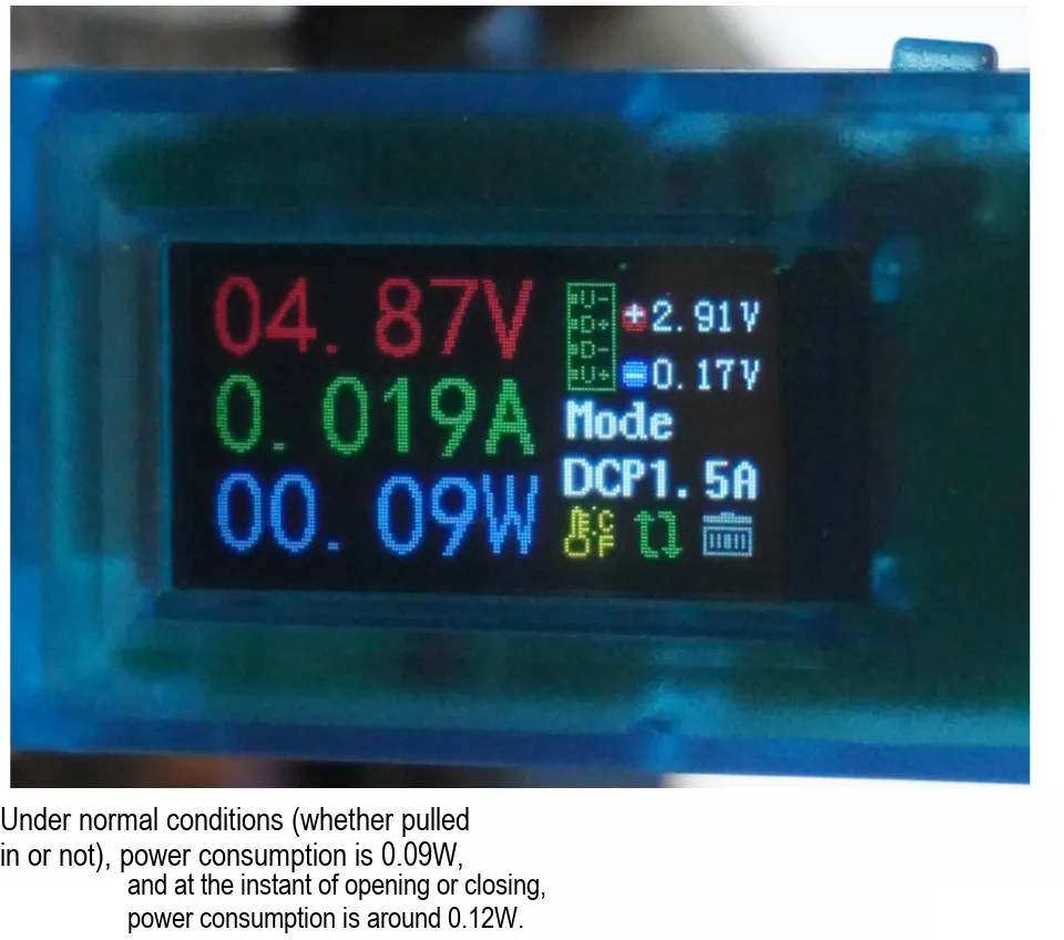
Meanwhile, we have also conducted tests on its power consumption:
3.3 Application Experiment
Here, we use the GraftPort-RP2040 development board for testing, and the G6KU-based latching relay module uses the DIO interface to communicate with the main controller.
Here, we first use the HY2.0-4P connection cable to connect the module to the GraftPort-RP2040 development board's DIO1 interface:
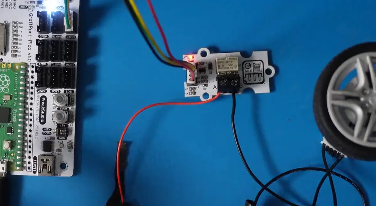
The module connections are shown in the following table:
Development Board Pins | Module Pins | Description |
Pin 14 |
| The pins connected to the MCU output high and low levels. |
Pin 15 |
| - |
- Power supply output
5Vvoltage, which is divided into two lines: positive pole andGND(negative pole). - The positive terminal of the power supply is connected to node
A, serving as the positive input terminal of the power supply backbone. - The positive terminal of the motor (Motor +) is not directly connected to the power supply, but is connected to the output terminal of the relay.
- Power supply
GNDis directly connected to the negative terminal of the motor (motor -) to form the foundation of the circuit.
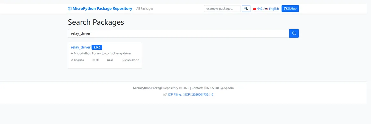
Here, we need to search for the relevant driver packages on uPyPI: https://upypi.net/zh/
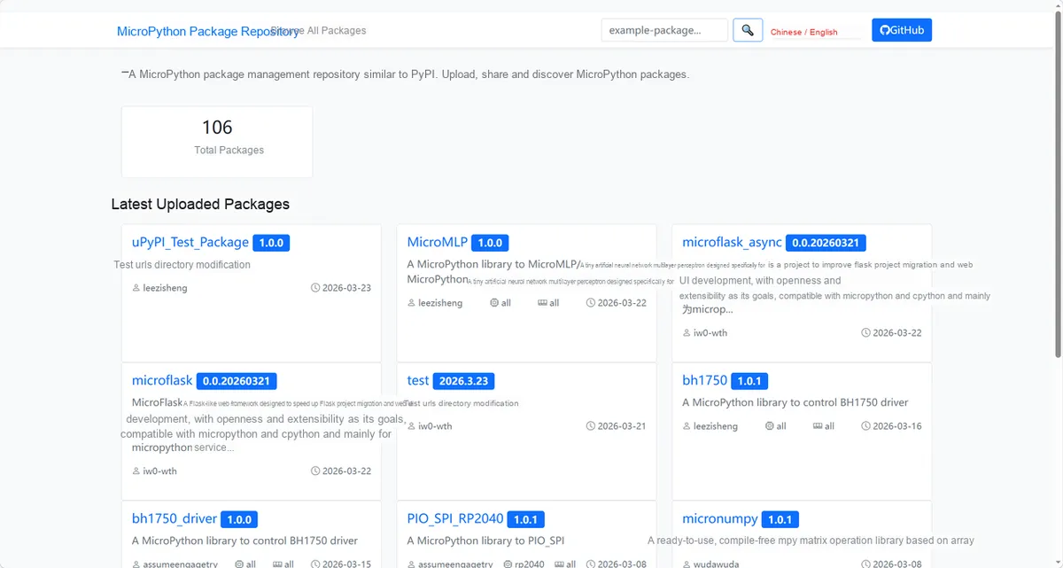
Enter relay_driver to search, and the following will be displayed:
Click to copy the local installation command:
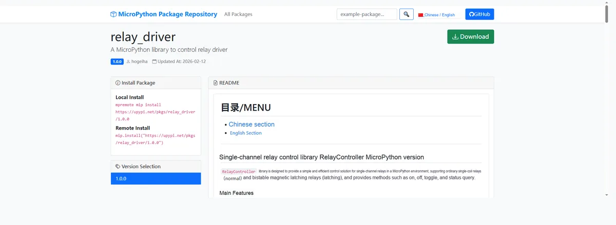
Import the module driver library code via the mip tool. Below are the usage commands for the mpremote tool:
mpremote mip install https://upypi.net/pkgs/relay_driver/1.0.0After importing the relay module driver - MicroPython driver code, copy the following main.py code into our project:
# Python env   : MicroPython v1.23.0
# -*- coding: utf-8 -*-
# @Time    : 2024/7/28 3:00 PM
# @Author  : Li Qingshui
# @File    : main.py
# @Description : Relay test example

# ======================================== Import Modules ========================================

# Import time-related modules
import time
# Import the relay module
from relay import RelayController

# ======================================== Global Variables ============================================

# If it is a 'normal' type relay, use GP14
RELAY_TYPE = 'normal'   # 'normal' or 'latching'
RELAY_PIN1 = 14           # Control pin 1
RELAY_PIN2 = 15           # Control pin 2

# Music rhythm definition (unit: ms)
# Each tuple represents (duration, whether to toggle at the end)
MUSIC_NOTES = [
    # Strong rhythm in the intro
    (50, True), (50, False), (50, True), (50, False),  # 4 fast consecutive beats
    (100, True), (100, False),  # Slow down for 2 beats
    (50, True), (50, False), (50, True), (50, False),  # Repeat 4 fast beats

    # Verse section
    (150, True), (50, True), (200, False),  # Strong-light-long pause
    (100, True), (100, True), (100, True), (100, False),  # Three consecutive hits
    (80, True), (80, True), (160, False),  # Double beat + long pause
    (60, True), (60, True), (60, True), (60, True), (120, False),  # Four fast consecutive hits

    # Chorus climax
    (40, True), (40, False), (40, True), (40, False),  # Ultra-fast eighth notes
    (40, True), (40, False), (40, True), (40, False),
    (200, True), (200, False),  # Strong downbeat
    (300, True), (100, True), (200, False),  # Long-short combination

    # Bridge tempo change
    (120, True), (80, True), (120, True), (80, False),
    (200, True), (50, True), (50, True), (200, False),

    # Ending slows down gradually
    (150, True), (150, False),
    (200, True), (200, False),
    (300, True), (300, False)
]
# ======================================== Functions ============================================

# Simple music playback function
def play_relay_music():
    for duration, should_toggle in MUSIC_NOTES:
        # Toggle the relay state
        relay.toggle()
        time.sleep_ms(duration)
        if should_toggle:
            # Toggle back again
            relay.toggle()
            # Add a small interval to prevent toggling too fast
            time.sleep_ms(50)

# ======================================== Custom Classes ============================================

# ======================================== Initialization ==========================================

# Power-on delay of 3 s
time.sleep(3)
# Print debug information
print("FreakStudio: Using GraftPort to control relay")

# Initialize the relay controller
if RELAY_TYPE == 'latching':
    relay = RelayController(RELAY_TYPE, RELAY_PIN1, RELAY_PIN2)
else:
    relay = RelayController(RELAY_TYPE, RELAY_PIN1)

# ========================================  Main Program  ===========================================

# Turn on the relay
relay.on()
print('relay.on')
# Delay 1s
time.sleep(5)
# Turn off the relay
relay.off()
print('relay.off')
Burn the code, open a terminal, and use the mpremote tool to connect to the main controller; the output is as follows:

We can hear that the relays close and release in a certain regular pattern, just like music.
It can be observed that when the relay is closed, the motor starts to rotate; after 5 seconds, the relay opens and the motor stops.
IV. Drivers
relay_driver.zip 11 KB
5. BOM & Recommended Alternative Parts
None.
VI. Revision History
Document Version | Date of Revision | Modifier | Modify Content |
v1.0 | 2025-11-26 | Li Zisheng | Initialize the document The BOM sheet has not been finally checked, the driver has not been re-verified, and the 3.3 application experiment Not yet specified. |
v1.1 | 2025-12-29 | Li Zisheng | Added application experiments and production files |
v1.2 | 2025-12-31 | Xin Ruili | Create an open version of the document based on the internal document version v1.1. |
v1.3 | 2026-03-29 | Xin Ruili | Modified the application experiment section |
VII. Relevant Materials
7.1 Chip Datasheet
C2153173_Magnetic Latching Relay_G6KU-2F-Y-TR+DC5_Datasheet_WJ323416.PDF 1.8 MB
C2802264_Brushed DC Motor Driver Chip_FM116C_Datasheet_WJ68220.PDF 346 KB
7.2 Unique Icons for PCB Silk Screen