Contents
- I. Module Introduction
- II. Introduction to Main Chips
- 2.1 Chip Overview
- 2.2 Pin Definition
- 2.3 Functional Block Diagram
- 2.4 Performance Parameters
- 2.5 Reference Circuit
- 2.6 Chip Configuration
- 2.7 Communication Interfaces and Related Protocols
- 2.8 PCB Routing Notes
- III. Circuit Engineering
- 3.1 Circuit Source Engineering
- 3.2 Module Usage Instructions
- 3.3 Application Experiment
- IV. Drivers
- 5. BOM & Recommended Alternative Parts
- VI. Revision History
- VII. Relevant Materials
- 7.1 Chip Datasheet
- 7.2 Unique Icons for PCB Silk Screen
I. Module Introduction
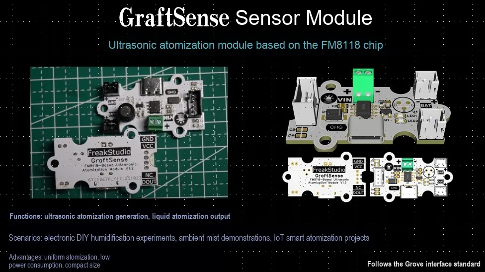
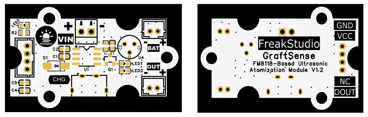
Ultrasonic Atomization Module Based on FM8118 Chip, with a circuit operating voltage of 5V, which forms a resonant circuit with the piezoelectric ceramic atomizing sheet via an inductor, and uses the AC voltage output by FM8118 at 108kHz with a 40% duty cycle to drive the atomizing sheet to atomize water.The module is equipped with Type-C charging port (with a fixed charging current of 350mA) and a lithium battery connection terminal, and also reserves a DB125-2P power supply interface; in addition, the power supply of MCU is isolated from the power supply of the atomization circuit. In actual use, it can work once connected to a battery, and can be powered via Type-C when the battery runs out. It is suitable for atomization scenarios such as humidifiers, providing a convenient hardware solution for ultrasonic atomization applications.
II. Introduction to Main Chips
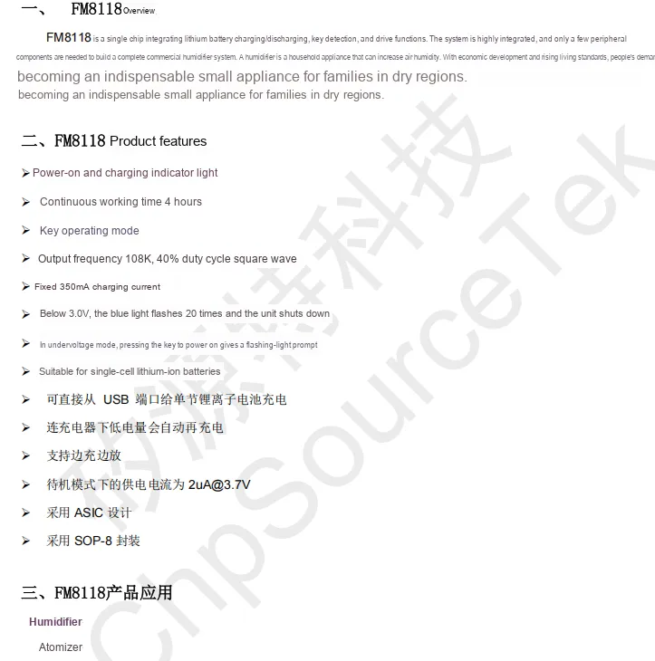
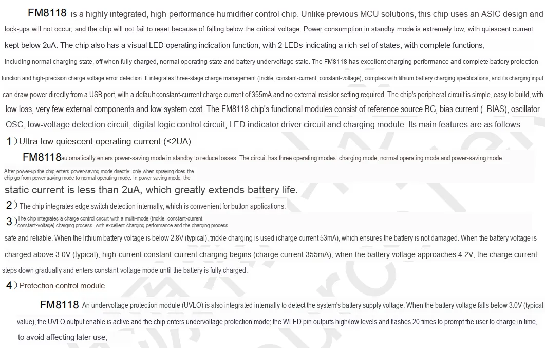
FM8118 is a highly integrated humidifier-specific control chip designed with ASIC technology, adapted for a single lithium-ion battery and compatible with USB port power supply. It features three-stage charging management including trickle charging, constant current charging and constant voltage charging, with a default constant current charging current of 355mA, and also supports simultaneous charging and discharging.It features a standby static current of less than 2uA with extremely low power consumption, and integrates key detection and LED status indication functions, which can indicate states such as charging and undervoltage. It can output a 108KHz square wave with a 40% duty cycle to drive the atomizing sheet, and is equipped with functions including undervoltage protection. With few peripheral components, low cost, and no risk of crash or failure to reset, it is purpose-built for the commercialization systems of humidifiers.
2.1 Chip Overview
2.2 Pin Definition
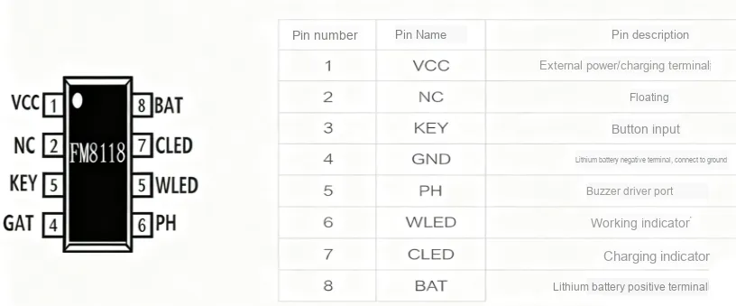
2.3 Functional Block Diagram
None.
2.4 Performance Parameters
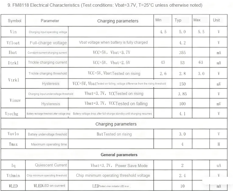
FM8118 Some of the electrical parameters are as follows:
- Charging Parameters:
- Charging Input Operating Voltage 4.5~5.5V, typical 5.0V;
- Full voltage 4.2V;
- Typical constant current charging current: 355mA (VCC= 5V, Vbat= 3.7V);
- Trickle charge current: 43~63mA (VCC= 5V, Vbat= 2.5V);
- Trickle Charge Threshold: 2.6~3.0V, with 150mV hysteresis;
- Typical undervoltage threshold for charging input: 3.85V, with 100mV hysteresis;
- Recharge threshold after battery voltage drop: 4.1V.
- Discharge Parameters:
- Battery undervoltage threshold 3.0V;
- Maximum operating duration Typically 4 hours.
- General Parameters:
- Quiescent Current Typical 2μA (Vbat= 3.7V, Power Saving Mode);
- Minimum operating threshold of the chip 2.4V;
- Typical WLED lighting current: 10mA.
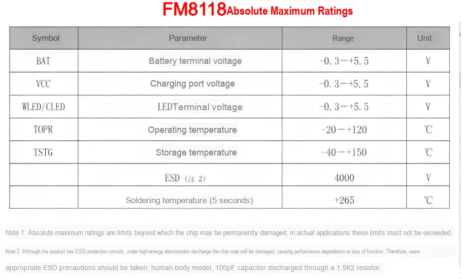
- Absolute Maximum Ratings:
- Voltage range of battery terminal, charging port and LED terminal: -0.3 ~ + 5.5V;
- Operating temperature: -20 to + 120°C.
2.5 Reference Circuit
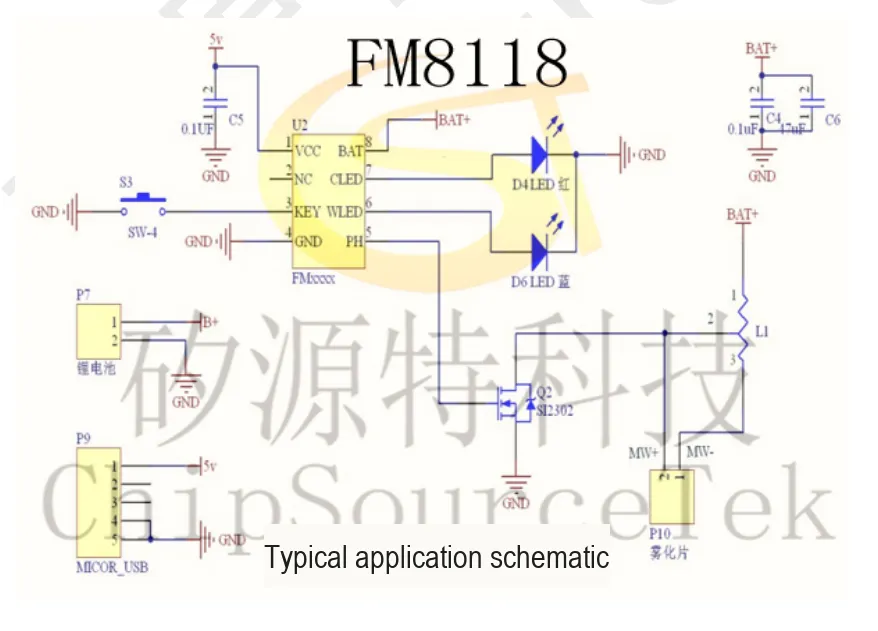
This is FM8118 's typical application circuit. Centering on the FM8118 chip, it supports dual power supply from 5V USB and lithium battery (with a filter capacitor installed at the battery terminal). Trigger control is realized via the key S3 (connected to the chip' s KEY pin), and the CLED and WLED pins are used to drive red/blue LEDs (D4, D6) for status indication. Meanwhile, the PH pin controls the MOS transistor Q2, which in turn drives the atomizing sheet connected in series with inductor L1 to work, realizing the key-triggered atomization function and corresponding status display.
2.6 Chip Configuration
None.
2.7 Communication Interfaces and Related Protocols
None.
2.8 PCB Routing Notes
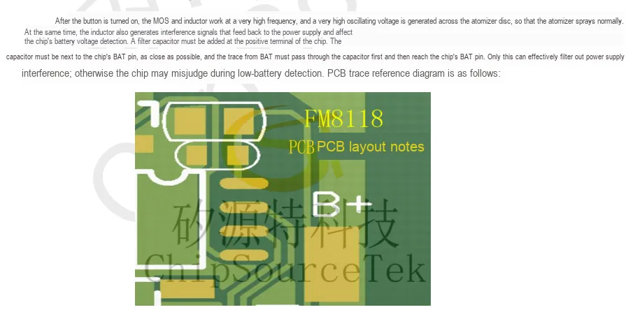
III. Circuit Engineering
3.1 Circuit Source Engineering
To obtain the circuit source project, please follow the official account [Freak Embedded]
3.2 Module Usage Instructions
SCH_Schematic-FM8118-Based Ultrasonic Atomizer Module-V1.2.0_2025-11-17.pdf 5.7 MB
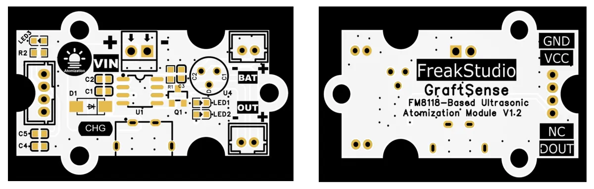
This module uses digital output DOUT: default high level, MCU outputs low level to pull it down; it can be directly connected to the main control GPIO port, and is suitable for scenarios such as trigger detection and status indication. Meanwhile, the DOUT interface equipped on the module is the access terminal for the atomizing sheet;The module is based on FM8118 as the core to implement the ultrasonic atomization function, supporting VIN external USB power supply or BAT battery power supply. LED1 and LED2 indicate the atomization working status and power status respectively; the OUT terminal can be connected to an atomizing chip to complete liquid atomization. It is suitable for scenarios such as small atomizers, maker project atomization demonstrations, and small environmental humidification, providing convenient ultrasonic atomization control and status monitoring capabilities for the system.
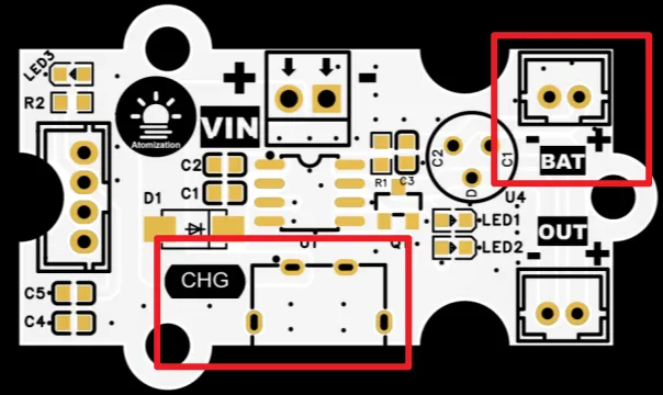
This module can use the USB interface to charge the battery.
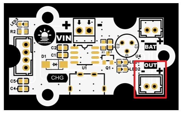
The OUT interface of this module is used to connect the microporous atomizing chip, which has no positive or negative polarity and can be connected according to the marks in the picture.
It should be noted that when using this module, you must use the BAT interface to connect the battery to supply power for the atomizing sheet, and it cannot work normally if only the Type-C interface is connected for power supply.
3.3 Application Experiment
Here, we use the GraftPort-RP2040 development board for testing, which is based on an ultrasonic atomizer module that uses the DIO interface to communicate with the main controller, and is powered by a connected battery.
Here, we first use the HY2.0-4P cable to connect the module to the GraftPort-RP2040 development board's DIO0 interface:
The module connections are shown in the following table:
Development Board Pins | Module Pins | Description |
Pin 6 |
| PWM output pins and high/low level output pins of the MCU |
Pin 7 |
| - |
- |
| Connect |
- |
| atomizing plate |
Here, we need to search for the relevant driver packages on uPyPI: https://upypi.net/zh/
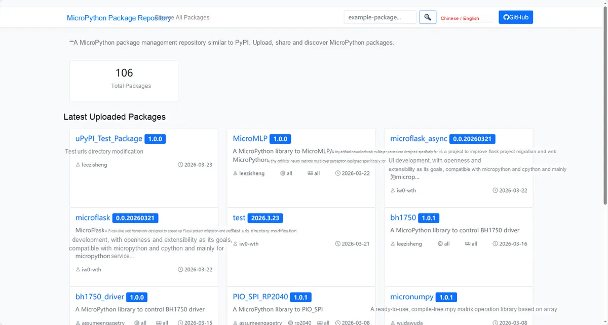
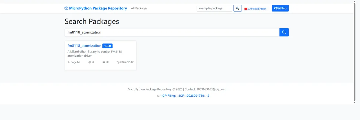
Enter fm8118_atomization to search, and the following will be displayed:
Click to copy the local installation command:
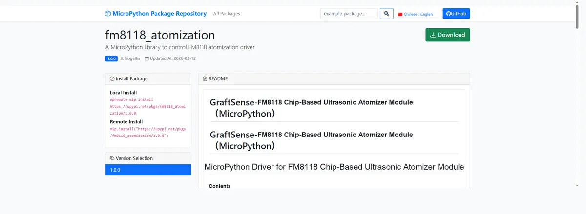
Here, we can use the mip tool to import module driver library code. Below are the usage commands for the mpremote tool:
mpremote mip install github:FreakStudioCN/GraftSense-Drivers-MicroPython/motor_drivers/fm8118_atomization_driverImport the ultrasonic atomizer module - MicroPython driver code, and copy the following main.py code into our project:
# Python env   : MicroPython v1.23.0
# -*- coding: utf-8 -*-
# @Time    : 2025/9/9 10:20 AM
# @Author  : 缪贵成
# @File    : main.py
# @Description : Atomizer module driver based on the FM8118 chip

# ======================================== Import Modules =========================================

import time
from fm8118_atomization import FM8118_Atomization

# ======================================== Global Variables ============================================

# ======================================== Functions ============================================

# ======================================== Custom Classes ============================================

# ======================================== Initialization configuration ===========================================

# Power-on delay of 3 s
time.sleep(3)
# Print debug information
print("FreakStudio:Testing the FM8118-based atomization module")

# Use GPIO6 to control the atomizer module
atomizer = FM8118_Atomization(pin=6)

# ========================================  Main Program  ============================================

try:
    while True:
        print("turn on")
        atomizer.on()
        print("status:", atomizer.is_on())
        time.sleep(10)

        print("turn off...")
        atomizer.off()
        print("status:", atomizer.is_on())
        time.sleep(10)

        print("toggle...")
        atomizer.toggle()
        print("status:", atomizer.is_on())
        time.sleep(10)

except KeyboardInterrupt:
    print("test stop")
Burn the code, the terminal output is as follows:
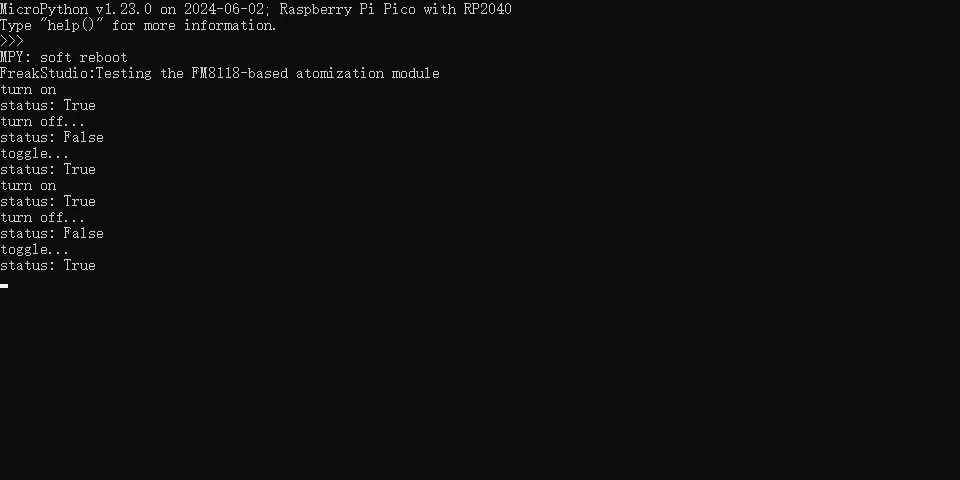
The code will implement the atomizer, with an interval of 10 seconds for on-off switching, and the cotton swab needs to be pre-soaked.
Atomization effect of the atomizer.
IV. Drivers
fm8118_atomization_driver.zip 4 KB
5. BOM & Recommended Alternative Parts
None.
VI. Revision History
Document Version | Date of Revision | Modifier | Modify Content |
v1.0 | 2025-11-17 | Zero Kōkō | Initialize the document |
v1.1 | 2025-12-30 | Li Zisheng | Added application experiments and production files |
v1.2 | 2025-12-31 | Xin Ruili | Create an open version of the document based on the internal document version v1.1. |
v1.3 | 2026-03-29 | Xin Ruili | Modified the application experiment section |
VII. Relevant Materials
7.1 Chip Datasheet
FM8118 DataSheet.pdf 1.2 MB
7.2 Unique Icons for PCB Silk Screen