Contents
- I. Module Introduction
- II. Introduction to Major Chips
- 2.1 Chip Overview
- 2.2 Pin Definition
- 2.3 Functional Block Diagram
- 2.4 Performance Parameters
- 2.5 Reference Circuit
- 2.6 Chip Configuration
- 2.7 Communication Interfaces and Related Protocols
- 2.8 PCB Routing Precautions
- III. Circuit Source Engineering and Module Usage Instructions
- 3.1 Circuit Source Engineering
- 3.2 Module Usage Instructions
- 3.3 Application Experiment
- IV. Drivers
- 5. BOM & Recommended Alternative Parts
- VI. Revision History
- VII. Relevant Materials
- 7.1 Chip Datasheet
- 7.2 PCB Silkscreen Specific Icons
I. Module Introduction
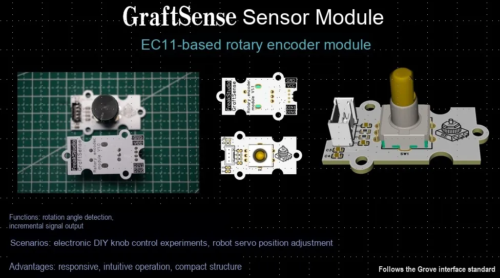
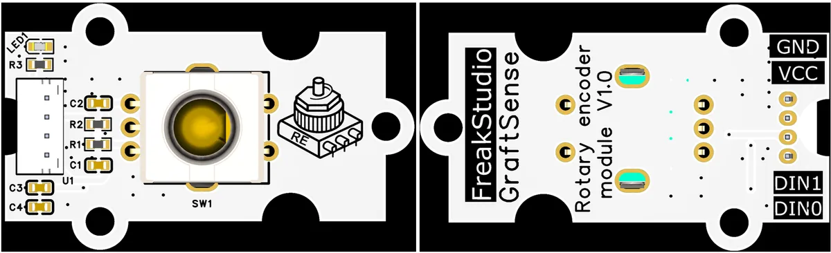
EC11-based Rotary Encoder Module is a EC11 -based rotary encoder module that integrates a filter circuit, status indicator light and sensor interface. With the EC11 encoder as the core, it can output two encoded signals, namely RE_DT and RE_CLK, and is equipped with a key function. Suitable for maker projects, electronic device development and other scenarios, it realizes precise rotary control and interactive feedback, and provides a reliable solution for system parameter adjustment, human-computer interaction and other demands.
II. Introduction to Major Chips
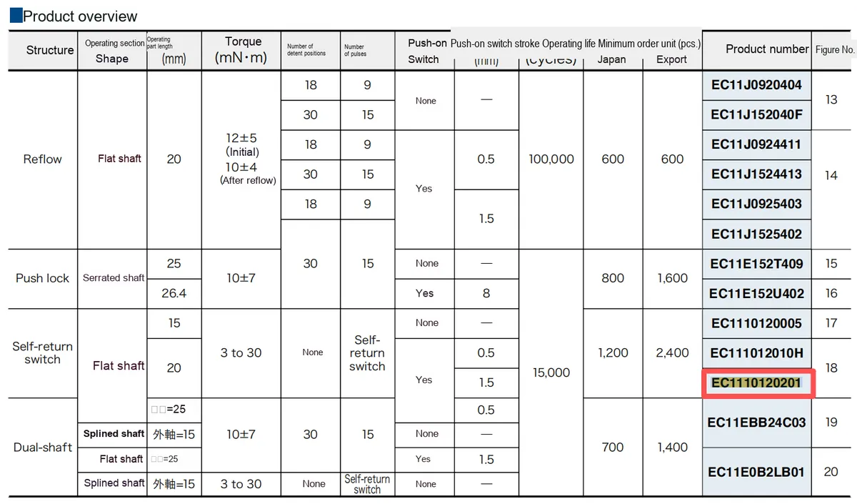
Here, we use the EC11 rotary encoder component with 20 pulses and 20 positioning points.
2.1 Chip Overview
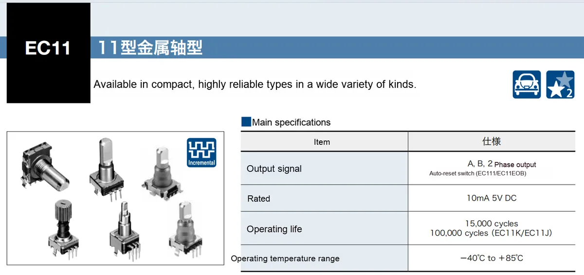
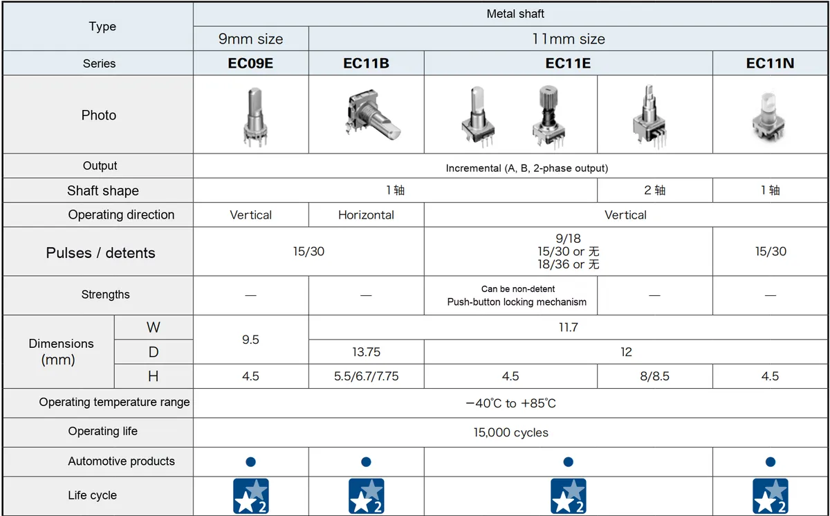
EC11 series rotary encoder is an incremental encoder based on mechanical contacts, which is widely used in audio equipment, home appliance control, industrial electronics and human-machine interaction interfaces. Its main function is to convert rotary angular displacement into electrical pulse signals for detecting rotation direction and step position, and it can be optionally equipped with a key function.
2.2 Pin Definition
EC11 typically has 5 pins, as shown in the following figure: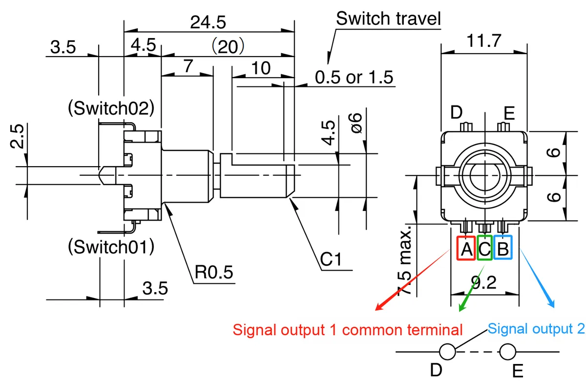
APin (Red) Signal Output 1: Outputs a rotation pulse signal.Pin B(blue) Signal Output 2: It also outputs a pulse signal, but there is a phase difference withPin A.CPin (Green) Common Terminal:AandBsignal channels' common ground terminal.D,Epins: The two terminals of the push switch, which are short-circuited when the button is pressed.
2.3 Functional Block Diagram
20 pulses and 20 positioning points EC11 rotary encoder component has the following structure:
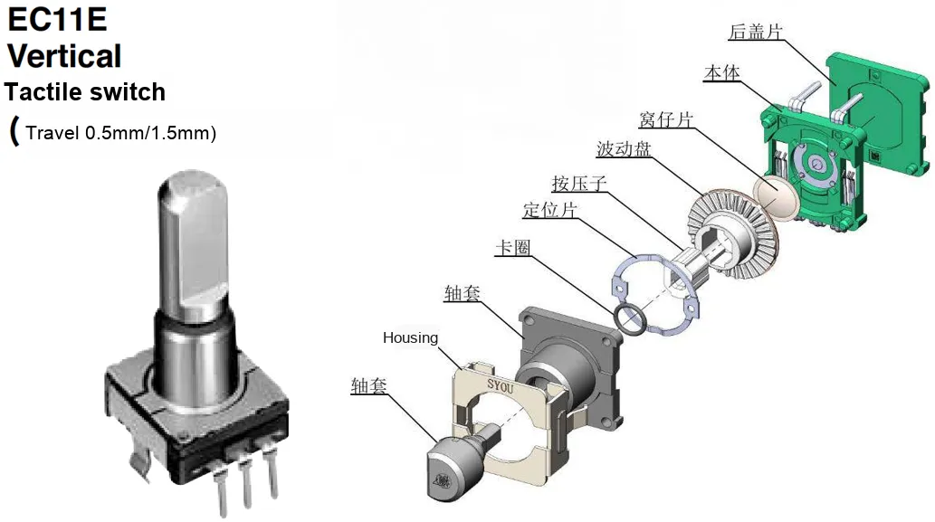
The names and functions of the respective components are as follows:
- Encoding Wheel: A core component of an encoder that generates signals via rotational operation. It is fitted with equally spaced conductive strips, which sequentially come into contact with output contacts as the wheel rotates, thereby generating pulse signals;
- Detent plate: It locates each rotational position and provides mechanical feedback, giving the encoder a distinct tactile feel when turned. The
EC11we use features 20 detents, meaning there is a notch for every 18 degrees of rotation. - Contact: Works in coordination with the wobble plate to detect the position change of the conductive strip and generate a signal;
- Shaft sleeve and housing: They provide physical structural support for the encoder, and electronic components and pins are usually mounted on the housing.
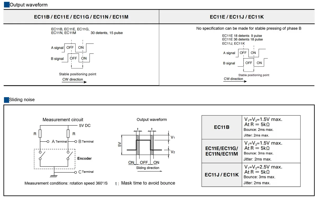
Its working principle is that EC11 outputs incremental rotation signals through two signal channels (Pin A and Pin B). During rotation, staggered pulses are generated in the A and B signal channels; by comparing the phase relationship between the two, the rotation direction (clockwise or counterclockwise) can be determined:
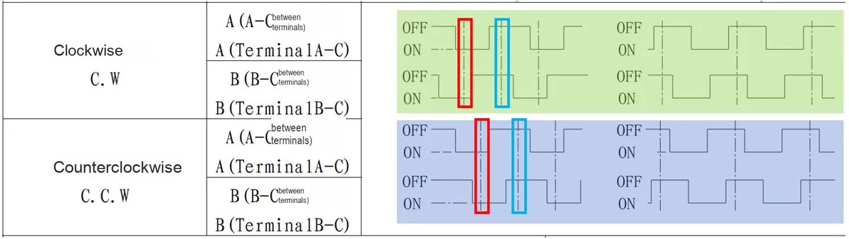
Simply put, it is as follows:
- When rotating clockwise,
phase Aleadsphase Bby 90 degrees, that is,when phase Ais at the falling edge,phase Bis at low level;when phase Ais at the rising edge,phase Bis at high level. - When rotating counterclockwise,
phase Bleadsphase Aby 90 degrees, that is,when phase Ais at the falling edge,phase Bis at high level;when phase Ais at the rising edge,phase Bis at low level.
It is not difficult to find that whenever phase A or phase B undergoes a level transition, the rotation direction can be determined simply by detecting the state of the other phase:
- Clockwise: both phases are on the rising edge at the same time or on the falling edge at the same time;
- Counterclockwise: the two phases do not present rising edges simultaneously or falling edges simultaneously;
At the same time, the number of rotation steps (increment) can be determined in combination with pulse counting.
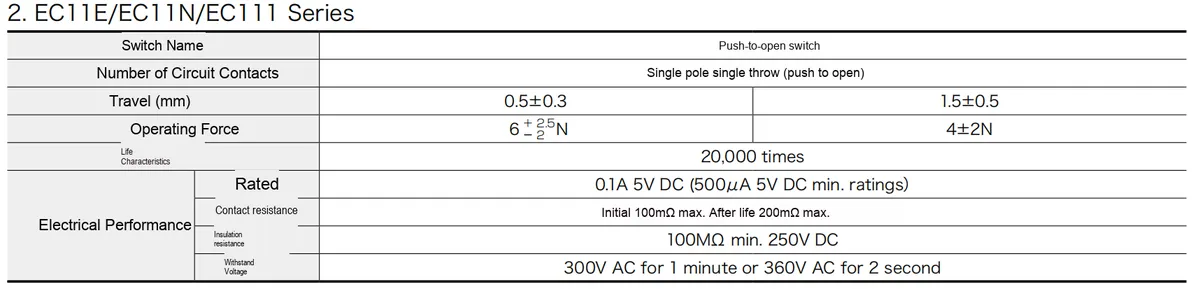
Here, the EC11 rotary encoder also comes with a push switch (pins D and E): when the encoder is pressed, its internal mechanical structure triggers a key signal, which is commonly used for control or operation confirmation.
2.4 Performance Parameters
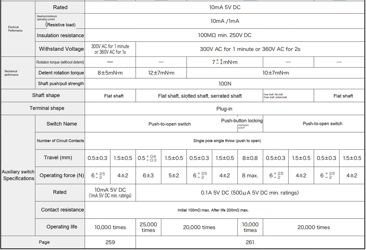
2.5 Reference Circuit
None.
2.6 Chip Configuration
None.
2.7 Communication Interfaces and Related Protocols
No communication interface.
2.8 PCB Routing Precautions
None.
III. Circuit Source Engineering and Module Usage Instructions
3.1 Circuit Source Engineering
To obtain the source project of the circuit, please follow the official account [Freak Embedded]
3.2 Module Usage Instructions
The schematic diagram of this module is shown below:
SCH_EC11-Based_Rotary_Encoder_Module_v1.0_2025-10-23.pdf 1.8 MB
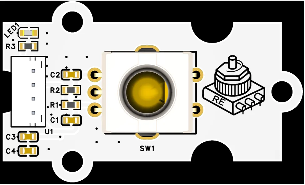
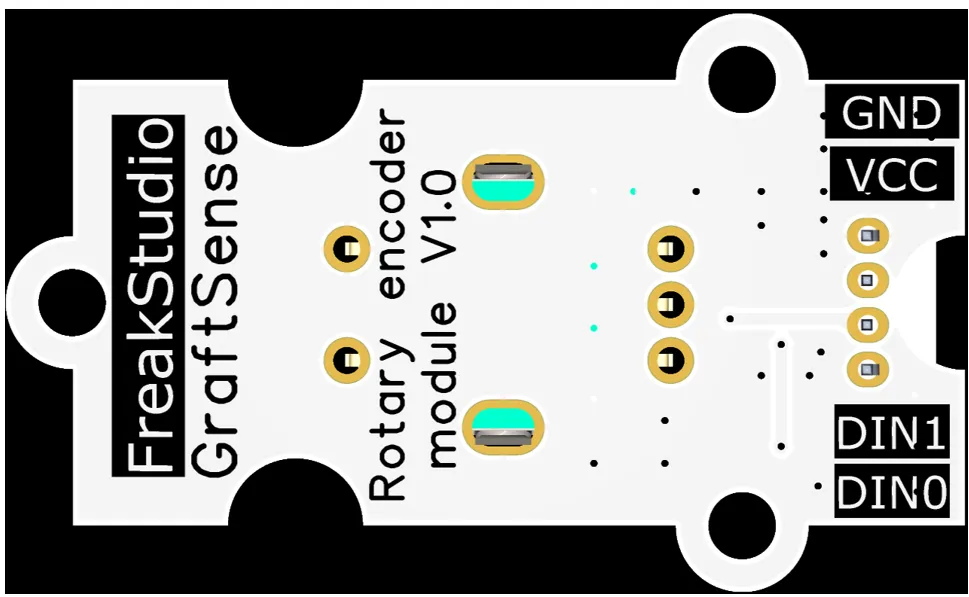
This module provides an interface for outputting a pair of pulse signals (DIN0 and DIN1): The DIN0 interface corresponds to the RE_DT / A phase signal, and the DIN1 interface corresponds to the RE_CLK / B signal. As a pair of pulse signals output by the rotary encoder, they can be used to implement rotation direction identification and counting functions, and provide precise rotation control feedback for external devices such as microcontrollers.
Its working principle is that EC11 outputs incremental rotation signals through two signal channels (Pin A and Pin B). During rotation, staggered pulses are generated in the A and B signal channels; by comparing the phase relationship between the two, the rotation direction (clockwise or counterclockwise) can be determined:
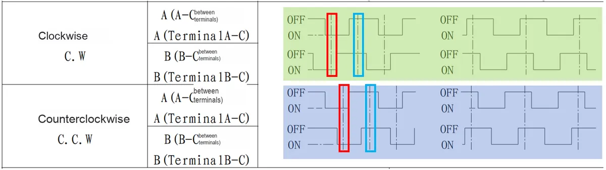
Simply put, it is as follows:
- When rotating clockwise,
phase Aleadsphase Bby 90 degrees, that is:when phase Ais at the falling edge,phase Bis at low level;when phase Ais at the rising edge,phase Bis at high level. - When rotating counterclockwise,
phase Bleadsphase Aby 90 degrees, that iswhen phase Ais at the falling edge,phase Bis at high level;when phase Ais at the rising edge,phase Bis at low level.
It is not difficult to find that whenever phase A or phase B undergoes a level transition, the rotation direction can be determined simply by detecting the state of the other phase:
- Clockwise: both phases are either on the rising edge or the falling edge simultaneously;
- Counterclockwise: the two phases do not present rising edges simultaneously or falling edges simultaneously;
At the same time, the number of rotation steps (increment) can be determined in combination with pulse counting.
Here, our module does not have an output interface for the push switch (pin D, pin E).
3.3 Application Experiment
Here, we use the GraftPort-RP2040 development board for testing, and connect the EC11-based rotary encoder module to communicate with the main controller via the DIO interface.
Here, we first use the HY2.0-4P connection cable to connect the module to the GraftPort-RP2040 development board's DIO0 interface:
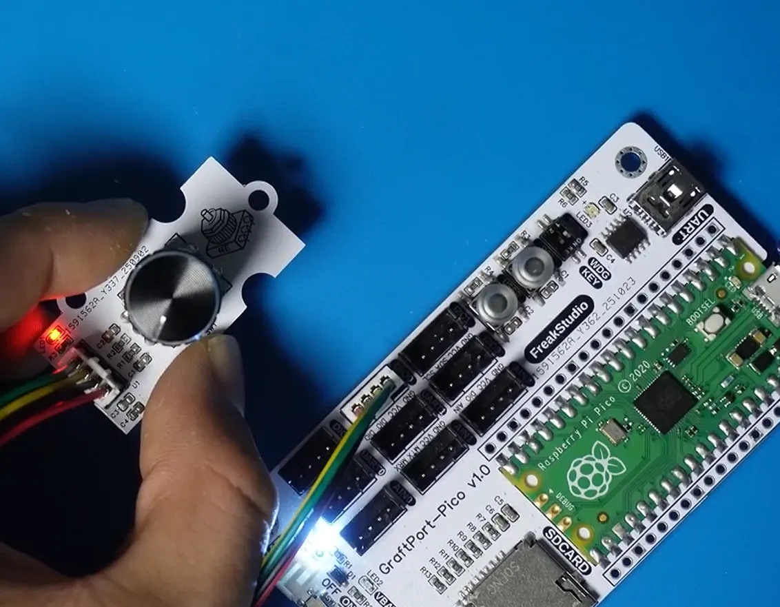
The module connections are shown in the following table:
Development Board Pins | Module Pins | Description |
Pin 6 |
| Phase |
Pin 7 |
|
|
Here, we need to search for the relevant driver packages on uPyPI: https://upypi.net/zh/
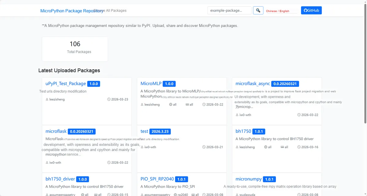
Enter rotaryencoder_driver to search, and the following will be displayed:

Click to copy the local installation command:
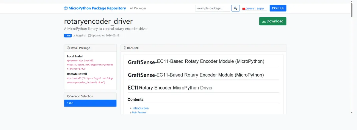
Here, we can use the mip tool to import module driver library code. Below are the usage commands for the mpremote tool:
mpremote mip install github:FreakStudioCN/GraftSense-Drivers-MicroPython/input/rotaryencoder_driverAfter importing the rotary encoder driver - MicroPython driver code, copy the following main.py code into our project:
# Python env   : MicroPython v1.23.0
# -*- coding: utf-8 -*-
# @Time    : 2024/9/19 7:46 PM
# @Author  : Li Qingshui
# @File    : main.py
# @Description : Timer class experiment, read the value of a rotary encoder and use a timer for software debouncing

# ======================================== Import Modules =========================================

# Import time-related modules
import time
# Import custom driver module
from processbar import ProgressBar
from ec11encoder import EC11Encoder

# ======================================== Global Variables ============================================

# ======================================== Functions ============================================

# ======================================== Custom Classes ============================================

# ======================================== Initialization ==========================================

# Power-on delay of 3 s
time.sleep(3)
# Print debug information
print("FreakStudio : Using GPIO read Rotary Encoder value, use software debounce by timer")

# Create an EC11 rotary encoder object, using GPIO10 and GPIO11 as phase A and phase B, and GPIO12 as the button
# If you want to change the rotation direction in which the encoder count increases (for example, from counterclockwise increasing to clockwise increasing)
# just swap the values of the pin_a and pin_b parameters when initializing the encoder object
encoder = EC11Encoder(pin_a=6, pin_b=7)
# Create the terminal progress bar object to display progress; 20 rotations reach 100%
progress_bar = ProgressBar(max_value=20)

# ========================================  Main Program  ===========================================

# Get the rotation count and button state in the main loop
while True:
    # Get the rotation count
    current_rotation = encoder.get_rotation_count()
    print(f"Rotation count: {current_rotation}")
    # Update the progress bar
    progress_bar.update(current_rotation)
    # When the button is pressed, reset the progress bar
    if encoder.is_button_pressed():
        progress_bar.reset()
    # Update every 10ms
    time.sleep_ms(10)
Burn the code, open a terminal, and use the mpremote tool to connect to the main controller; the output is as follows:
It can be seen that when we select an encoder, the terminal output will increase or decrease synchronously:
IV. Drivers
rotaryencoder_driver.zip 12 KB
5. BOM & Recommended Alternative Parts
None.
VI. Revision History
Document Version | Date of Revision | Modifier | Modified Content |
v1.0 | 2025-09-04 | ben0i0d | Complete the initial version of schematic diagram and PCB design |
v1.1 | 2025-10-23 | Li Zisheng | Added Section 2.8 PCB Routing Notes Revised Section 3, Instructions for Circuit Source Engineering and Module Usage, and added a secondary heading: 3.1 Circuit Source Engineering, 3.2 Module Usage Instructions, 3.3 Application Experiments The BOM sheet has not been finally checked, the driver has not been re-verified, and the 3.3 application experiment Not yet specified. |
v1.2 | 2025-12-29 | Li Zisheng | Added application experiments and production files |
v1.3 | 2025-12-31 | Xin Ruili | Create an open version of the document based on the internal document version v1.2. |
v1.4 | 2026-03-29 | Xin Ruili | Modified the application experiment section. |
VII. Relevant Materials
7.1 Chip Datasheet
C470795_Rotary_Encoder_EC1110120201_Datasheet_WJ277337.PDF 2.4 MB
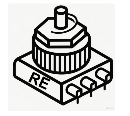
7.2 PCB Silkscreen Specific Icons