Contents
- I. Module Introduction
- II. Introduction to Main Chips
- 2.1 Chip Overview
- 2.2 Pin Definition
- 2.3 Functional Block Diagram
- 2.4 Performance Parameters
- 2.5 Reference Circuit
- 2.6 Chip Configuration
- 2.7 Communication Interfaces and Related Protocols
- 2.8 PCB Routing Precautions
- III. Circuit Engineering
- 3.1 Circuit Source Engineering
- 3.2 Module Usage Instructions
- 3.3 Application Experiment
- IV. Drivers
- 5. BOM & Recommended Alternative Parts
- VI. Revision History
- VII. Relevant Materials
- 7.1 Chip Datasheet
- 7.2 Unique Icons for PCB Silk Screen
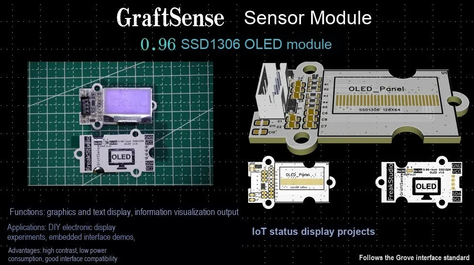
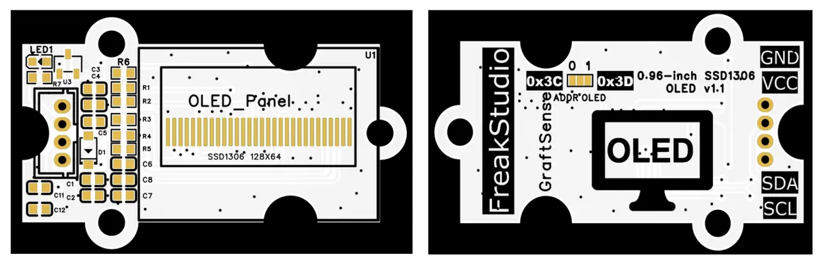
I. Module Introduction
0.96-inch SSD1306-OLED module adopts the SSD1306 driver chip and realizes data transmission through the I2C communication interface. This module is suitable for small-sized display scenarios of various embedded devices, can clearly present information such as text and graphics, and provides a convenient monochrome OLED display solution for systems like microcontrollers.
II. Introduction to Main Chips
2.1 Chip Overview
SSD1306 is a single-chip CMOS OLED/PLED driver with a controller for OLED dot-matrix graphic display systems. It consists of 128 SEGs (column outputs) and 64 COMs (row outputs). With built-in contrast controller, display RAM (GDDRAM) and oscillator, it reduces the number of external components and power consumption. This chip features 256-level brightness control, and can receive data or commands via the following communication methods:
- 8-bit 6800/8080 Serial-Parallel Interface
- 3/4-wire Serial Peripheral Interface
- I2C interface
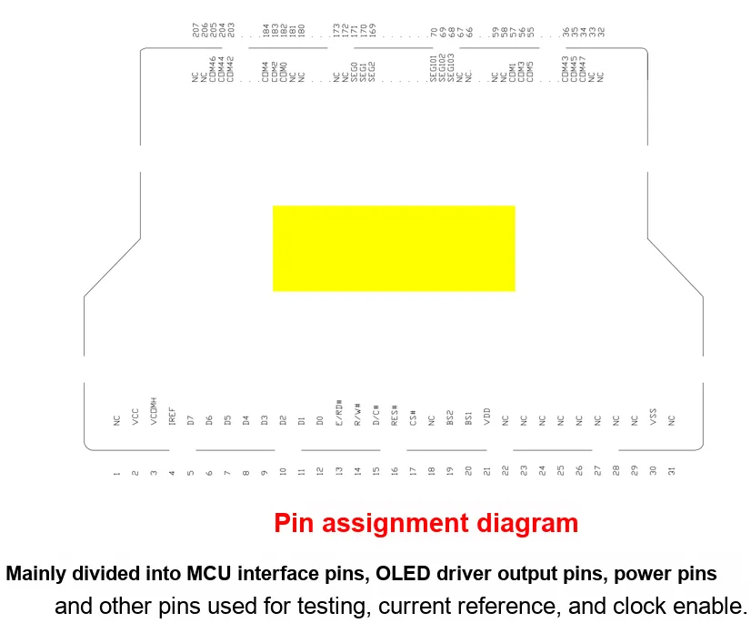
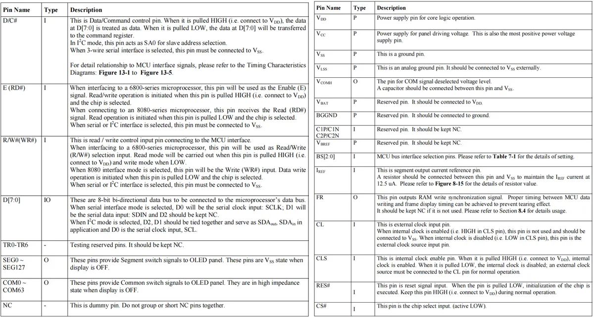
2.2 Pin Definition
The following is SSD1306 the function description of each pin of the OLED screen:
2.3 Functional Block Diagram
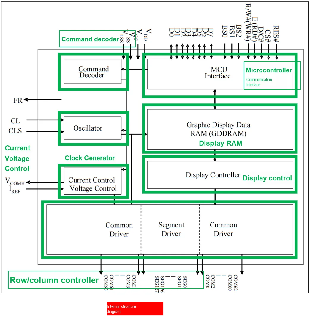
- Instruction Decoder Module (Command Decoder): It parses instructions from the MCU interface, converts them into internally executable control signals, and coordinates the operation of each module.
- MCU Interface Module (MCU Interface): Communicates with an external MCU via pins such as D0-D7, BS0-BS2, and R/W# to implement command reception and data interaction.
- Oscillator Module: Receives CL and CLS inputs, generates the clock signals required for chip operation, and provides a timing reference for each module.
- Graphic Display Data RAM (GDDRAM): A module that stores graphics display data, acting as the "data warehouse" for display content to be accessed by the display controller.
- Display Controller Module: It reads data from the GDDRAM and generates signals to control the display driver, serving as the core unit of display control.
- Current and Voltage Control Module (Current Control Voltage Control): Receives the inputs of V_COMH and I_REF, controls the current and voltage of the display driver to ensure stable display performance.
- drive module
- Common Driver, Segment Driver : convert the signals from the display controller into current/voltage signals that drive the display panel, so as to turn pixels on and off.
Graphical Display Application Scenarios:
- Instruction and Data Transmission: The external MCU sends display commands and data via the MCU interface → the Command Decoder parses the commands → the data is stored in the GDDRAM.
- Display Driver: The Display Controller reads data from GDDRAM → generates control signals → adjusts driving parameters via Current Control and Voltage Control → drives the display panel through the Common Driver and Segment Driver to realize graphic display.
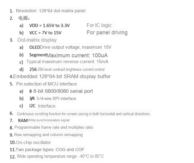
2.4 Performance Parameters
2.5 Reference Circuit
None.
2.6 Chip Configuration
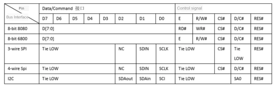
SSD1306 supports multiple communication modes: 8-bit 6800 series, 8-bit 8080 series, 4-wire SPI, 3-wire SPI and IIC interfaces. This module adopts the I2C communication mode, and the configuration of this chip has been set via hardware. If you have other requirements, please refer to the table below.
2.7 Communication Interfaces and Related Protocols
The SSD1306 chip operates at a supply voltage ranging from 1.65V to 3.3V, whereas OLED display screens require a supply voltage of 7V to 15V. We only need to provide a 5V voltage input to the entire module, and the built-in charge pump circuit of the SSD1306 chip will convert the voltage to meet the power supply requirements of both the SSD1306 chip and the display screen.
Simply put, the basic principle of controlling SSD1306 chip to drive OLED screen for display is as follows:
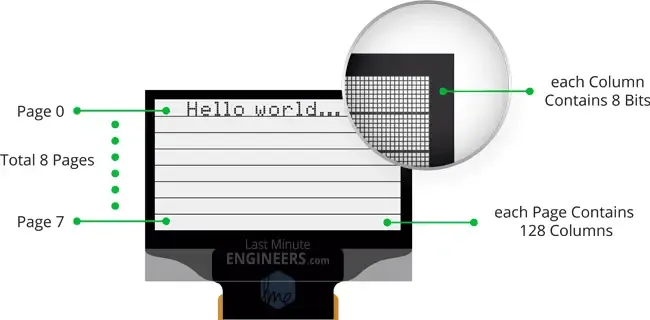
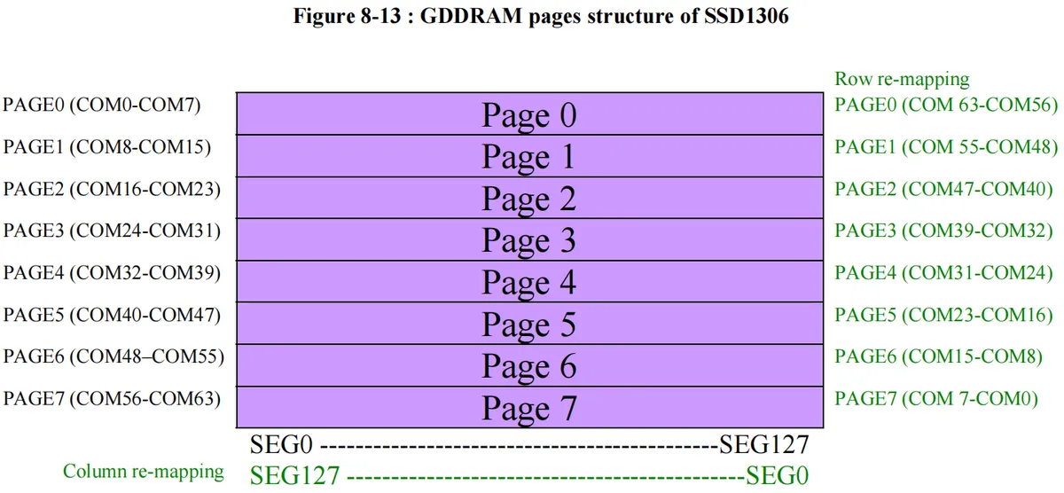
SSD1306 stores the bit data of the entire OLED screen to display the image through the internal 1KB size graphic display data RAM ( GDDRAM ). This 1KB memory area is divided into 8 pages ( PAGE0 ~ PAGE7 ), and every 8 rows of pixels (8 * PIXEL ) are recorded as one page. There are 128 columns of SEG in one page, and each column can store 8 bits or one byte of data. By writing data to eight pixels of a column of SEG , we can control the display effect of this column. Similarly, we can control the display effect of the entire screen.
To display the entire screen, we need to write 1024 bytes:
8 pages x 128 segments x 8 bits of data = 8192 bits = 1024 bytes = 1KB memory
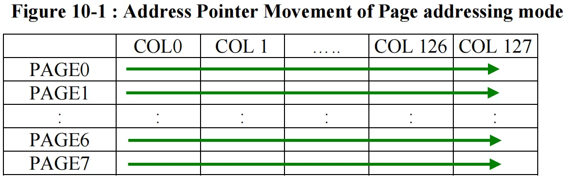
In page addressing mode, addressing is performed only within a single page (PAGEn), and the address pointer will not jump to other pages. Each time after writing 1 byte of display data to GDDRAM, the column pointer is automatically incremented by 1. When all 128 columns have been addressed, the column pointer will point back to SEG0 while the page pointer remains unchanged. The user must set a new page and column address to access the RAM content of the next page. The page addressing mode allows users to conveniently modify data within a small area.
In page addressing mode, addressing is performed only within a single page. Each time 1 byte of display data is written to GDDRAM, the column pointer is automatically incremented by 1. After all 128 columns have been addressed, the column pointer will return to the starting column position, namely SEG0, while the page pointer remains unchanged. The user must set a new page and column address to access the RAM content of the next page. The following figure is a schematic diagram of the column pointer movement sequence in page addressing mode:
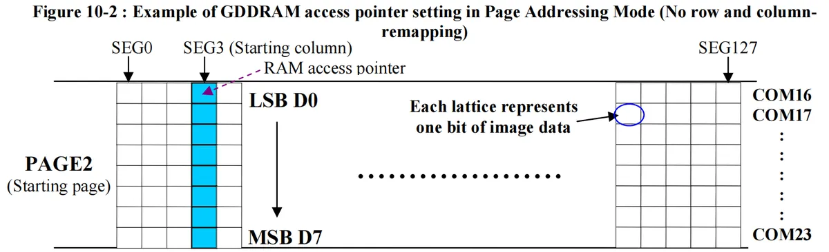
When we use the page addressing mode, when operating on a column of data within one page, the operation can only be performed in bytes, that is, writing 8 bits of data at a time. The data bit D0 is written to the top row, and the data bit D7 is written to the bottom row (from top to bottom, from low to high):
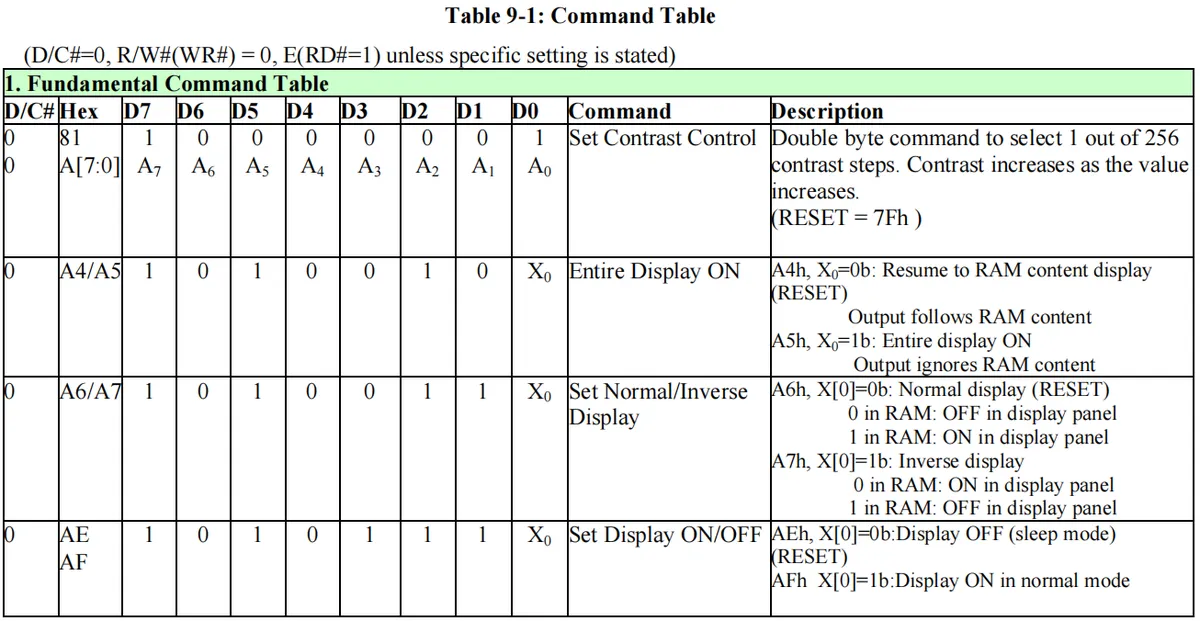
peripheral of the Raspberry Pi Pico. The control commands for the OLED screen by sending commands and data to the SSD1306 via the I2C peripheral of the Raspberry Pi Pico. The control commands for the SSD1306 mainly consist of the following parts:
- Basic Commands: Commands for setting contrast, full-screen full brightness, normal/inverted display, and turning the display on/off, etc.
- Address Instruction: Instructions related to setting the addressing mode and the parameters required for different addressing modes.
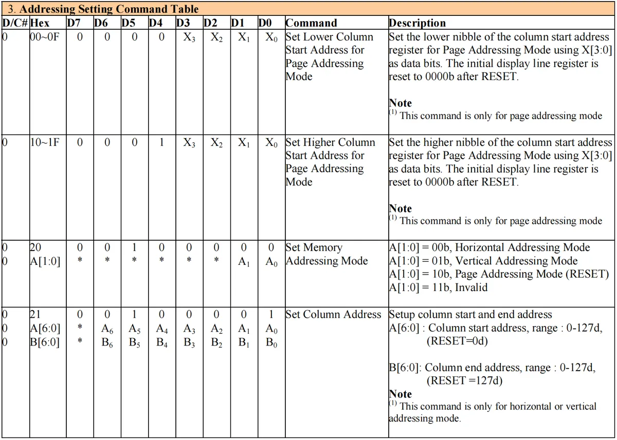
- Hardware Instruction: Set
GDDRAMstart line,COMscanning direction,SEGmapping relationship and other display-related instructions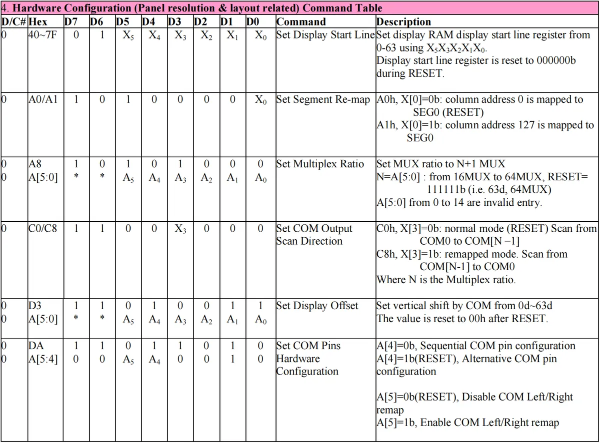
- Timing commands: commands related to clock, such as setting display clock frequency division factor,
fosc, precharge cycle andVCOMHoutput high level, etc.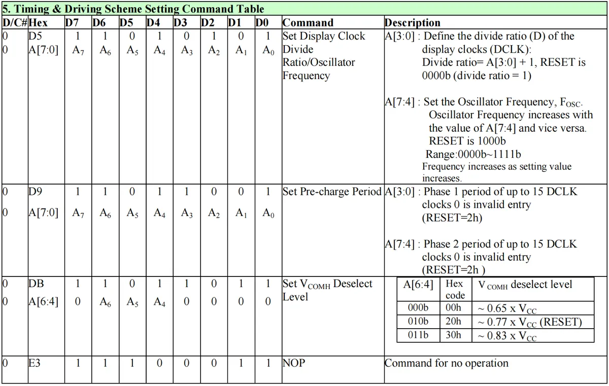
- Scrolling commands: including commands to disable or enable horizontal and vertical scrolling functions, as well as to set parameters such as scrolling area and speed.
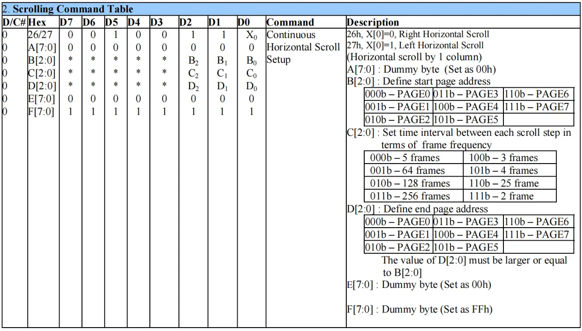
For more instructions and their specific meanings, please visit the following link:
https://www.alldatasheet.com/view.jsp?Searchword=Ssd1306
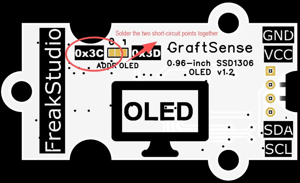
It should be noted here that the slave address of the OLED screen can actually be changed. When using the I2C interface, SSD1306 allows up to two 7-bit I2C addresses, which are also switched by pulling down and up through the corresponding IO port. The general default is 0x3C. On the back of some modules (not all, some PCBs are not reserved), you can see the I2C address option prompt. When you need to change the module I2C address, you only need to remove the resistor at the prompt position and solder it to the other end. Note that the I2C address on the board is the value after adding the zeroth read-write bit.
2.8 PCB Routing Precautions
None.
III. Circuit Engineering
3.1 Circuit Source Engineering
To obtain the circuit source project, please follow the official account [Freak Embedded]
3.2 Module Usage Instructions
SCH_Schematic1_0.96-inch SSD1306-OLED Module-V1.1_2025-11-13.pdf 1.9 MB
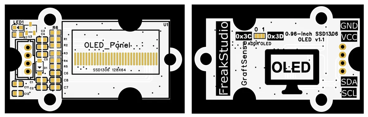
This module provides an I2C communication interface: it supports standard I2C communication rates, and can flexibly configure two ADDR pin-configurable 0x3C and 0x3D I2C device addresses. It is compatible with 3.3V/5V logic levels, and can stably transmit text, graphics and other display data for monochrome OLED with 128×64 resolution. It is suitable for scenarios such as information display for maker projects, status display of embedded devices, and data visualization of small electronic systems, providing the system with convenient OLED display data interaction capability.
Here, before using the module, we need to first solder the ADDR short-circuit point settings OLED screen address on the back.
3.3 Application Experiment
Here, we use the GraftPort-RP2040 development board for testing, and connect the 0.96-inch SSD1306-OLED module to communicate with the main controller via the I2C interface.
Here, we need to set the address bits in advance by soldering two short-circuit points:
Here, we first use the HY2.0-4P connection cable to connect the module to the GraftPort-RP2040 development board's I2C0 interface:
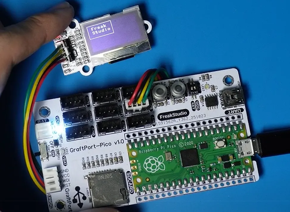
The module connections are shown in the following table:
development board pins | Module Pins | Description |
Pin 4 |
|
|
Pin 5 |
|
|
Here, we need to search for the relevant driver packages on uPyPI: https://upypi.net/zh/
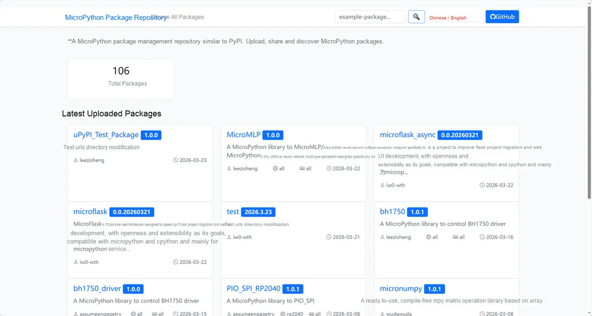
Enter ssd1306_driver to search, and the following will be displayed:
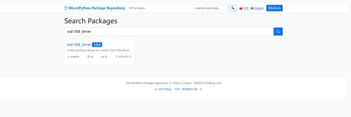
Click to copy the local installation command:
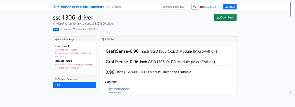
You can download it via the mip tool. Below are the usage commands for the mpremote tool:
mpremote mip install github:FreakStudioCN/GraftSense-Drivers-MicroPython/lighting/ssd1306_driverAfter importing the driver code for the 0.96-inch SSD1306-OLED module for MicroPython, copy the following main.py code into our project:
# Python env   : MicroPython v1.23.0
# -*- coding: utf-8 -*-
# @Time    : 2024/7/3 9:34 PM
# @Author  : Li Qingshui
# @File    : main.py
# @Description : I2C class experiment, mainly reads the serial gyroscope data and displays it on the OLED screen

# ======================================== Import Modules ========================================

# Import the SSD1306_I2C class from the SSD1306 module
from ssd1306 import SSD1306_I2C
# Hardware-related modules
from machine import I2C, Pin
# Import time-related modules
import time
# System-related modules
import os

# ======================================== Global Variables ============================================

# OLED screen address
OLED_ADDRESS = 0

# ======================================== Functions ============================================

# ======================================== Custom Classes ============================================

# ======================================== Initialization ==========================================

# Delay 3 s to wait for the device to finish powering up
time.sleep(3)
# Print debug message
print("FreakStudio: Testing OLED display")

# Create a hardware I2C instance using the I2C1 peripheral, with a clock frequency of 400KHz, SDA pin 4, and SCL pin 5
i2c = I2C(id=0, sda=Pin(4), scl=Pin(5), freq=400000)

# Output all files in the current directory
print('START LIST ALL FILES')
for file in os.listdir():
    print('file name:',file)

# Start scanning for devices on the I2C bus and return a list of slave addresses
devices_list = i2c.scan()
print('START I2C SCANNER')

# If devices_list is empty, no device is connected to the I2C bus
if len(devices_list) == 0:
    print("No i2c device !")
# If not empty, print the slave device addresses
else:
    print('i2c devices found:', len(devices_list))
    # Iterate over the slave device address list
    for device in devices_list:
        print("I2C hexadecimal address: ", hex(device))
        if device == 0x3c or device == 0x3d:
            OLED_ADDRESS = device

# Create an SSD1306 OLED screen instance, width 128 pixels, height 64 pixels, without external power supply
oled = SSD1306_I2C(i2c, OLED_ADDRESS, 128, 64,False)
# Print a prompt message
print('OLED init success')

# First clear the screen
oled.fill(0)
oled.show()
# The (0,0) origin is at the top-left corner of the screen, with the positive x-axis to the right and the positive y-axis downward
# Draw a rectangle outline
oled.rect(0, 0, 64, 32, 1)
# Display text
oled.text('Freak', 10, 5)
oled.text('Studio', 10, 15)
# Display an image
oled.show()
# ========================================  Main Program  ============================================

while True:
    time.sleep(0.1)
To flash the code, open a terminal and use the mpremote tool to connect to the main controller; the output is as follows:
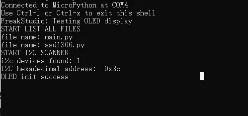
An oled screen displays the FreakStudio logo.
IV. Drivers
ssd1306_driver.zip 10 KB
5. BOM & Recommended Alternative Parts
None.
VI. Revision History
Document Version | Revision Date | Modifier | Revised Content |
v1.0 | 2025-11-13 | Xing Gao | Initialize Document |
v1.1 | 2025-12-29 | Li Zisheng | Added application experiments and production files |
v1.2 | 2025-12-31 | Sin Ruili | Create an open version of the document based on the internal document version v1.1. |
v1.3 | 2026-03-29 | Sin Ruili | Modified the application experiment section |
VII. Relevant Materials
7.1 Chip Datasheet
SSD1306 (OLED Driver Chip) Chinese Manual.pdf 6.1 MB
7.2 Unique Icons for PCB Silk Screen