Contents
- I. Module Introduction
- II. Introduction to Main Chips
- 2.1 Chip Overview
- 2.2 Pin Definition
- 2.3 Functional Block Diagram
- 2.4 Performance Parameters
- 2.5 Reference Circuit
- 2.6 Chip Configuration
- 2.7 Communication Interfaces and Related Protocols
- 2.8 PCB Routing Precautions
- III. Instructions for Circuit Engineering and Module Usage
- 3.1 Circuit Source Engineering
- 3.2 Module Usage Instructions
- 3.3 Application Experiment
- IV. Drivers
- 5. BOM & Recommended Alternative Parts
- VI. Revision History
- VII. Relevant Materials
- 7.1 Chip Datasheet
- 7.2 Unique Icons for PCB Silk Screen
I. Module Introduction
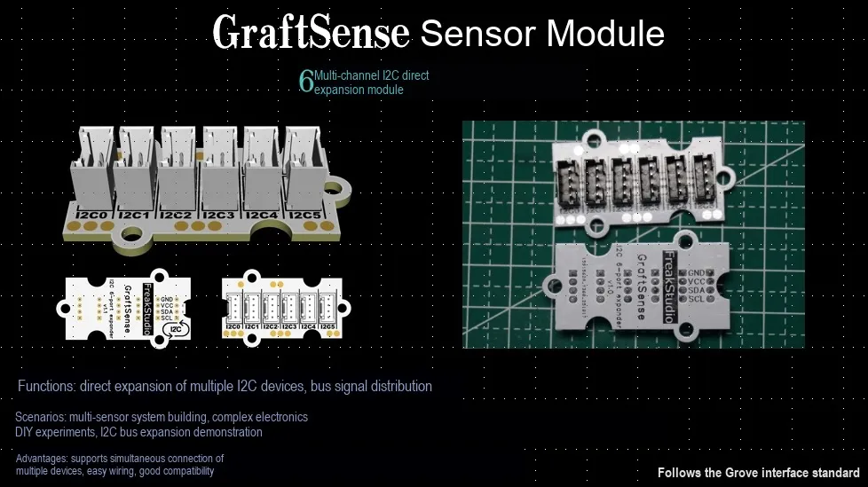
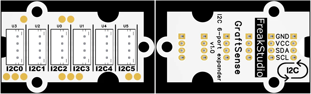
6-channel I2C direct connection expansion module can provide I2C0 to I2C5 total 6 channels of I2C interfaces, supports direct expansion of I2C communication channels, is applicable to scenarios such as maker development and industrial control, and provides a convenient hardware solution for embedded systems to connect multiple I2C devices.
II. Introduction to Main Chips
2.1 Chip Overview
None.
2.2 Pin Definition
None.
2.3 Functional Block Diagram
None.
2.4 Performance Parameters
None.
2.5 Reference Circuit
None.
2.6 Chip Configuration
None.
2.7 Communication Interfaces and Related Protocols
None.
2.8 PCB Routing Precautions
None.
III. Instructions for Circuit Engineering and Module Usage
3.1 Circuit Source Engineering
To obtain the circuit source project, please follow the official account [Freak Embedded]
3.2 Module Usage Instructions
The schematic diagram of this module is shown below:
SCH_6-Channel I2C Direct Expansion Module_v1.0_2025-11-23.pdf 1.2 MB
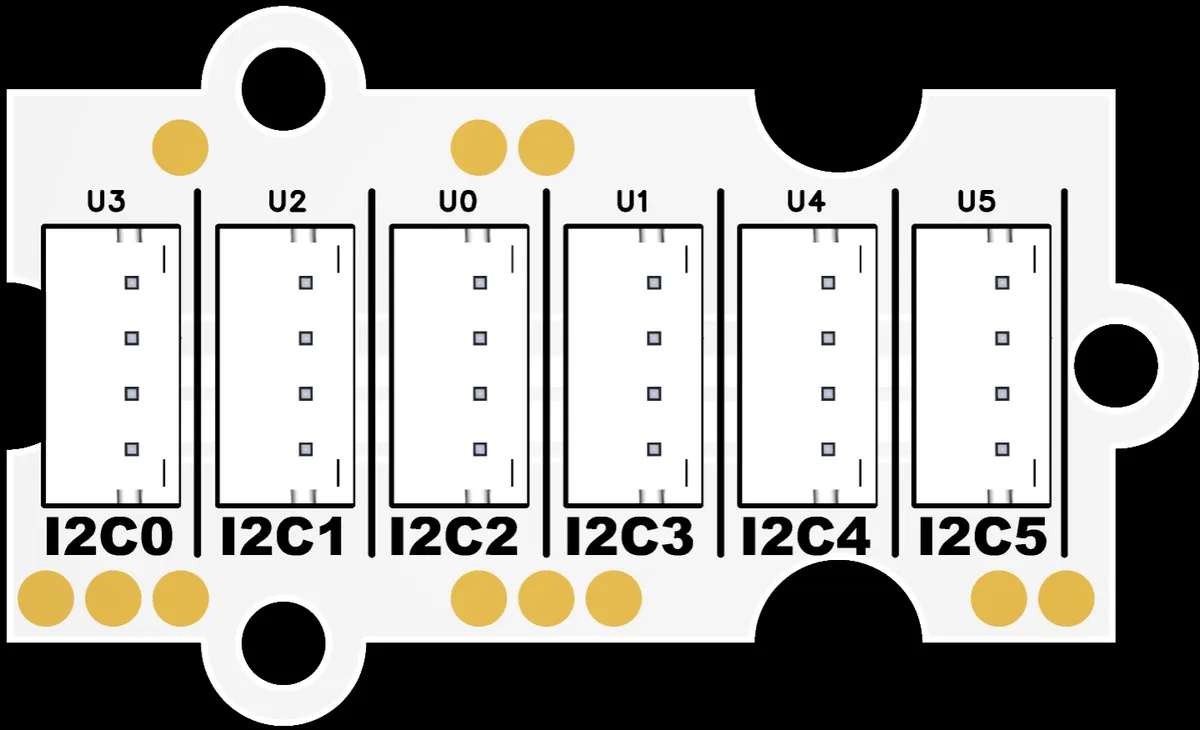
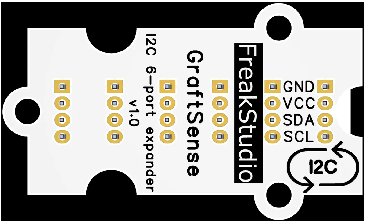
This module provides 6 I2C interfaces, covering channels from I2C0 to I2C5. It can provide independent communication links for 6 I2C devices simultaneously, supports parallel interaction among multiple devices, is suitable for the I2C expansion scenarios of multiple sensors and peripherals in maker development, can also meet the requirements of dense connection of I2C devices in fields such as industrial control, and provides an efficient solution for the I2C communication scalability of embedded systems.
3.3 Application Experiment
Here, we use the GraftPort-RP2040 development board for testing, and we will the 6-channel I2C direct connection expansion module to establish a communication connection with the main control unit via the I2C interface. Meanwhile, two types of functional modules are additionally connected to this expansion module:
- The 5-way key module based on PCF8574 is connected to the 6-channel I2C direct connection expansion module 's
I2C0 - 0.96-inch SSD1306-OLED module is connected to the 6-channel I2C direct connection expansion module 's
I2C1
Here, we first use the HY2.0-4P connection cable to connect the module to the GraftPort-RP2040 development board's I2C0 interface:
The module connections are shown in the following table:
development board pins | Module Pins | Description |
Pin 4 |
| I2C data transmission line, corresponding to |
Pin 5 |
| I2C clock signal line, corresponding to |
- | Mount any I2C device | The following uses a five-key module ( |
Here, we need to search for the relevant driver packages on uPyPI: https://upypi.net/zh/
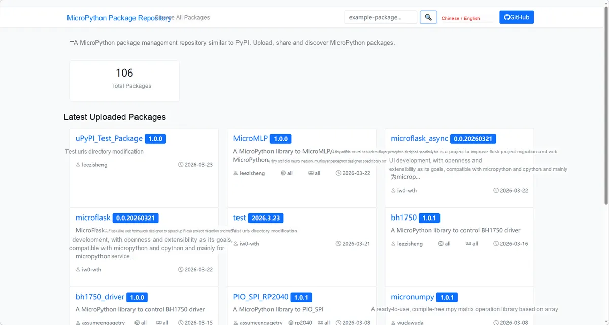
Enter mgx_driver to search, and the following will be displayed:
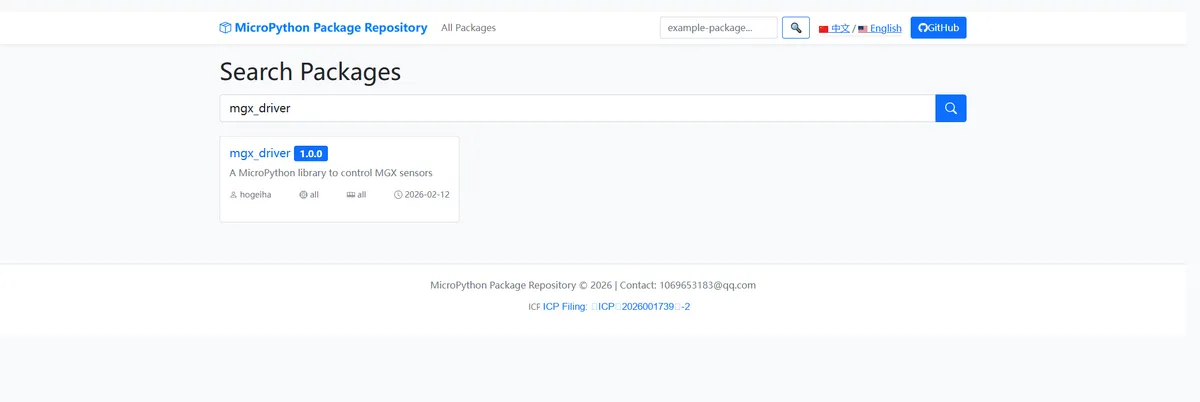
Click to copy the local installation command:
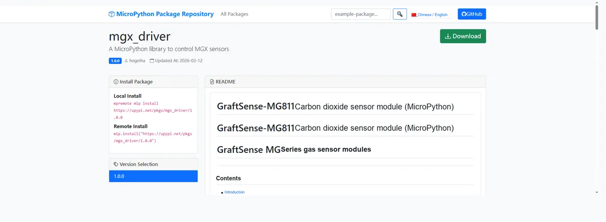
After importing the I2C Scan - MicroPython Test Code, copy the following main.py code into our project:
# Python env   : MicroPython v1.23.0 on Raspberry Pi Pico
# -*- coding: utf-8 -*-
# @Time    : 2025/1/19 AM 10:57
# @Author  : 侯钧瀚
# @File    : main.py
# @Description : I2C scan test program

# ======================================== Import Modules =========================================

from machine import Pin, I2C
# Import time-related modules
import time

# ======================================== Global Variables ============================================

# ======================================== Functions ============================================

# ======================================== Custom Classes ============================================

# ======================================== Initialization ==========================================

# Power-on delay of 3 s
time.sleep(3)
# Print debug message
print("FreakStudio: I2C Expansion Test")

# Initialize the I2C object
i2c = I2C(id=0, sda=Pin(4), scl=Pin(5), freq=400000)

# ========================================  Main Program  ===========================================

while True:
    # Scan and print the addresses on I2C
    print(i2c.scan())
    time.sleep(1)
Burn the code, open the terminal, and use the mpremote tool to connect to the main controller. The output is as follows:
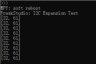
As you can see, we can scan all devices on a IIC bus and print out their addresses.
IV. Drivers
5. BOM & Recommended Alternative Parts
None.
VI. Revision History
Document Version | Revision Date | Modifier | Revised Content |
v1.0 | 2025-11-22 | Li Zisheng | Initialize Document |
v1.1 | 2025-12-29 | Li Zisheng | Added application experiments and production files |
v1.2 | 2025-12-31 | Sin Ruili | Create an open version of the document based on the internal document version v1.1. |
v1.3 | 2026-03-29 | Li Zisheng | Modified the application experiment section. |
VII. Relevant Materials
7.1 Chip Datasheet
None.
7.2 Unique Icons for PCB Silk Screen