Contents
- I. Module Introduction
- II. Introduction to Main Chips
- 2.1 Chip Overview
- 2.2 Pin Definition
- 2.3 Functional Block Diagram
- 2.4 Performance Parameters
- 2.5 Reference Circuit
- 2.6 Chip Configuration
- 2.7 Communication Interfaces and Related Protocols
- 2.8 PCB Routing Precautions
- III. Circuit Engineering
- 3.1 Circuit Source Engineering
- 3.2 Module Usage Instructions
- 3.3 Application Experiment
- IV. Drivers
- 5. BOM & Recommended Alternative Parts
- VI. Revision History
- VII. Relevant Materials
- 7.1 Chip Datasheet
- 7.2 Unique Icons for PCB Silk Screen
I. Module Introduction
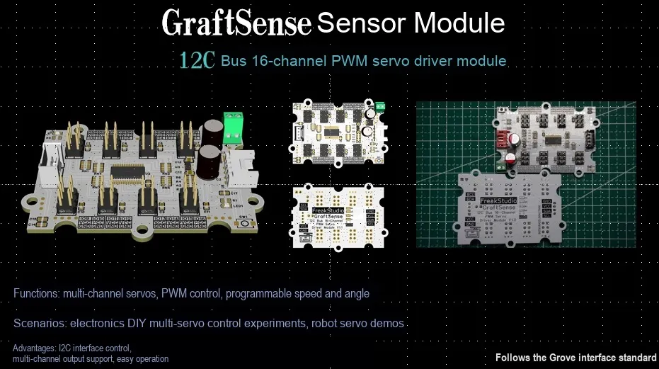
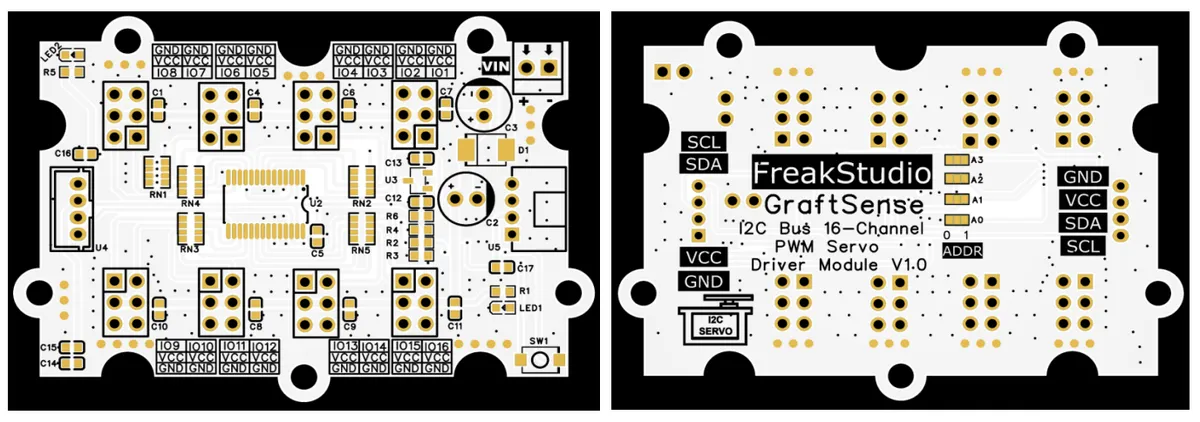
I2C bus 16-channel PWM servo drive module , the module has address selection control, pin limit viewership of protection and other designs, can output 16 PWM waveforms, the maximum output current is 5A, can drive multiple servos, and is also equipped with motor power supply input, multiple motor interfaces and power filtering, power lights and other circuits. Suitable for multi-servo control scenarios such as robots and automation equipment, it provides an efficient 16-channel PWM servo drive solution based on the I2C bus for the system.
II. Introduction to Main Chips
PCA9685PW, 118 is a 16-channel 12-bit high-precision PWM control chip. It communicates via the I2C bus, has a built-in 25MHz oscillator, the PWM frequency can be programmed and adjusted within the range of 24Hz to 1526Hz, the 12-bit resolution enables fine control of 4096 levels, and each channel supports a maximum output current of 25mA with independent configurability.This chip supports 64 different address configurations, allows up to 8 devices to be cascaded for channel expansion, features a standby current of less than 10μA with extremely low power consumption, and also boasts characteristics such as no output glitches upon power-up and hot-swappable functionality; it can not only drive LED s to achieve backlight dimming, but also precisely control steering gears, and is widely used in multi-channel PWM control scenarios such as robots, smart homes, and drones.
2.1 Chip Overview
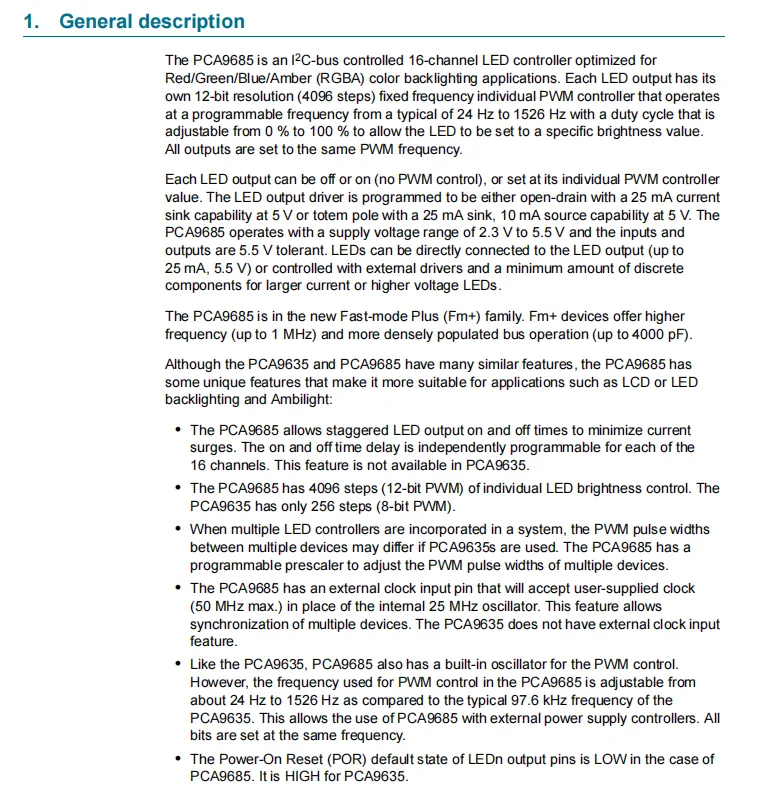
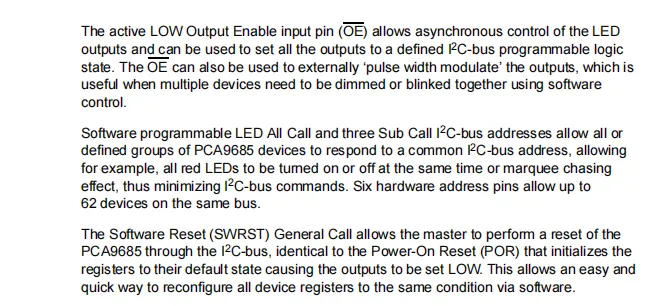
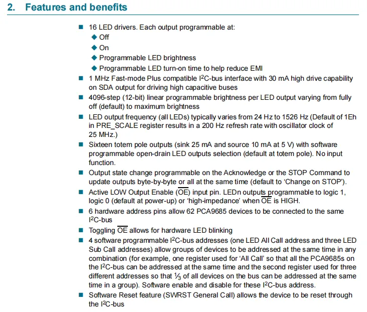
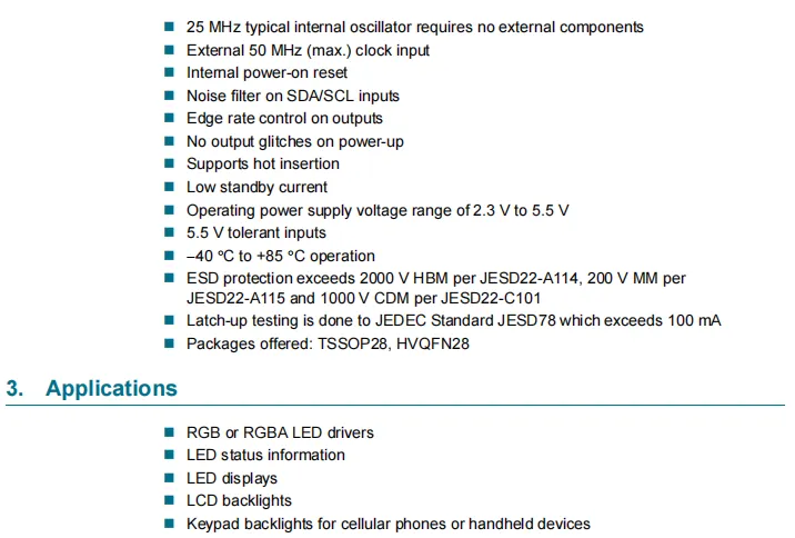
The PCA9685 is a 16-channel LED controller controlled via the I²C bus, designed primarily for RGB/RGBA backlighting applications. Each channel supports 12-bit PWM (4096-level brightness adjustment) with an adjustable PWM frequency ranging from 24Hz to 1526Hz. Its output can be configured in totem-pole or open-drain mode, enabling direct drive of low-current LEDs or connection to external drivers. It operates at a supply voltage of 2.3V to 5.5V and supports 1MHz high-speed I²C communication.It features independently programmable LED switching timing (to suppress current surges), external clock input (for multi-device synchronization) and other characteristics. With 6 address pins, up to 62 devices can be connected to the same bus, and it also supports functions such as All Call/Sub Call addresses (for multi-device synchronous control) and software reset, making it suitable for scenarios including RGB LED driving, LCD backlighting, and keypad backlighting of handheld devices.
2.2 Pin Definition
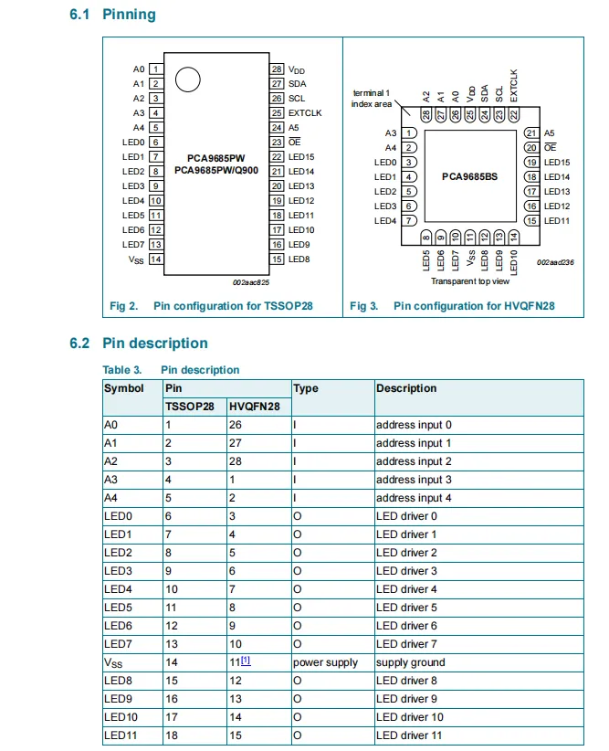
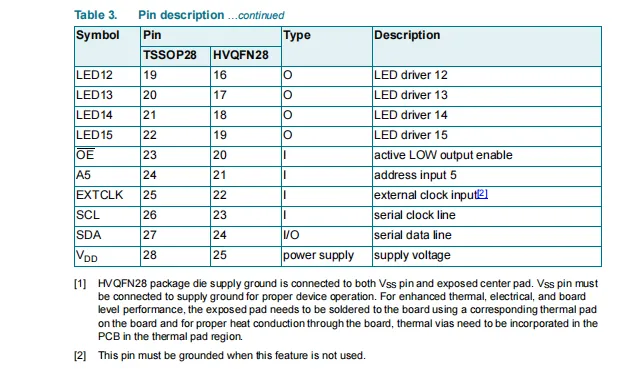
The pins of the PCA9685 fall into multiple categories: A0 to A5 are 6 input-type address pins (different packages correspond to different pin numbers), which are used to configure the I²C address to support up to 62 devices on the same bus; LED0 to LED15 are 16 output-type pins corresponding to 16 LED driving channels; among the power supply pins, Vss is the power ground (the HVQFN28 package requires connection to the exposed central pad for auxiliary heat dissipation) and Vdd is the power voltage input;The control and communication pins include the active-low output enable input pin OE, the external clock input pin EXTCLK (which must be grounded when not in use), as well as the SCL (serial clock) and SDA (serial data) I/O pins for I²C communication, which are used for interaction with the main controller.
2.3 Functional Block Diagram
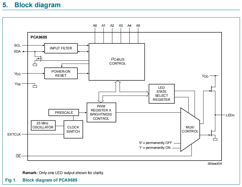
The functional block diagram of the PCA9685 centers on the I²C bus control module: this module configures the device address via the A0-A5 address pins, receives I²C communication signals of SCL/SDA through the input filter, and the power-on reset module ensures reset initialization upon power-up; for the clock section, either the 25MHz internal oscillator or the external EXTCLK input (via the clock switching module) can be selected, and the frequency is adjusted by the prescaler before being supplied to the PWM registers.The PWM registers are responsible for brightness control of each LED channel, the LED status selection registers configure the LED to be always off, always on or in PWM mode, the signal is finally output to the LEDn pins via the multiplexing control module, and the output enable OE also participates in controlling the output state, which collectively implements the 16-channel LED status and brightness management under I²C control.
2.4 Performance Parameters
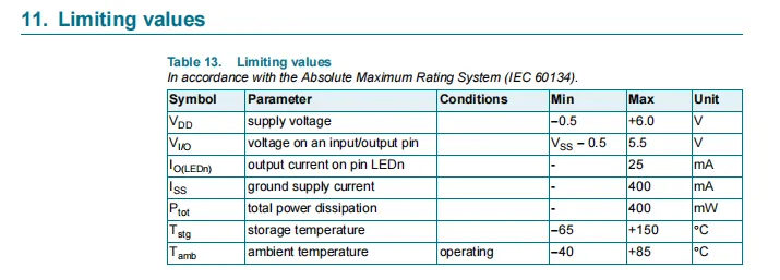
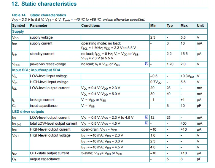
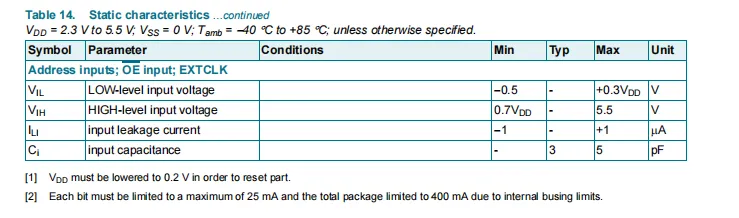
A brief introduction to the performance parameters of the PCA9685 is as follows:
Absolute Maximum Ratings: Power supply voltage range: -0.5V to + 6.0V; maximum voltage of input and output pins: 5.5V; maximum output current per individual LED channel: 25mA; total output current for all LEDs: 400mA; total power consumption: ≤400mW; operating ambient temperature range: -40℃ to + 85℃.
In terms of static characteristics, the operating power supply voltage ranges from 2.3 V to 5.5 V, the typical operating current is 6 mA (maximum 10 mA), and the standby current is only 2.2 μA; the high and low level input requirements for the I²C interface shall meet ≥0.7VDD and ≤0.3VDD respectively;For the LED driver, the single-channel low-level output current is at least 12mA (typically 25mA) within the range of 2.3V to 4.5V, the total low-level output current is limited to 400mA, the high-level output current in open-drain mode is only ±10μA, and the corresponding high-level output voltage ranges from 1.6V (at a supply voltage of 2.3V) to 4.0V (at a supply voltage of 4.5V).
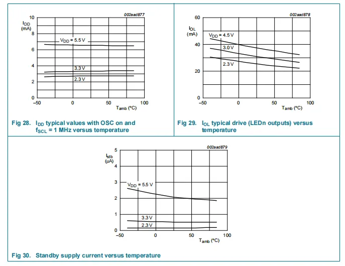
This set of diagrams illustrates the variation characteristics of different electrical parameters of the PCA9685 with temperature:
- Fig. 28 presents the temperature characteristics of the operating current I_DD (with the oscillator enabled and SCL = 1 MHz): under different supply voltages (2.3 V / 3.3 V / 5.5 V), I_DD exhibits minimal variation with temperature, and a higher supply voltage corresponds to a slightly larger I_DD value.
- Fig 29 shows the temperature characteristics of the LED output drive current I_O: at different supply voltages (2.3V/3.0V/4.5V), I_O shows a slight downward trend as temperature rises, and a higher supply voltage corresponds to a higher I_O value.
- Fig. 30 illustrates the temperature characteristics of the standby current: under different supply voltages (2.3V/3.3V/5.5V), the standby current (in the μA range) increases slightly as the temperature rises, and a higher supply voltage corresponds to a slightly larger standby current value.
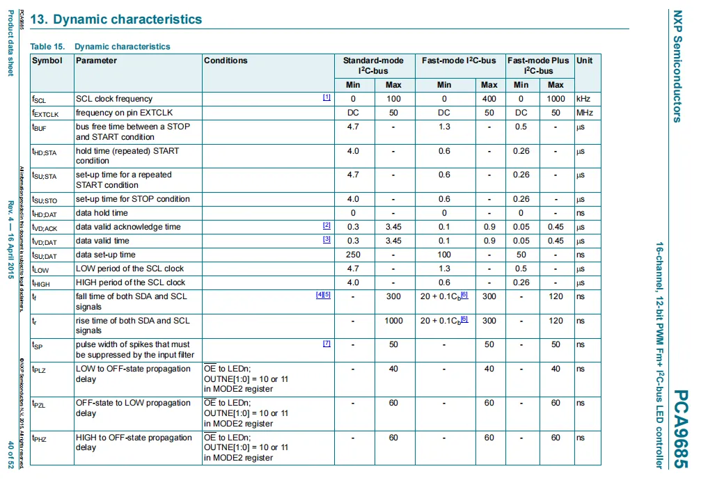
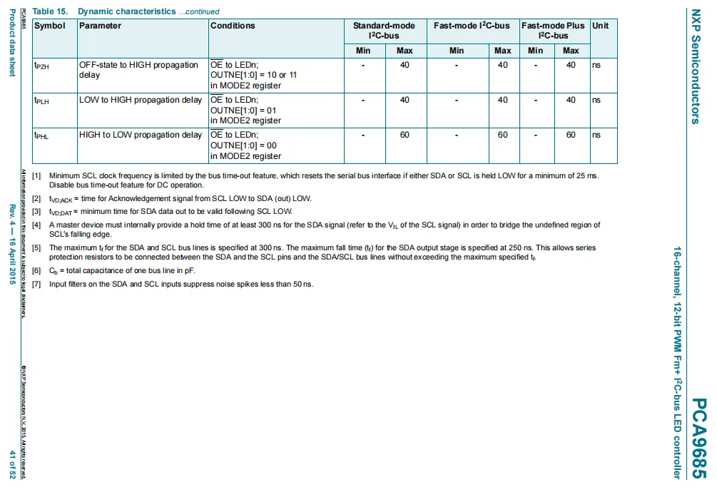
The dynamic characteristics of the PCA9685 center on the I²C bus timing and clock parameters, covering three I²C modes: Standard-mode, Fast-mode, and Fast-mode Plus. The maximum SCL clock frequency limits for the three modes are 100kHz, 400kHz, and 1000kHz respectively, and the EXTCLK pin supports a maximum input frequency of 50MHz.It covers timing parameters including the idle time of the I²C bus, the setup/hold time for START/STOP conditions, and the data valid time (these parameters decrease as the bus speed increases), as well as the SCL clock cycle, the rise and fall times of SDA/SCL, and the state propagation delay from OE to LEDn, which reflects the timing compatibility and signal response characteristics of the chip under different communication rates.
2.5 Reference Circuit
The following is the schematic diagram of the reference application circuit provided in the datasheet:
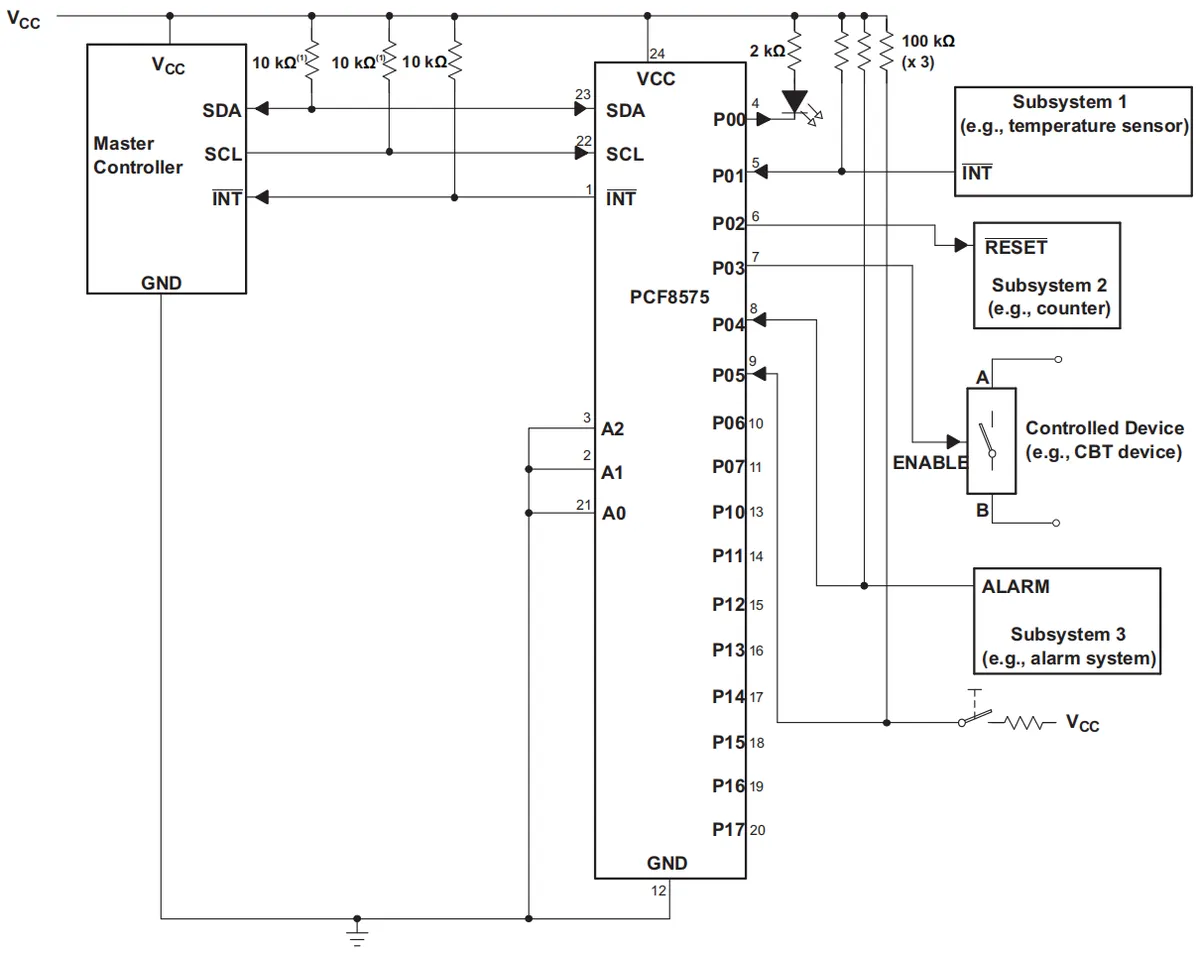
Among them, the SDA, SCL and INT pins require external pull-up resistors; A2, A1 and A0 are all connected to GND, and the I2C communication address is 0100000. Ports P0, P2 and P3 are configured as outputs, while ports P1, P4 and P5 are configured as inputs. Meanwhile, in the VCC power supply section, two capacitors need to be connected in parallel to filter noise from the power supply (not shown in the figure).
2.6 Chip Configuration
None.
2.7 Communication Interfaces and Related Protocols
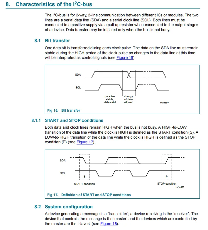
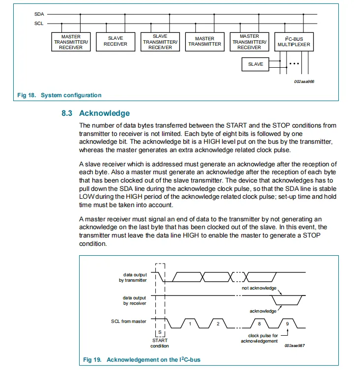
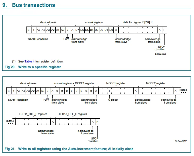
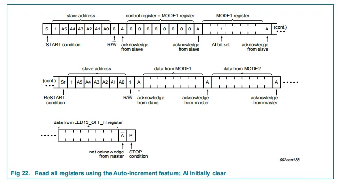
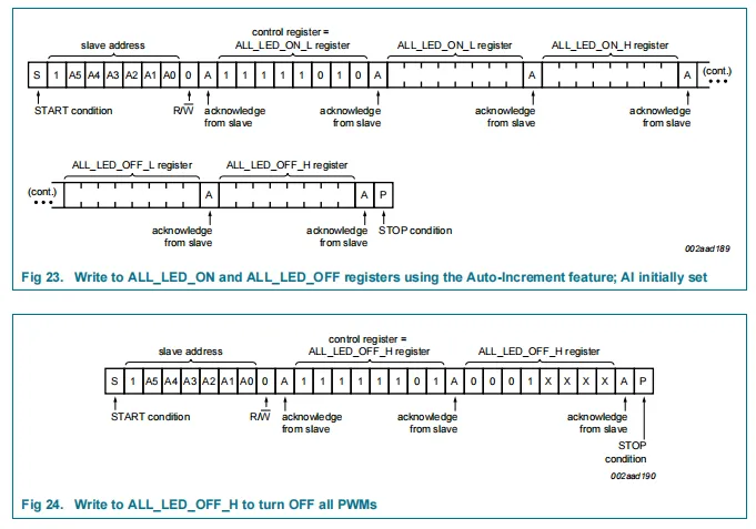
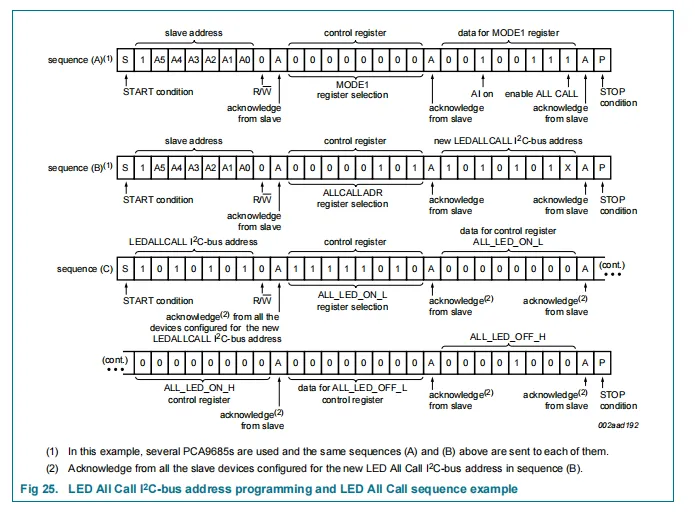
I²C is a two-wire bidirectional communication protocol based on SDA (Serial Data) and SCL (Serial Clock), requiring pull-down resistors on the bus; both SDA and SCL remain at a high level when the bus is idle. During bit transmission, one bit is transferred per clock pulse, and SDA must remain stable while SCL is high. Bus transactions are controlled via the START condition, defined by a high-to-low transition of SDA when SCL is high, and the STOP condition, defined by a low-to-high transition of SDA under the same SCL high state. Each data byte must be followed by an acknowledge bit (the receiver pulls SDA low to acknowledge, and no acknowledge is required for the final byte).
For the PCA9685, its I²C communication consists of write operations (sending the slave address + write bit and control register address after a START condition, followed by data, supporting auto-increment for writing to multiple registers) and read operations (first writing the register address, then sending a RESTART condition followed by the slave address + read bit to read data). It also supports batch control of multiple PCA9685 devices via All Call address programming to implement functions such as register configuration and LED status setting.
2.8 PCB Routing Precautions
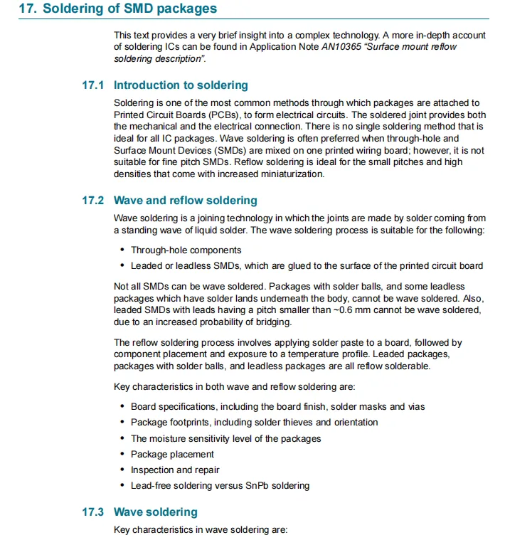
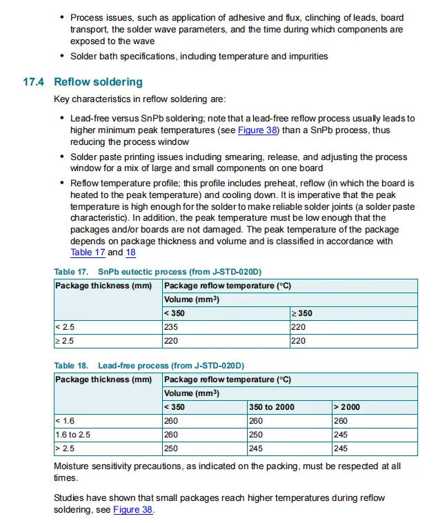
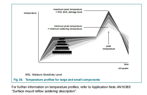
This section describes the soldering instructions for SMD packaged devices such as the PCA9685, focusing on two processes: wave soldering and reflow soldering. Wave soldering is suitable for through-hole devices as well as leaded and leadless surface-mount SMDs, but it is not applicable to SMDs with a pin pitch < 0.6mm or those with pads on the bottom side.Reflow soldering is more suitable for fine-pitch, highly integrated SMDs (including packages with solder balls and leadless packages). It should be noted that the peak reflow temperature of lead-free processes is higher than that of leaded processes. Meanwhile, solder paste printing and the reflow temperature curve (which must take both the solder paste characteristics and component heat resistance into account) shall be controlled. Different package thicknesses/volumes correspond to different reflow temperatures, and smaller packages require higher temperatures during reflow. In addition, the moisture sensitivity level requirements of components must be complied with.
III. Circuit Engineering
3.1 Circuit Source Engineering
To obtain the circuit source project, please follow the official account [Freak Embedded]
3.2 Module Usage Instructions
SCH_Schematic1_I2C Bus 16-Channel PWM Servo Driver Module-V1.0.0_2025-11-18.pdf 2.4 MB
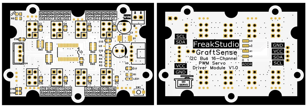
This module provides an I2C communication interface: it supports standard I2C communication rates, allows flexible configuration of multiple sets of I2C addresses via the A0, A1 and A2 pins to avoid address conflicts among bus devices, and is compatible with 3.3V/5V system logic levels to adapt to different main control devices;This interface can be used to control the output of 16 independent PWM waveforms. Combined with the module's power circuit, it supports stable servo drive current, and is suitable for multi-servo coordination scenarios such as robot joint control and actuator driving of automated equipment, providing the system with a compact and efficient 16-channel PWM servo control solution based on the I2C bus.
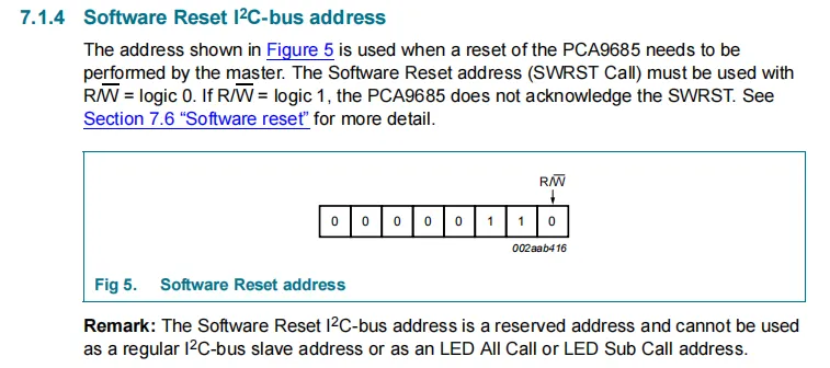
PCA9685PW The specific selection method for its I2C address is as follows:
Standard slave address: Based on the 7-bit base address 0b1000000 (corresponding to 0x40), the lower 6 bits are determined by the level (pull-up/pull-down) configuration of pins A0 to A5. By adjusting the level of these 6 pins, different addresses in the range of 0x40 to 0x7F can be selected for multi-device mounting on the I2C bus. Here, we only enable the four address selection bits from A0 to A3, whose positions on the physical device are as follows:
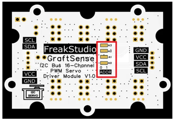
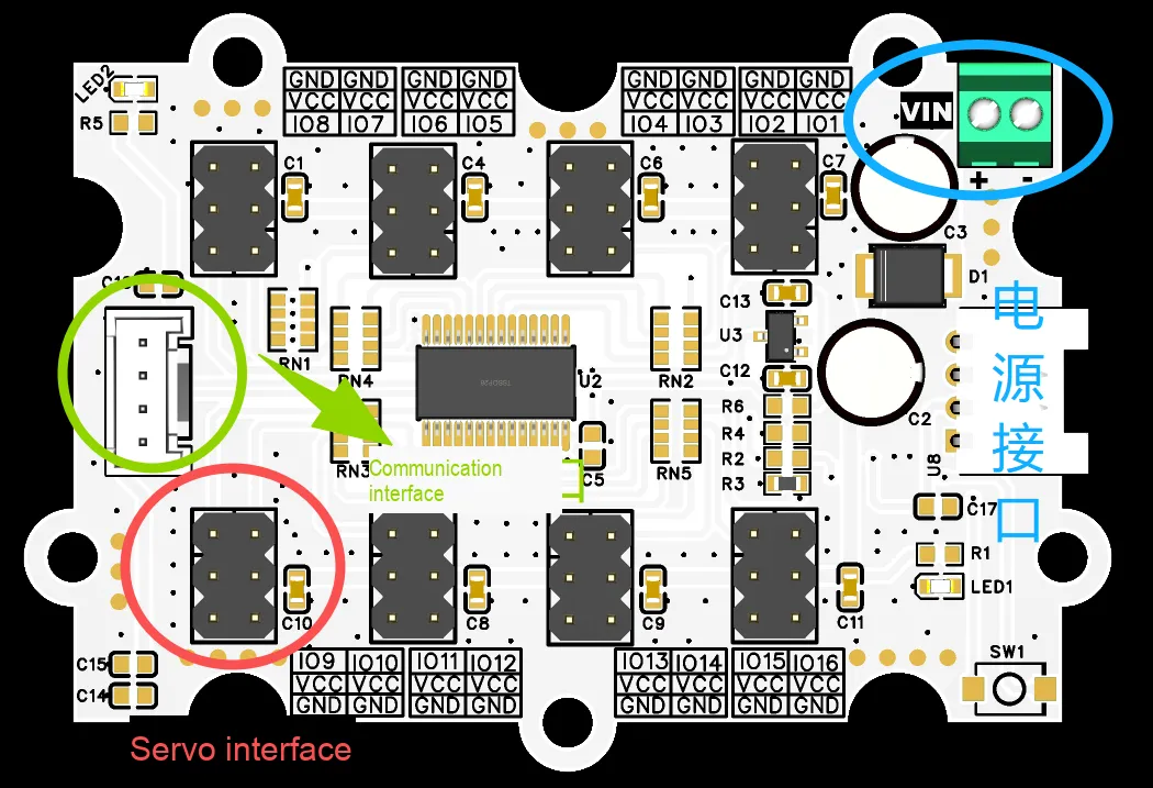
It should be noted here that in use, we need to use the VIN interface to connect to an external 5V power supply; the servo connection and communication connection are shown in the following figure:
3.3 Application Experiment
Here, we use the GraftPort-RP2040 development board for testing, and the I2C bus 16-channel PWM servo driver module uses the I2C interface to communicate with the main controller.
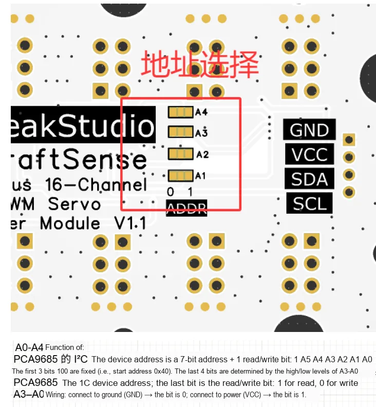
Here, we need to set the address bits in advance by soldering two short-circuit points:(the selected address is 0x4A)
Here, we first use the HY2.0-4P connection cable to connect the module to the GraftPort-RP2040 development board's I2C0 interface:
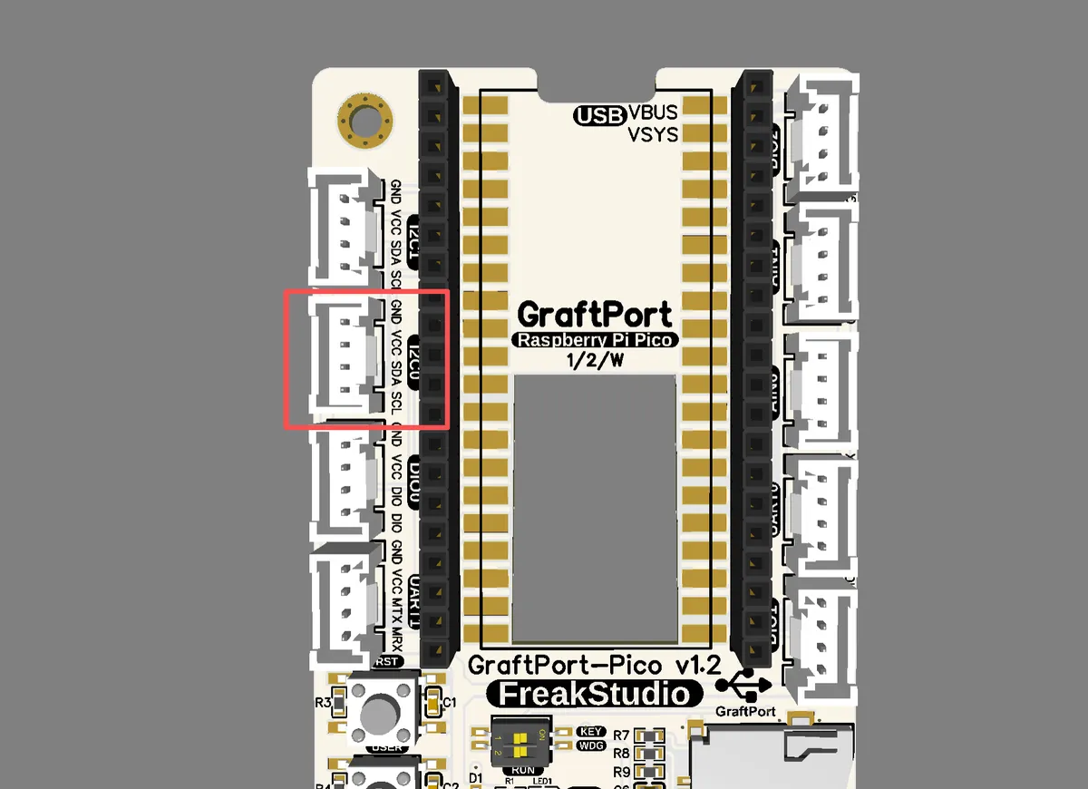
The module connections are shown in the following table:
connection object | development board pins | Module Pins | Description |
Development Board and Module ( | Pin 4 |
| I2C data transmission line, corresponding to |
Development Board and Module ( | Pin 5 |
| I2C clock signal line, corresponding to |
Servo Module and Servo | - |
|
|
Servo Module and Servo | - |
|
|
Here, we use the LM2596S adjustable power supply module to provide external 5V power supply for the I2C bus 16-channel PWM servo driver module (the servos connected to this module can only operate with external power supply).
Here, we need to search for the relevant driver packages on uPyPI: https://upypi.net/zh/
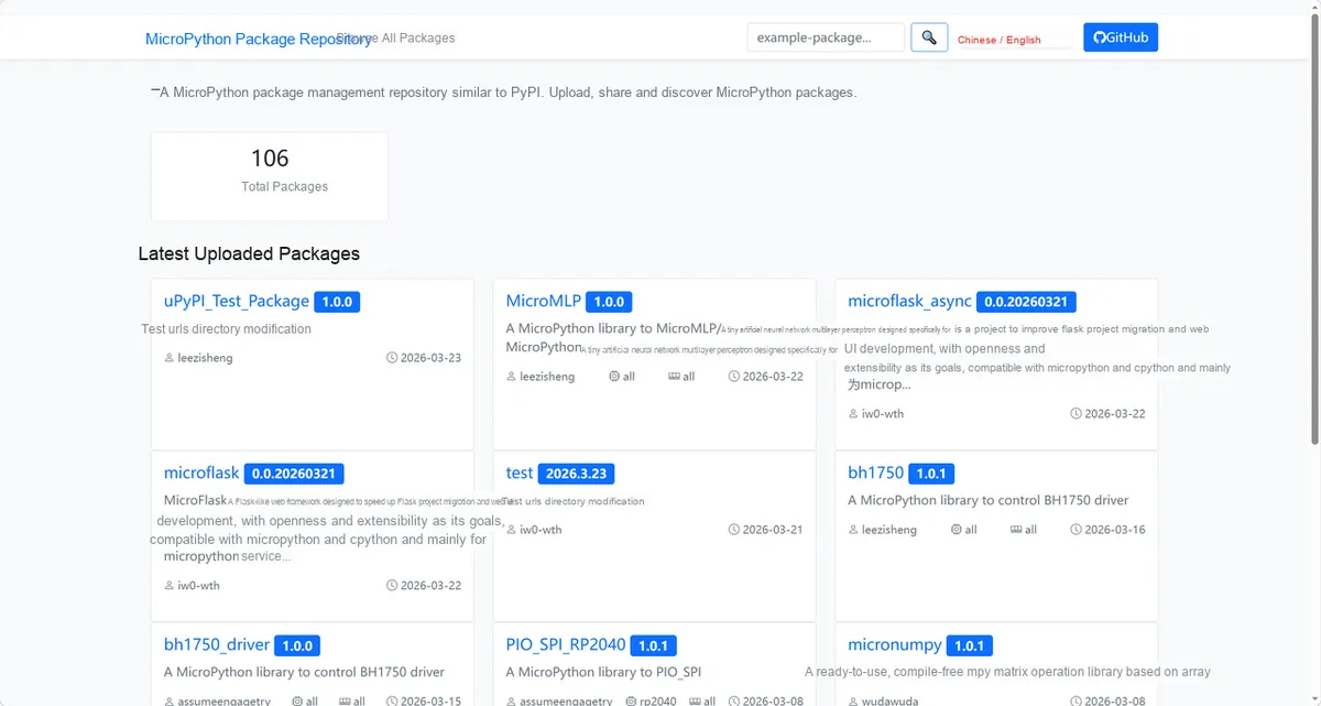
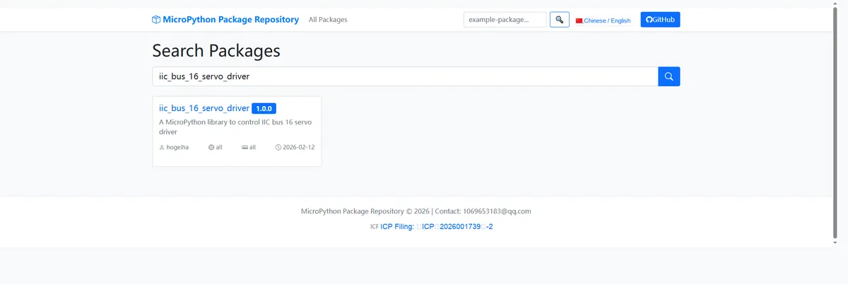
Enter iic_bus_16_servo_driver to search, and the following will be displayed:
Click to copy the local installation command:
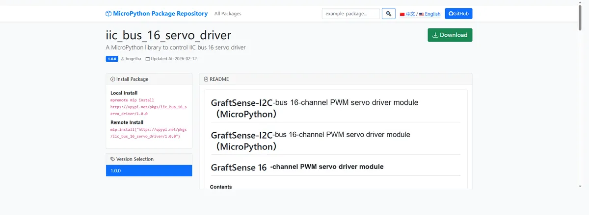
Here, we can import the module driver library code via the mip tool. Below are the usage commands for the mpremote tool:
mpremote mip install github:FreakStudioCN/GraftSense-Drivers-MicroPython/motor_drivers/iic_bus_16_servo_driverImport the 16-channel PWM servo driver module via I2C bus - MicroPython driver code, then copy the following main.py code into our project:
# Python env   : MicroPython v1.23.0
# -*- coding: utf-8 -*-
# @Time    : 2025/09/04 10:00
# @Author  : 侯钧瀚
# @File    : main.py
# @Description : PCA9685 16-channel PWM driver board example program

# ======================================== Import Modules =========================================

# Import the time module
import time
# Import MicroPython standard library modules
from machine import Pin, I2C
# Import the bus servo controller module
from bus_servo import BusPWMServoController
# Import the PCA9685 module
from pca9685 import PCA9685

# ======================================== Global Variables ============================================

# Automatically scan for the PCA9685 address (0x40~0x4F)
addr = 0x40

# ======================================== Functions ============================================

# ======================================== Custom Classes ============================================

# ======================================== Initialization ==========================================

# Power-on delay of 3 s
time.sleep(3)
# Print debug message
print("FreakStudio: Using PCA9685 to control the angles of two servos")
# Create a hardware I2C instance using the I2C0 peripheral, with a clock frequency of 400KHz, SDA pin 4, and SCL pin 5
i2c = I2C(id=0, sda=Pin(4), scl=Pin(5), freq=400000)

# Start scanning for devices on the I2C bus and return a list of slave addresses
devices_list = i2c.scan()
print('START I2C SCANNER')

# If devices_list is empty, no device is connected to the I2C bus
if len(devices_list) == 0:
    print("No i2c device !")
# If not empty, print the slave device addresses
else:
    print('i2c devices found:', len(devices_list))
    # Iterate over the slave device address list
    for device in devices_list:
        # Check whether the device address is the PCF8575 address
        if device >= 0x40 and device <= 0x4F:
            print("I2C hexadecimal address: ", hex(device))
pca = PCA9685(i2c,  address = device)

# Create the controller (50Hz is commonly used for servos)
srv = BusPWMServoController(pca, freq=50)

# Bind servo channels

# Channel 0: 180° servo, standard 500~2500us, 1500us is neutral
srv.attach_servo(0, BusPWMServoController.SERVO_180, min_us=500, max_us=2500, neutral_us=1500)
# Channel 1: 180° servo, standard 500~2500us, 1500us is neutral
srv.attach_servo(1, BusPWMServoController.SERVO_180, min_us=500, max_us=2500, neutral_us=1500)
# Channel 2: 180° servo, standard 500~2500us, 1500us is neutral
srv.attach_servo(2, BusPWMServoController.SERVO_180, min_us=500, max_us=2500, neutral_us=1500)
# Channel 3: 180° servo, standard 500~2500us, 1500us is neutral
srv.attach_servo(3, BusPWMServoController.SERVO_180, min_us=500, max_us=2500, neutral_us=1500)

# Set the 360° servo channels
# Channel 1: 360° continuous servo, with its own stop point near 1500us; use reversed=True for reverse direction if needed
srv.attach_servo(4, BusPWMServoController.SERVO_360, min_us=1000, max_us=2000, neutral_us=1500)
# Channel 1: 360° continuous servo, with its own stop point near 1500us; use reversed=True for reverse direction if needed
srv.attach_servo(5, BusPWMServoController.SERVO_360, min_us=1000, max_us=2000, neutral_us=1500)

# ========================================  Main Program  ===========================================

# Demonstrate 180° angle control
# Turn to 0°
srv.set_angle(0, 0.0)
# Turn to 0°
srv.set_angle(1, 0.0)
# Turn to 0°
srv.set_angle(2, 0.0)
# Turn to 0°
srv.set_angle(3, 0.0)
time.sleep(1)
# Smoothly turn to 90° at about 120°/s
srv.set_angle(0, 90.0, speed_deg_per_s=120)
# Smoothly turn to 90° at about 120°/s
srv.set_angle(1, 90.0, speed_deg_per_s=120)
# Smoothly turn to 90° at about 120°/s
srv.set_angle(2, 90.0, speed_deg_per_s=120)
# Smoothly turn to 90° at about 120°/s
srv.set_angle(3, 90.0, speed_deg_per_s=120)
time.sleep(1)
# Smoothly turn to 180°
srv.set_angle(0, 180.0, speed_deg_per_s=180)
# Smoothly turn to 180°
srv.set_angle(1, 180.0, speed_deg_per_s=180)
# Smoothly turn to 180°
srv.set_angle(2, 180.0, speed_deg_per_s=180)
# Smoothly turn to 180°
srv.set_angle(3, 180.0, speed_deg_per_s=180)
time.sleep(1)
# Return to center or stop
srv.stop(0)

# Demonstrate 360° speed control
# Clockwise at medium speed
srv.set_speed(4, +0.6)
# Clockwise at medium speed
srv.set_speed(5, +0.6)
time.sleep(20)
# Reverse at medium speed
srv.set_speed(4, -0.6)
# Reverse at medium speed
srv.set_speed(5, -0.6)
time.sleep(20)
# Channel 4 returns to center or stops
srv.stop(4)
# Channel 5 returns to center or stops
srv.stop(5)
# Return to center or stop

time.sleep(0.5)
# Turn off output and unbind
srv.detach_servo(0)
# Turn off output and unbind
srv.detach_servo(1)
# Turn off output and unbind
srv.detach_servo(2)
# Turn off output and unbind
srv.detach_servo(3)
# Turn off output and unbind
srv.detach_servo(4)
# Turn off output and unbind
srv.detach_servo(5)
To flash the code, open a terminal and use the mpremote tool to connect to the main controller; the output is as follows:
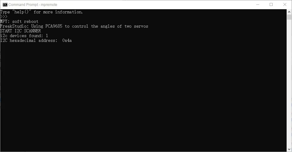
It can be seen that we can currently read the I2C address of the module normally, and we can observe that the movement of the servo is consistent with the preset effect in the code.
IV. Drivers
iic_bus_16_servo_driver.zip 13 KB
5. BOM & Recommended Alternative Parts
None.
VI. Revision History
Document Version | Revision Date | Modifier | Revised Content |
v1.0 | 2025-11-18 | Xing Gao | Initialize Document |
v1.1 | 2025-12-29 | Li Zisheng | Added application experiments and production files |
v1.2 | 2025-12-31 | Sin Ruili | Create an open version of the document based on the internal document version v1.1. |
v1.3 | 2026-03-29 | Sin Ruili | Modified the application experiment section |
VII. Relevant Materials
7.1 Chip Datasheet
PCA9685.pdf 399 KB
7.2 Unique Icons for PCB Silk Screen