Contents
- I. Module Introduction
- II. Introduction to Main Chips
- 2.1 Chip Overview
- 2.2 Pin Definition
- 2.3 Functional Block Diagram
- 2.4 Performance Parameters
- 2.5 Reference Circuit
- 2.6 Chip Configuration
- 2.7 Communication Interfaces and Related Protocols
- 2.8 PCB Routing Precautions
- III. Instructions for Circuit Engineering and Module Usage
- 3.1 Circuit Source Engineering
- 3.2 Module Usage Instructions
- 3.3 Application Experiment
- IV. Drivers
- 5. BOM & Recommended Alternative Parts
- VI. Revision History
- VII. Relevant Materials
- 7.1 Chip Datasheet
- 7.2 Unique Icons for PCB Silk Screen
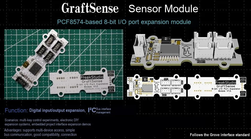
I. Module Introduction
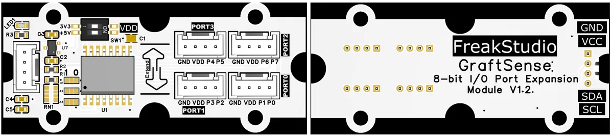
8-bit IO Port Expansion Module Based on PCF8574 with its core adopting the PCF8574T/TR chip, which realizes the expansion of 8-channel IIC communication (with onboard IIC pull-up circuit) to expand 8-channel IO (P0 - P7), and the corresponding PORT0 - PORT3 interfaces are used for connecting peripherals/sensors;This module integrates a 5V-to-3.3V power supply circuit, and allows configuration via jumper caps for A0 / A1 / A2 to select chip addresses ranging from 0x20 to 0x27. It is also equipped with a power selection switch and a power indicator. Note that its IO pins adopt an open-drain design, so an external triode / MOSFET is required for driving heavy loads. It is suitable for IO expansion scenarios of devices such as microcontrollers.
II. Introduction to Main Chips
2.1 Chip Overview
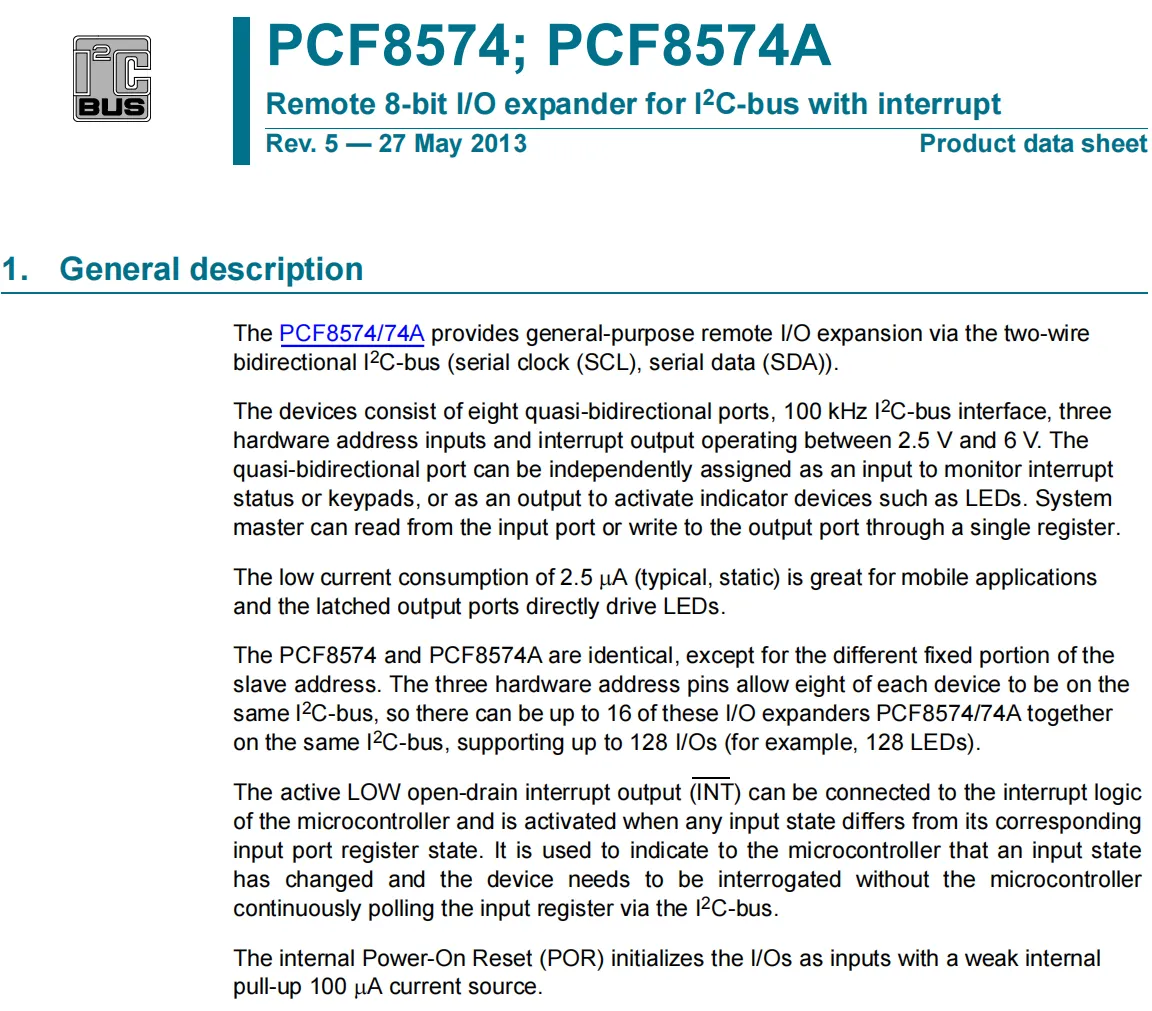
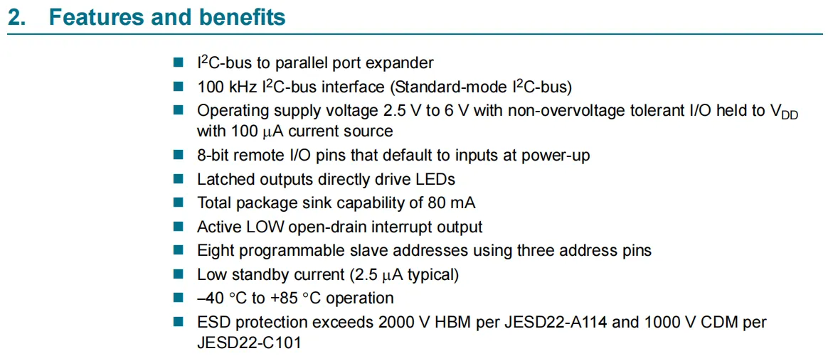
PCF8574 is an 8-bit remote IO expander for I ² C bus (supports interrupt function), which realizes the expansion of 8 quasi-bidirectional IO through SCL and SDA , with a working voltage of 2.5V-6V and a static power consumption of only 2.5μA (typical value), suitable for mobile scenarios;It supports 100kHz I²C communication, with 3 address pins configurable for 8 slave addresses (PCF8574 and PCF8574A only differ in the fixed address segment; up to 16 chips can be compatible on the same bus to expand 128 I/O channels). IO pins default to input (with weak pull-up) on power-up, the latched output can directly drive LED (total sink current 80mA). It also features a low-level open-drain interrupt output (to avoid host polling IO status), operates within the temperature range of -40°C to + 85°C, and has excellent ESD protection capability.
2.2 Pin Definition
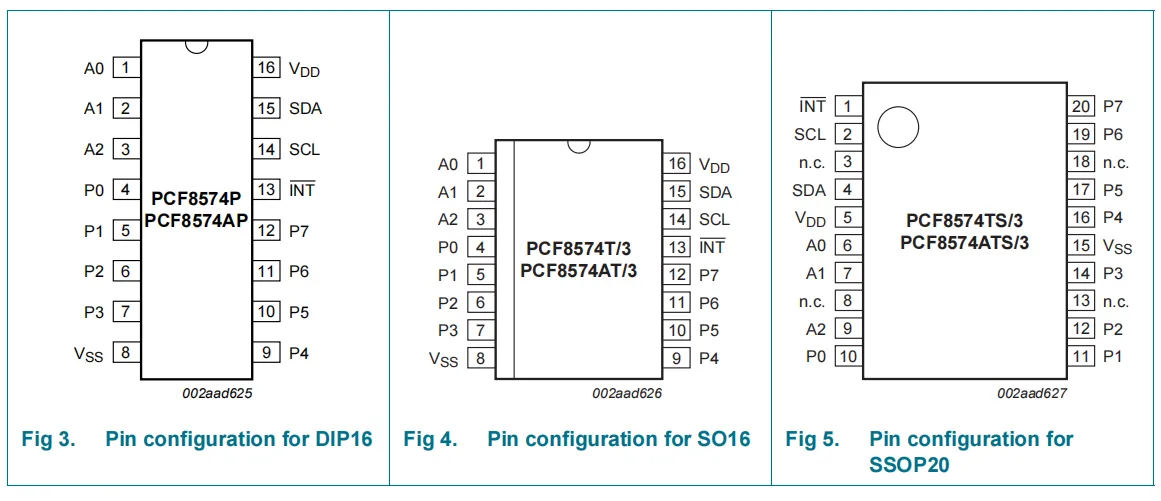
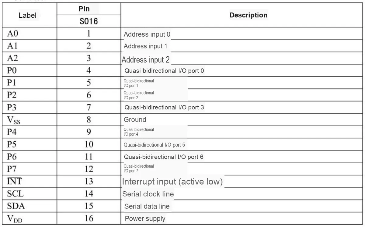
2.3 Functional Block Diagram
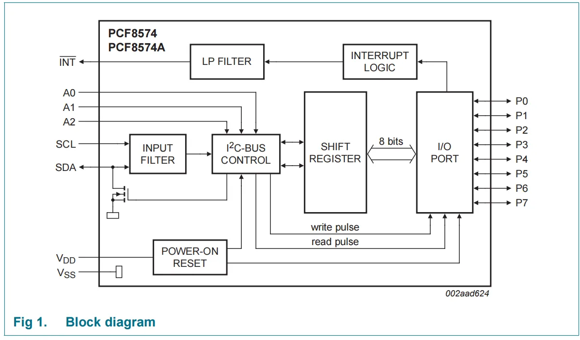
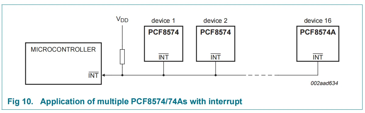
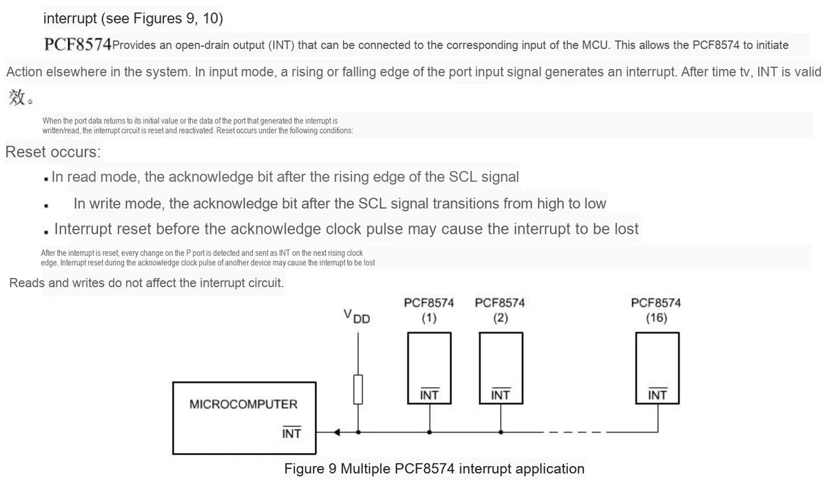
This PCF8574 block diagram illustrates its core working architecture: upon power-up, the " POWER-ON RESET " initializes the IO ports to input mode;I²C communication SCL / SDA signals are first processed by the "INPUT FILTER", then the "I²C bus control module" parses commands and addresses (pins INPUT FILTER provide the slave address), and the "shift register" realizes the temporary storage and transmission of 8-bit data: the write pulse sends data from the shift register to the "8-bit I²C IO port"(for output), while the read pulse posts back the input state of the IO port to the shift register (for the master to read);A0 / A1 / A2 IO Meanwhile, the "interrupt logic (INTERRUPT LOGIC)" monitors the status changes of the IO ports, and outputs a low-level INT interrupt signal via the low-pass filter (LP FILTER), which replaces host polling to notify the IO status update. All modules cooperate to complete the expansion control from I²C to 8-channel IO.
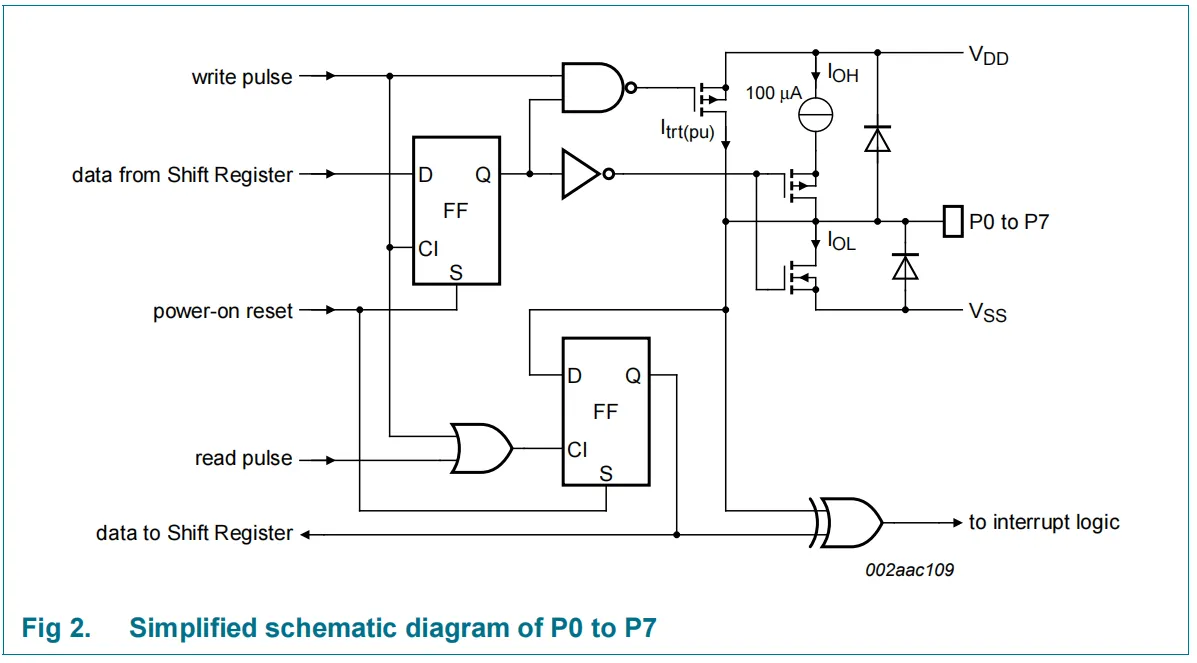
This PCF8574 's P0 - P7 IO ports adopt a quasi-bidirectional structure, and the circuit consists of latch, driver and status monitoring modules: the data of the shift register is latched by a D flip-flop, and then controls the MOS transistors and the 100μA pull-up current source at the output terminal through a logic circuit;In terms of output driving capability, the typical value of pull-up current (Iₒₕ) is only 100μA (weak driving capability), and it mainly relies on sink current (Iₒₗ) to drive loads. In addition, the upper limit of the sink current for the total chip package is 80mA (the sum of all IO ports), so this IO port can directly drive small loads such as LED s (i. e., it is recommended that the positive terminal of loads like LEDs be connected to VCC, and the negative terminal be connected to the IO port); for driving high-current loads, an external triode / MOSFET is required;Meanwhile, IO port status will be captured by the sampling trigger to trigger the interrupt logic, and the power-on reset will also initialize IO to the input mode.
2.4 Performance Parameters
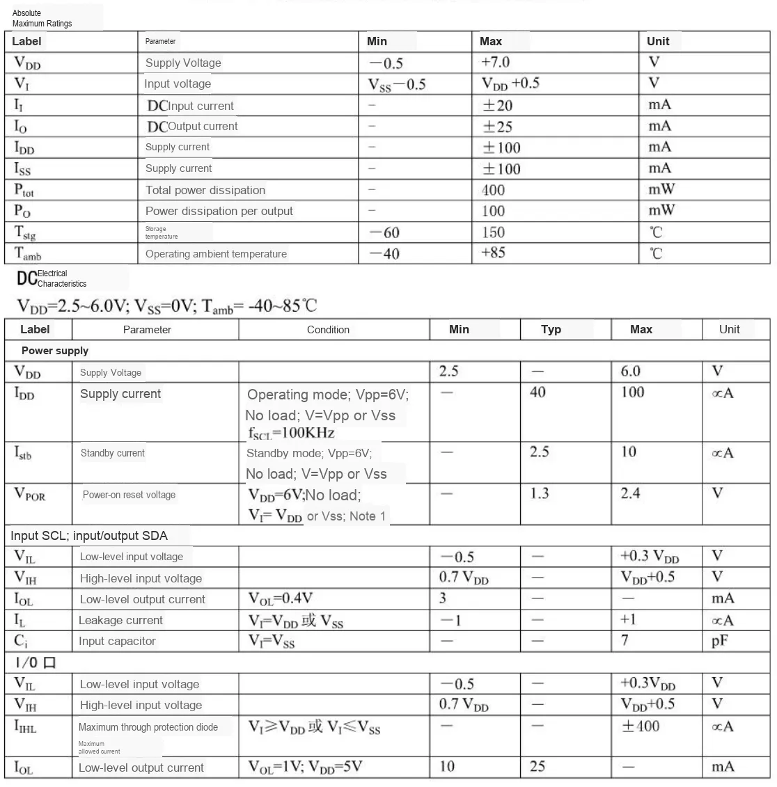
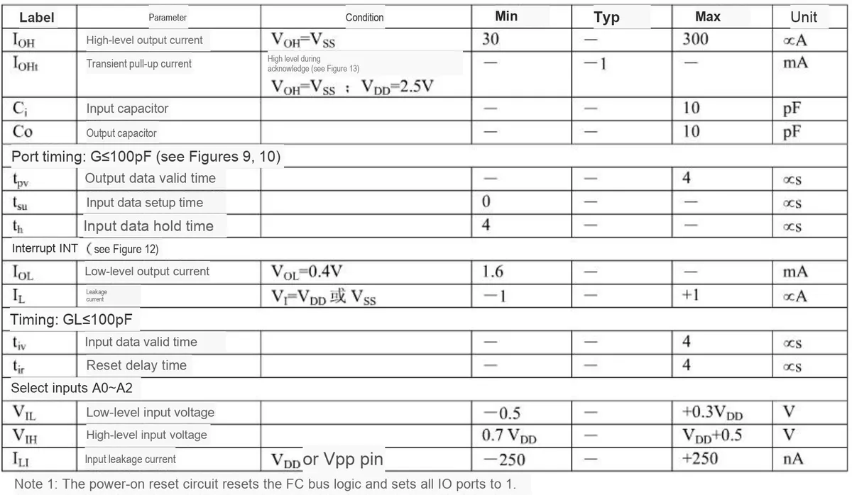
In the circuit design of PCF8574, these key parameters require focused attention:
- First of all, regarding power supply parameters, the
VDDpower supply voltage has a Scope of Work of 2.5~6.0V (the limit shall not exceed 7.0V). Meanwhile, attention shall be paid to the power-on reset voltageVPOR(typically 1.3V) to ensure the power supply is stable enough to meet the reset requirements; - Next comes IO driving capability: the high-level output current
Iₒₕis only up to 300μA (extremely weak driving capability), while the low-level output currentIₒₗhas a minimum value of 10mA (typically 25mA); in addition, the total sink current of the chip is limited, so the sink current mode shall be prioritized for load driving, and an external triode /MOSFETis required for large loads; - It is also necessary to match the voltage level standards: the high and low levels of input/output must meet the thresholds of
0.3VDD(low) and0.7VDD(high) to avoid level incompatibility; - In addition, it is necessary to control the input/output capacitance (
Ci/Co, max. 10 pF) to ensure the signal integrity of theI²Cbus timing. - Finally, note the leakage current parameters (the input /
IOport leakage currents are all at the μA/nA level) and the input leakage current of the address pins (±250nA) to avoid reliability issues with weak pull levels.
2.5 Reference Circuit
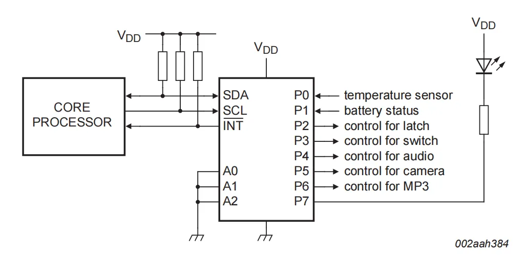
This scenario is a typical application of PCF8574 as an 8-bit bidirectional IO expander: it connects to the core processor via the I²C (SDA / SCL) bus and the INT interrupt line, where P0 and P1 are configured as inputs (connected to a temperature sensor and battery status detector respectively), and P2 to P7 are configured as outputs (controlling latches, switches, audio-visual peripherals, etc. , with P7 also driving an LED). Note the following during configuration: during the write operation phase, the input pins (P0 / P1) must be written to 1 to ensure that external devices have full control over the inputs;The output ports (P2 – P7) can be written to set the target high or low level; if the internal 10μA pull-up current is insufficient, an external pull-up resistor needs to be added to the port. A read operation simultaneously acquires the level of the external device at the input port and the logic level previously written to the output port. Additionally, the PCF8574 's INT interrupt line can be connected to the processor' s interrupt logic: when data on the IO port changes, it can actively send an interrupt to notify the processor without relying on I²C bus polling.
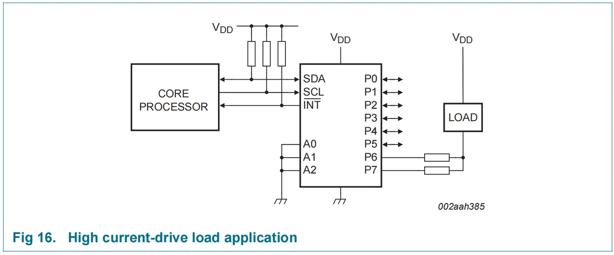
This scenario describes the high-current load driving application of PCF8574: its GPIO can provide a sink current of at least 10mA per single pin at 5V; for higher driving capability, multiple port pins can be connected in parallel (e. g., 2 pins in parallel can sink 20mA, up to 5 pins in parallel to reach the device's total recommended upper limit of 80mA), but the parallel-connected pins must be switched on/off synchronously. Meanwhile, each parallel-connected pin requires an independent current-limiting resistor (as shown in the figure, P6 and P7 are each connected to a resistor before being connected in parallel to drive the LOAD load), to prevent device damage caused by asynchronous switching of the pins.In the circuit, PCF8574 still communicates with the core processor via SDA / SCL, the INT pin transmits the interrupt for port status change, and the address pins A0 / A1 / A2 complete the slave address configuration.
2.6 Chip Configuration
2.6.1 Selection of I2C Address
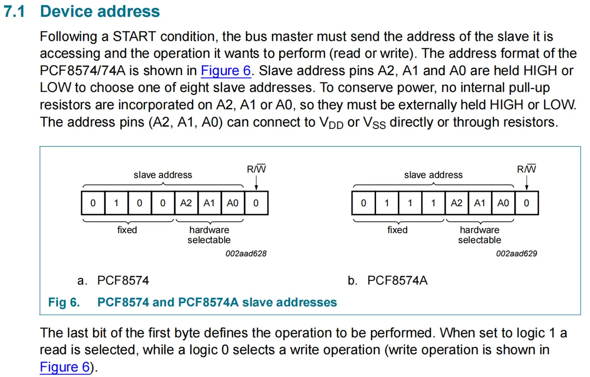
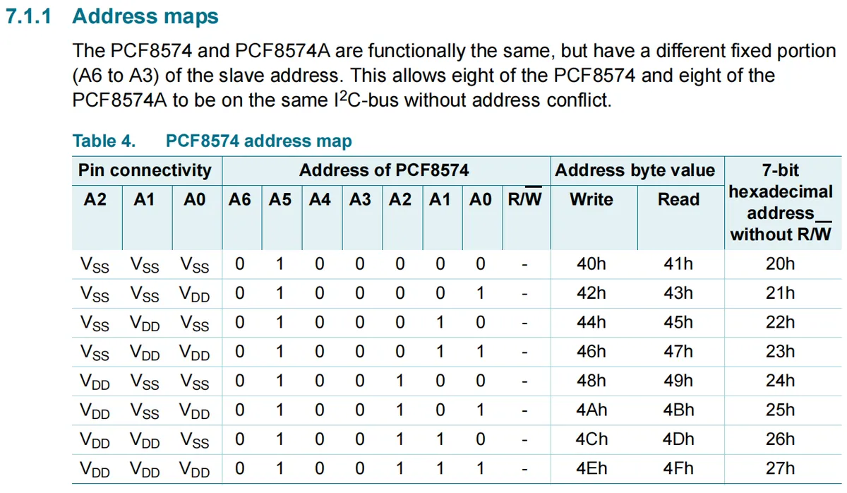
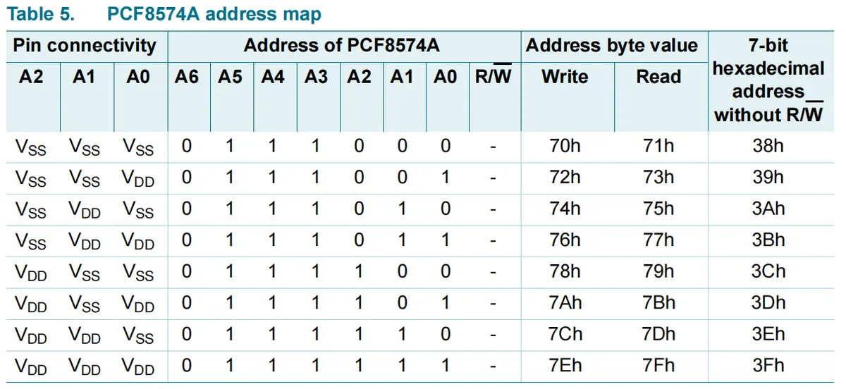
We can configure the high and low levels of A2 A0 to set the chip address, and the specific addresses are as follows:
2.7 Communication Interfaces and Related Protocols
This chip adopts I2C communication interface.
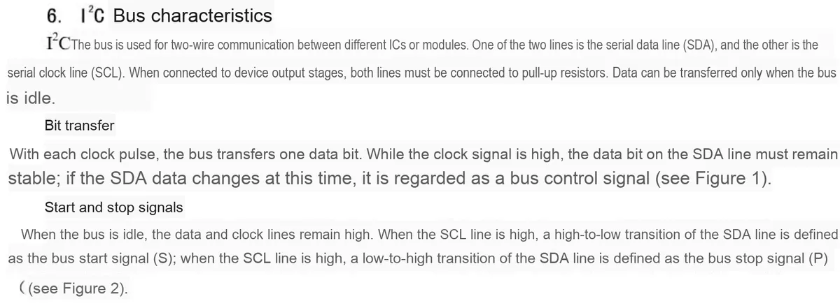
2.7.1 I2C Communication Related
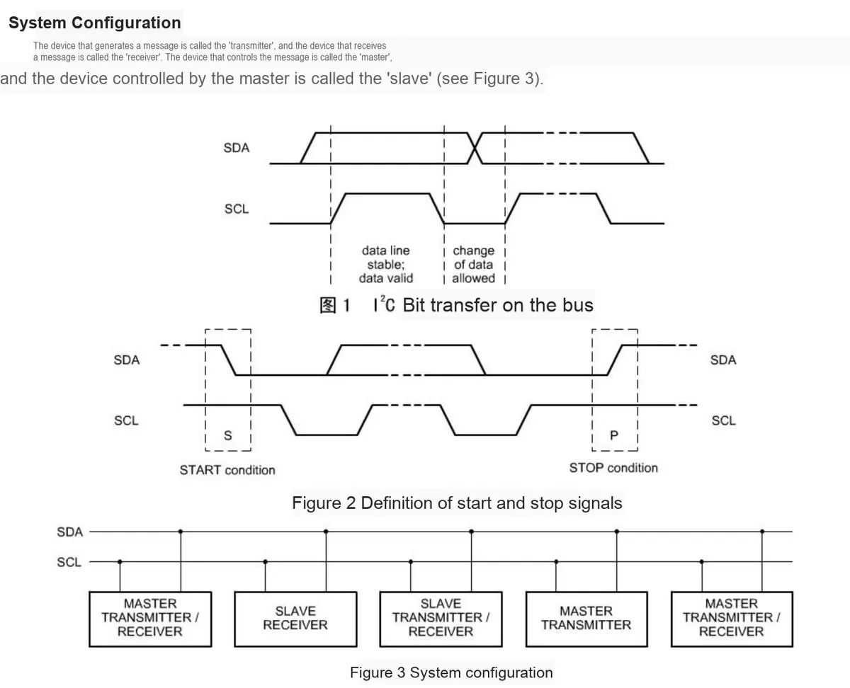
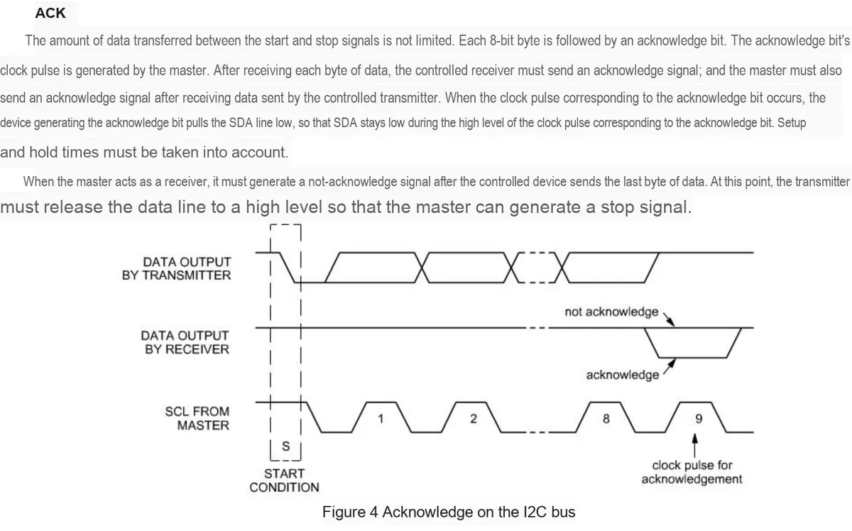
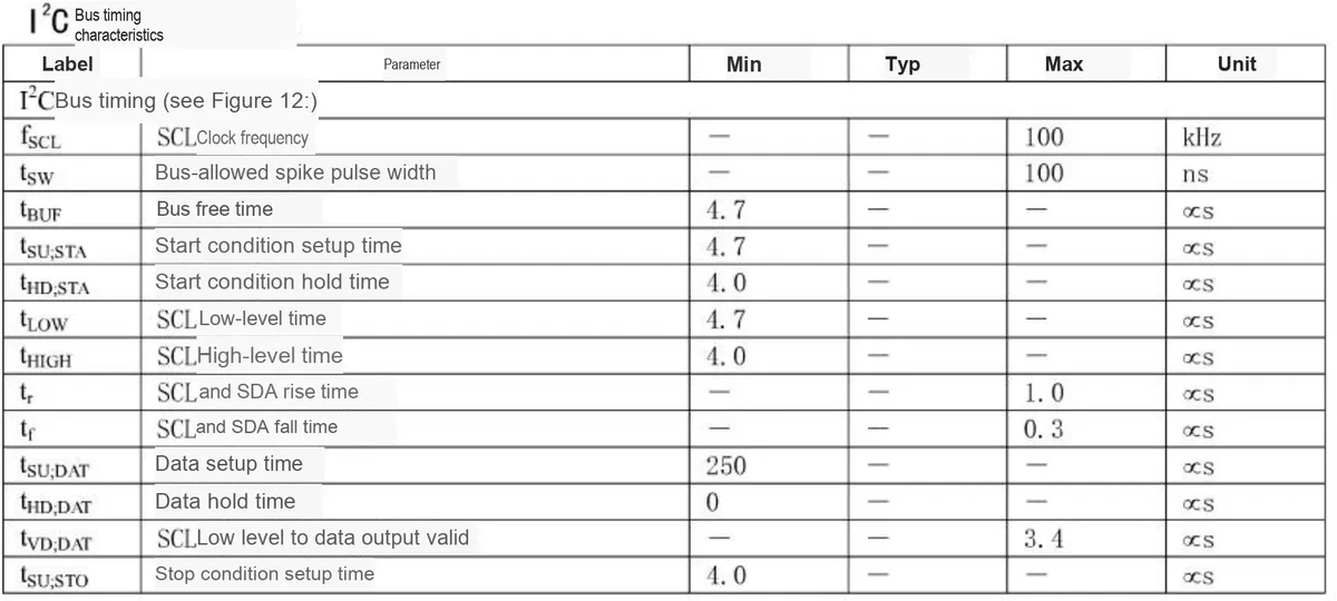
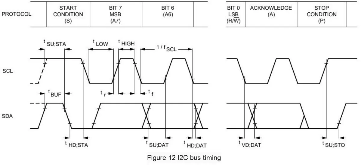
2.7.2 Quasi-bidirectional IO
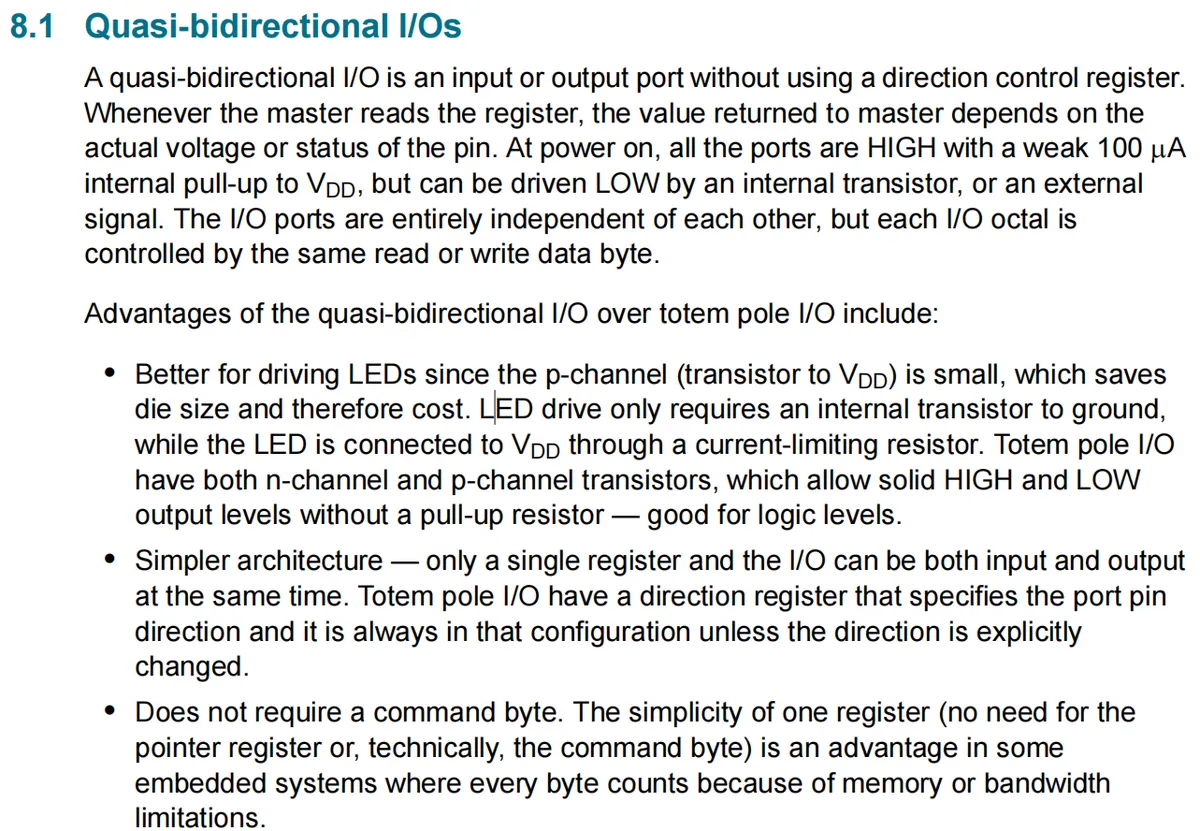
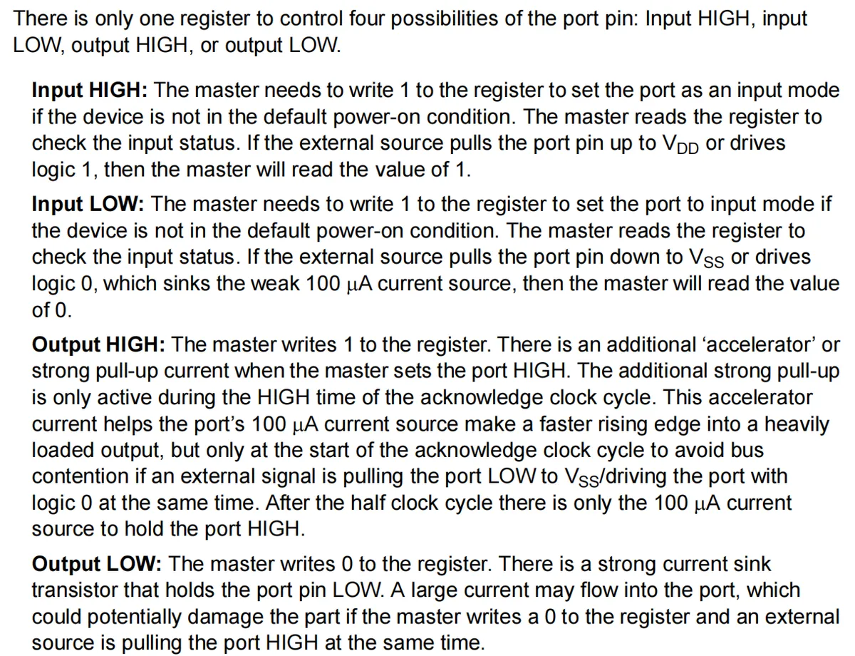
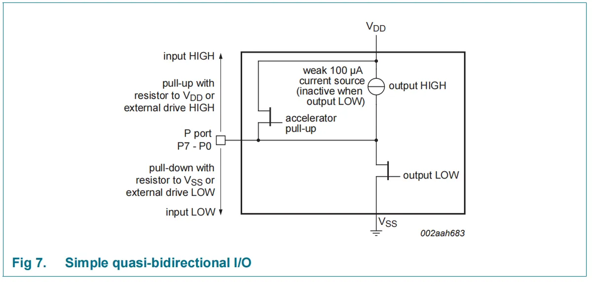
The PCF8574 adopts a quasi-bidirectional IO design, eliminating the need for a separate direction register, and can control four states of IO — input high, input low, output high, and output low — through a single register:
- By default upon power-up, all
IOpins are at high level (with a 100μA weak pull-up); to configure a pin as input, write 1 to the corresponding register, and the host can read the external level by reading the register (reads 1 if the external pin is pulled high, reads 0 if pulled low); - Outputting a high level involves writing a 1 to the register; during the acknowledge clock cycle, an "accelerated pull-up" is triggered to make the auxiliary voltage rise rapidly, after which it is maintained solely by a weak pull-up.
- When outputting a low level, 0 is written to the register, and the level is pulled low by the strong current-sinking transistor; however, it is necessary to avoid external forced pulling-up of the IO which may cause device damage.
Compared with the totem-pole IO, this design has the advantages of being adaptable to LED driving, simple architecture, and no need for command bytes (saving memory/bandwidth), and its functions are implemented in the circuit by the cooperation of a weak pull-up current source, an accelerated pull-up transistor, and an output low-sink current transistor.
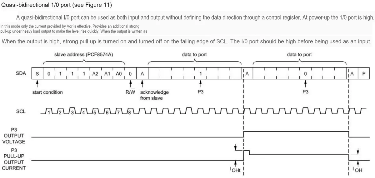
2.7.3 Writing to and Reading from Ports
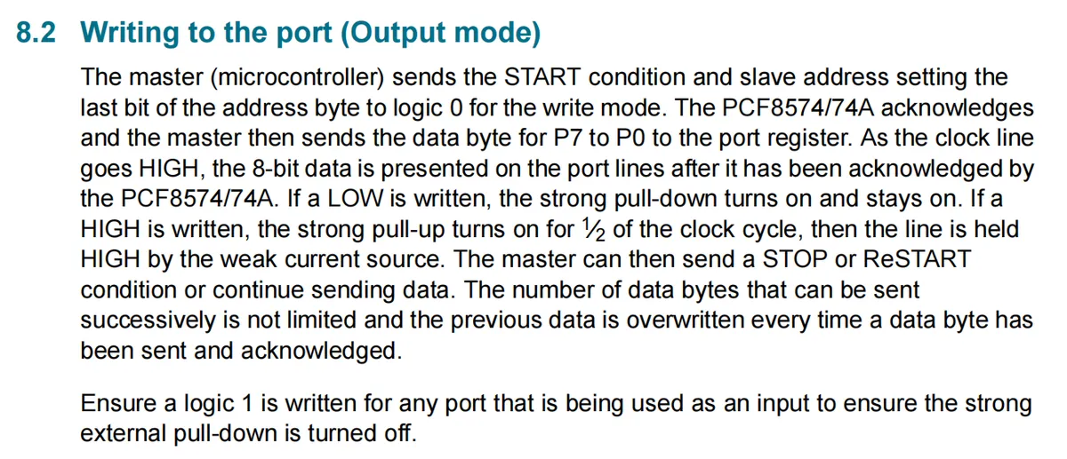
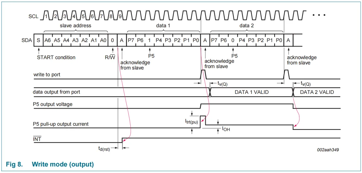

PCF8574 write port (output mode) follows the I²C communication process: the master first sends a START condition, then transmits the slave address (with the last bit set to 0 to indicate write mode); after the device acknowledges, the master sends 8-bit data from P7 to P0; once the clock line is pulled high and the device acknowledges, the data takes effect — when writing 0, the strong pull-down transistor remains continuously on; when writing 1, the strong pull-up only assists the voltage rise for half a clock cycle, and the high level is subsequently maintained by a 100μA weak pull-up.The master can continuously send multi-byte data (new data will overwrite old data), and finally send STOP / ReSTART to terminate;meanwhile, note that if the port is configured as an input, you must write 1 to it to turn off the strong pull-down transistor.
Combined with the Sequence Diagram and code examples, this process can be simplified as " START → Slave Address + Write → ACK → Data → ACK (repeatable) → STOP ", and the timing also reflects details such as the valid delay of data output and the dynamic change of pull-up current.
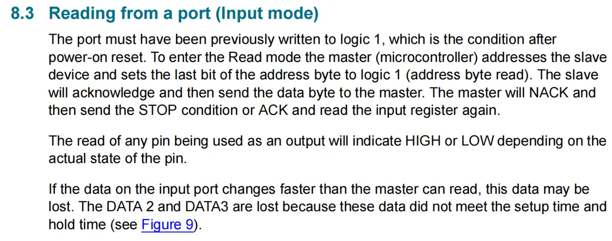
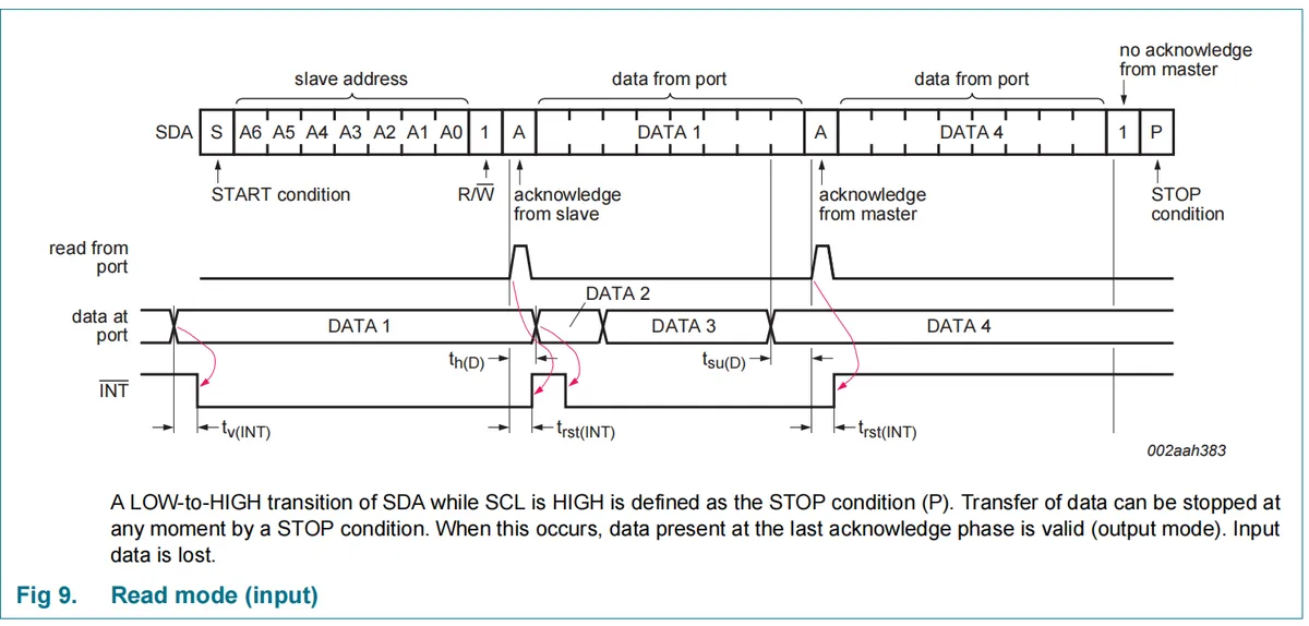

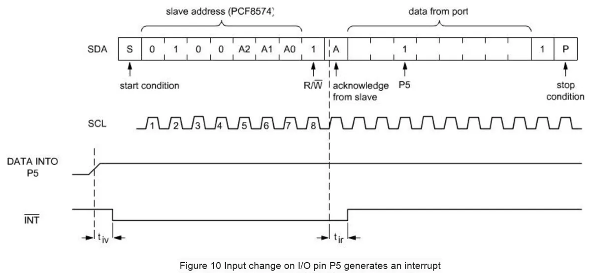
PCF8574 ’s port reading (input mode) is subject to a prerequisite: the port must be pre-written with 1 (this is the default state after power-on reset); its operation follows the I²C protocol: the master first sends a START condition, then transmits the slave address (with the last bit set to 1 to indicate read mode), and after the device acknowledges, it sends the port data byte to the master; the master can either send a NACK followed by a STOP to terminate the read, or send an ACK to continue reading the next byte.Note: Reading an output pin returns its actual logic level. If the input data changes faster than the host's reading pace, data will be lost due to failure to meet setup/hold time requirements. Combined with the Sequence Diagram and code examples, the process can be simplified as " START → Slave Address + Read → ACK → Data → ACK (repeatable) → Data → NACK → STOP ", and the timing also reflects the delay relationship between interrupts and data changes.
2.7.5 Power-on Reset
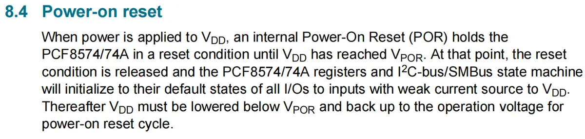
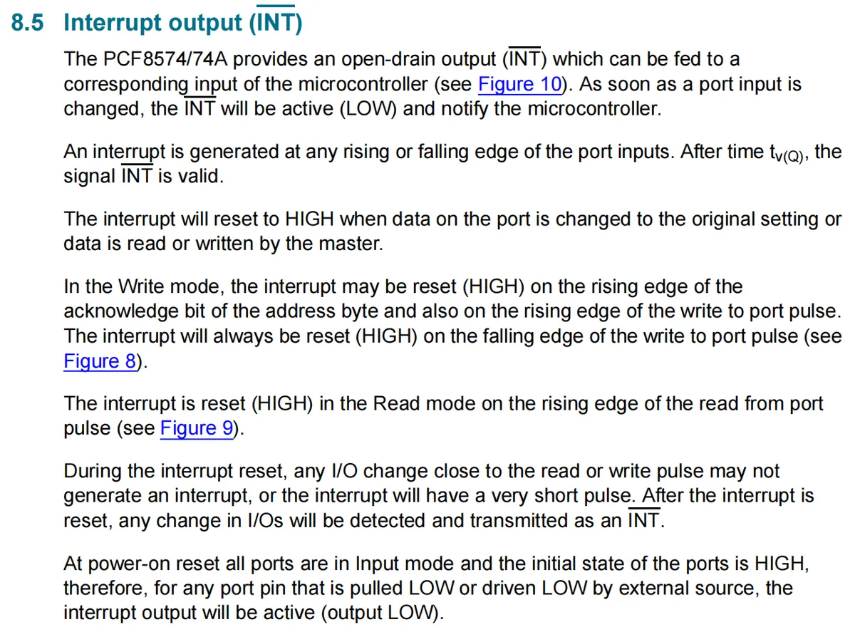
PCF8574 has the following power-on reset (POR) function logic: when VDD starts supplying power, the internal power-on reset circuit keeps the chip in a reset state until the VDD voltage reaches the power-on reset threshold VPOR; at this point the reset is released, and the chip's registers, I²C / SMBus finite-state machine will be initialized to the default state — all IO ports are configured as input mode with a weak current source pulled up to VDD. If you need to re-trigger the power-on reset subsequently, you must lower VDD below VPOR and then raise it back to the operating voltage to complete the reset cycle.
2.7.6 Interrupt Function
2.8 PCB Routing Precautions
None.
III. Instructions for Circuit Engineering and Module Usage
3.1 Circuit Source Engineering
To obtain the source code of the circuit, please follow the official account [Freak Embedded]
3.2 Module Usage Instructions
The schematic diagram of this module is shown below:
SCH_8-bit IO Port Expansion Module Based on PCF8574_v1.2_2025-12-10.pdf 2.2 MB
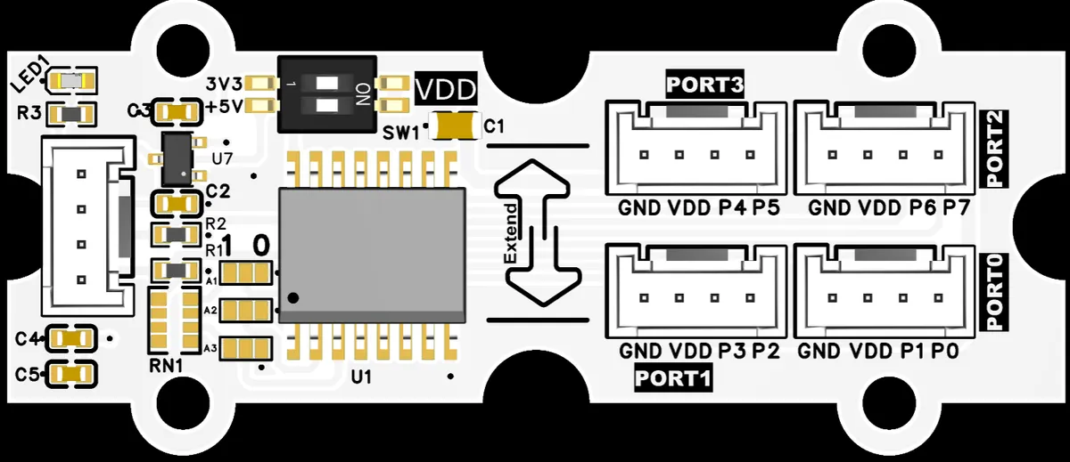
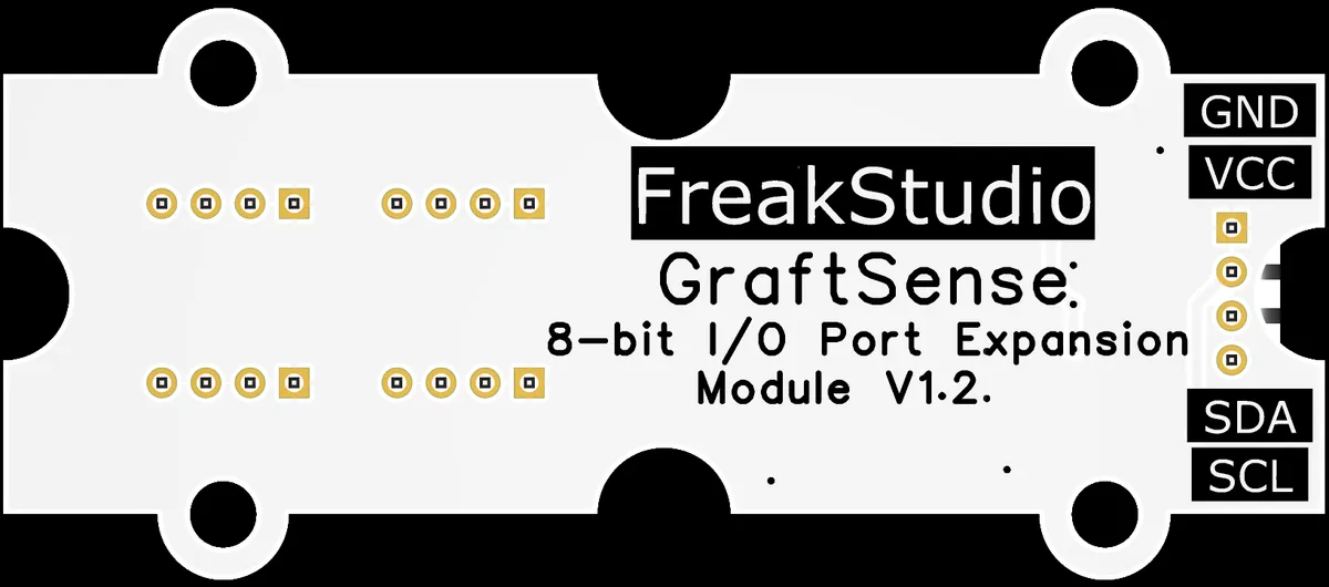
This module provides an I2C communication interface: it communicates with the host, and the PORT0 to PORT3 interfaces correspond to the P0 to P7 IO ports. Note that their driving capability is weak: the module's IO ports adopt the quasi-bidirectional structure of PCF8574, with a high-level output current of only approximately 100μA, which can only directly drive extremely small loads such as LEDs; if you need to drive high-current devices such as relays and motors, you must connect an external triode or MOSFET to enhance the driving capability, and it is more stable to prefer the current sinking mode (IO pulls down to carry load).In addition, before use, the I2C address shall be determined via short-circuit point configuration A0 / A1 / A2, and the power supply can be selected via SW1.
3.3 Application Experiment
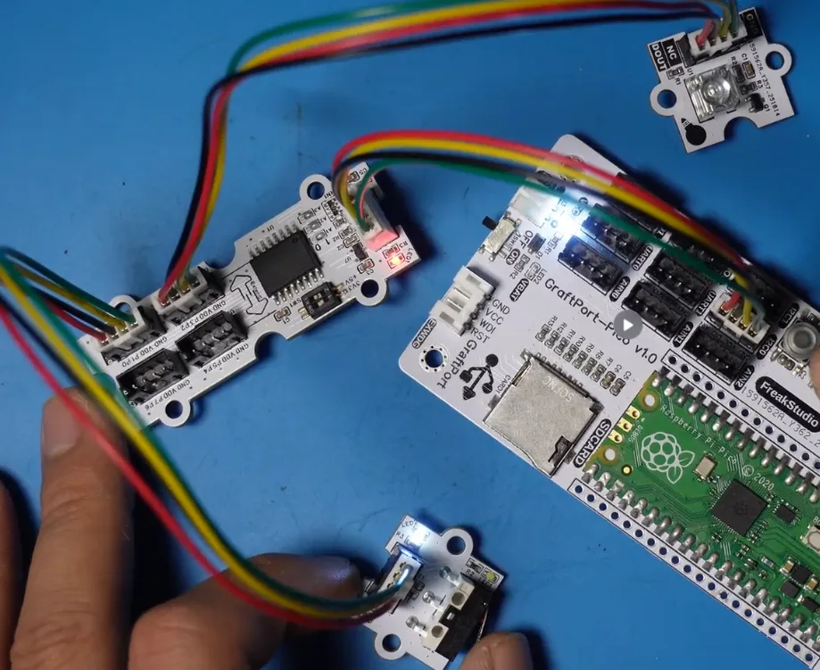
Here, we use the GraftPort-RP2040 development board for testing, and connect the 8-bit IO port expansion module based on PCF8574 to communicate with the main controller via the I2C interface; meanwhile, two types of functional modules are additionally connected to this expansion module:
- Piranha LED light module is connected to the 8-bit I/O port expansion module based on PCF8574 via
port0; - Limit switch sensor module is connected to the 8-bit IO port expansion module based on PCF8574 ’s
prot1.
Here, we first use the HY2.0-4P cable to connect the module to the GraftPort-RP2040 development board's I2C0 interface:
The module connections are shown in the following table:
Development Board Pins | Module Pins | Description |
Pin 4 |
| I2C data transmission line, corresponding to |
Pin 5 |
| I2C clock signal line, corresponding to |
- |
| Connect the Piranha LED light module |
- |
| Connect the limit switch module |
Here, we need to search for relevant driver packages on uPyPI: https://upypi.net/zh/
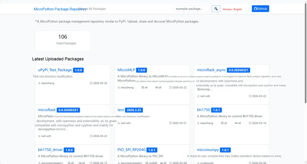
Enter pcf8574_io8_driver to search, and the following will be displayed:

Click to copy the local installation command:
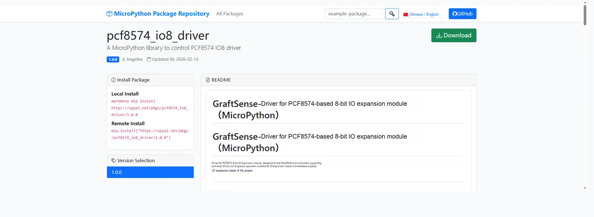
Here, we can use the mip tool to import module driver library code. Below are the usage commands for the mpremote tool:
mpremote mip install github:FreakStudioCN/GraftSense-Drivers-MicroPython/input/pcf8574_io8_driverAfter importing the 8-bit IO port expansion module based on PCF8574 - MicroPython driver code, copy the following main.py code into our project:
# Python env   : MicroPython v1.23.0
# -*- coding: utf-8 -*-
# @Time    : 2025/9/23 PM 5:44
# @Author  : 缪贵成
# @File    : main.py
# @Description : 8-bit IO expander driver test file

# ======================================== Import Modules =========================================
# Import the I2C and Pin modules
from machine import I2C, Pin
# Import the time module
import time
# Import the PCF8574 and PCF8574IO8 modules
from pcf8574 import PCF8574
# Import the PCF8574IO8 module
from pcf8574_io8 import PCF8574IO8

# ======================================== Global Variables ============================================

PCF8574_ADDR = None

# ======================================== Functions ============================================

# ======================================== Custom Classes ============================================

# ======================================== Initialization configuration ===========================================

time.sleep(3)
print("FreakStudio:PCF8574 Five-way Button Test Program")
# Initialize I2C
i2c = I2C(0, scl=Pin(5), sda=Pin(4), freq=100000)
# Start scanning for devices on the I2C bus and return a list of slave addresses
devices_list: list[int] = i2c.scan()
print('START I2C SCANNER')
# If the devices list is empty, no device is connected to the I2C bus
if len(devices_list) == 0:
    # If not empty, print the slave device addresses
    print("No i2c device !")
else:
    # Iterate over the slave device address list
    print('i2c devices found:', len(devices_list))
for device in devices_list:
    # Check whether the device address is the PCF8574 address
    if 0x20 <= device <= 0x28:
        # The device found is the PCF_8574 address
        print("I2c hexadecimal address:", hex(device))
        PCF8574_ADDR = device
# Initialize PCF8574
pcf = PCF8574(i2c, PCF8574_ADDR)
# check if device is present
try:
    if pcf.check():
        print("PCF8574 detected successfully.")
except OSError as e:
    print("Error: PCF8574 not found!", e)
# PCF8574IO8 init
# Initialize module pin states: PORT0=(0,1), PORT1=(1,0), PORT2=(1,1), PORT3=(0,0)
ports_init = {0: (1, 1), 1: (1, 1), 2: (1, 1), 3: (1, 1)}
io8 = PCF8574IO8(pcf, ports_init=ports_init)
print("PCF8574IO8 initialized with default port states:", io8.ports_state())
time.sleep(3)

# ========================================  Main Program  ============================================
# Blink pin 2 of port 2
io8.set_port(1,0)
time.sleep(1)
io8.set_port(1,2)
time.sleep(1)
io8.set_port(1,0)
time.sleep(1)
io8.set_port(1,2)

while True:
    if not io8.get_pin(0):  # When pin 0 is low (not 1 → False, not 0 → True)
        io8.set_port(1, 2)  # Set port 2 to value 2
        print("Button triggered, set port2 to 1")  # Corrected print
    else:  # When pin 0 is high
        io8.set_port(1, 0)  # Set port 2 to value 0
Here, we first find the device address of I2C through scanning and complete the initialization, then configure the initial port state of PCF8574, and then configure the initial port state of PCF8574-IO8. After that, we cyclically detect the level change of pin 0. When pin 0 is triggered to a low level, we control the state of port 2 and print the trigger information, so as to implement the interaction logic between the button and the extended IO.
To flash the code, open a terminal and use the mpremote tool to connect to the main controller; the output is as follows:
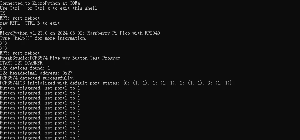
It can be seen that after the programmed regular flashing of the lamp ends, the lamp bead will light up when the button is pressed.
Combined with the physical diagram and terminal output, it can be seen that the program has successfully scanned I2C on the bus PCF8574 device and completed initialization. The PCF8574 module connected to the Raspberry Pi Pico in the figure and the LED hardware correspond to the operation of Button triggered in the log, and also match the lighting state of the LED in the figure, indicating that the program has implemented the detection and control functions of the PCF8574 extended IO, and both the hardware connection and program logic are working properly.
IV. Drivers
pcf8574_io8_driver.zip 15 KB
5. BOM & Recommended Alternative Parts
None.
VI. Revision History
Document Version | Date of Revision | Modifier | Revised Content |
v1.0 | 2025-11-22 | Li Zisheng | Initialize the document |
v1.1 | 2025-12-29 | Li Zisheng | Added application experiments and production files |
v1.2 | 2025-12-31 | Xin Ruili | Create an open version of the document based on the internal document version v1.1. |
v1.3 | 2026-03-29 | Xin Ruili | Modified the application experiment section. |
VII. Relevant Materials
7.1 Chip Datasheet
PCF8574_PCF8574A.pdf 892 KB
7.2 Unique Icons for PCB Silk Screen