Contents
- I. Module Introduction
- II. Introduction to Major Chips
- 2.1 Chip Overview
- 2.2 Pin Definition
- 2.3 Functional Block Diagram
- 2.4 Performance Parameters
- 2.5 Reference Circuit
- 2.6 Chip Configuration
- 2.7 Communication Interfaces and Related Protocols
- 2.8 PCB Routing Precautions
- III. Circuit Engineering
- 3.1 Circuit Source Engineering
- 3.2 Module Usage Instructions
- 3.3 Application Experiment
- IV. Drivers
- 5. BOM & Recommended Alternative Parts
- VI. Revision History
- VII. Relevant Materials
- 7.1 Chip Datasheet
- 7.2 Unique Icons for PCB Silkscreen
I. Module Introduction
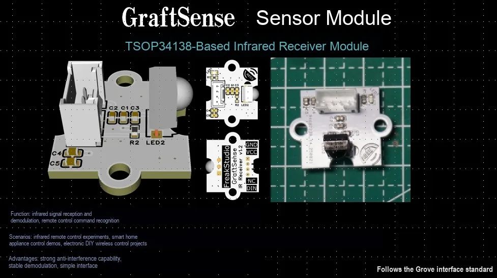
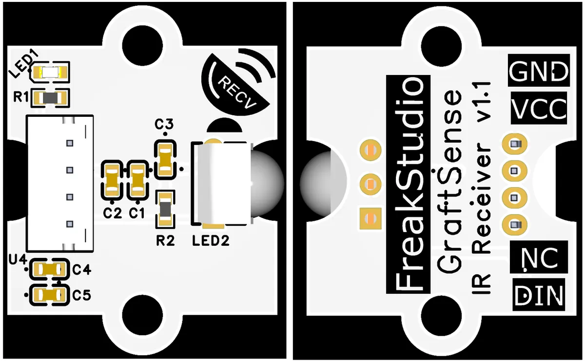
The infrared receiving module based on TSOP34138 takes the TSOP34138 infrared receiver as the core, integrates circuits such as power filtering and status indication, can demodulate 38kHz carrier infrared signals and output digital level (DIN pin); it has an operating voltage range of 2.5–5.5V, a typical receiving distance of up to 45 meters, and supports wide-temperature operation from -25 to 85°C;The module connects to the main control device (such as a microcontroller) through pins including GND, VCC, and DIN. It is suitable for scenarios such as infrared remote control signal reception and short-range infrared data communication, featuring strong anti-interference capability, high sensitivity, and Plug and Play.
II. Introduction to Major Chips
2.1 Chip Overview
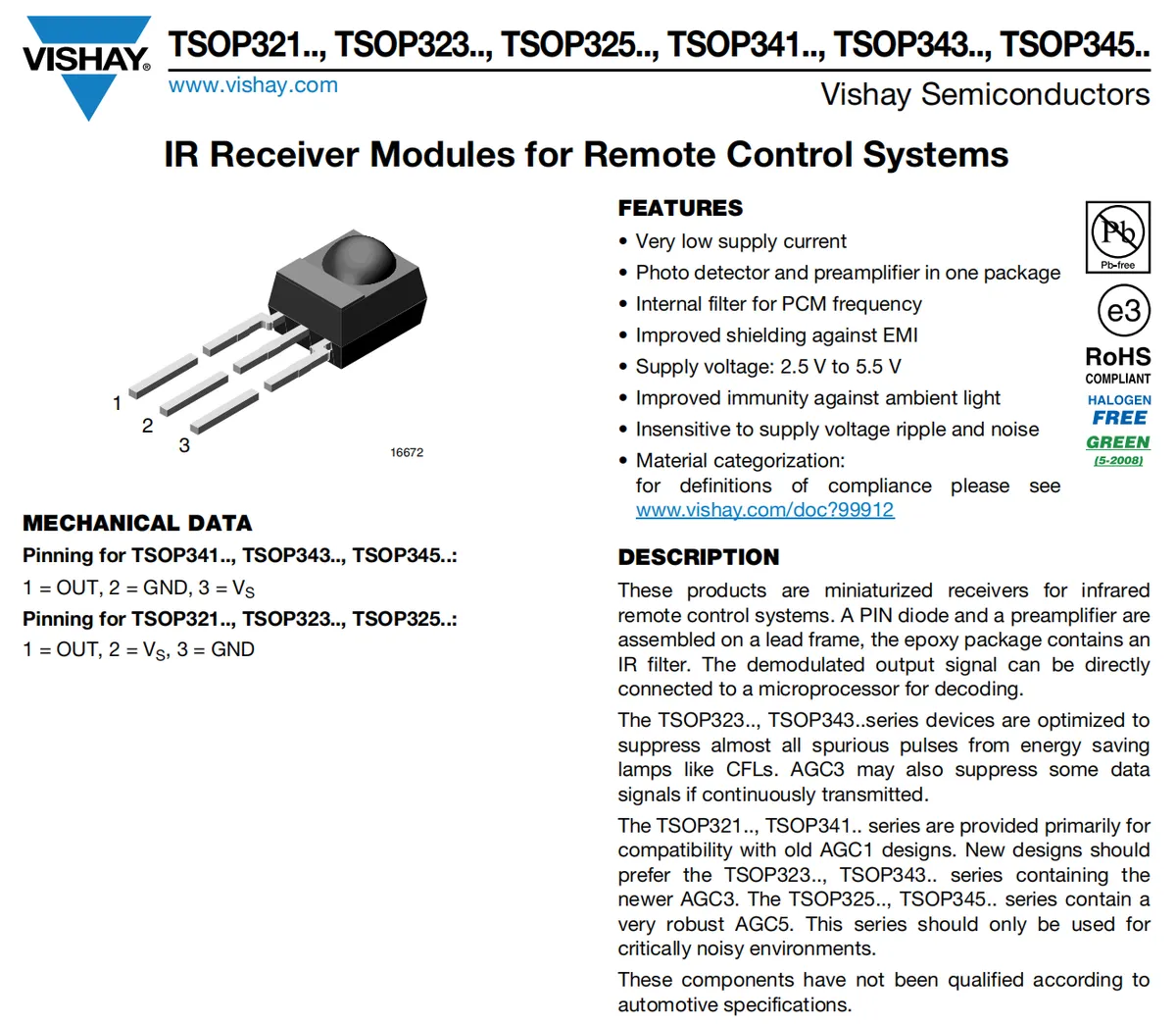
TSOP34138 is Vishay 's integrated infrared receiver, which incorporates a photodetector and a preamplifier, integrates a 38kHz bandpass filter and anti-EMI design, and can directly demodulate infrared remote control signals and output digital levels via the OUT pin; it operates over a voltage range of 2.5–5.5V with ultra-low power consumption, features strong resistance to ambient light interference, and is suitable for noisy electromagnetic environments; its pin configuration is defined as 1= OUT (signal output), 2= GND (ground), 3= Vs (power supply), and can be directly interfaced with main control devices such as microcontrollers;Widely used in infrared remote control systems such as those for televisions and air conditioners, it can stably receive infrared signals within a maximum distance of 45 meters, serving as a core component for infrared data reception and decoding.
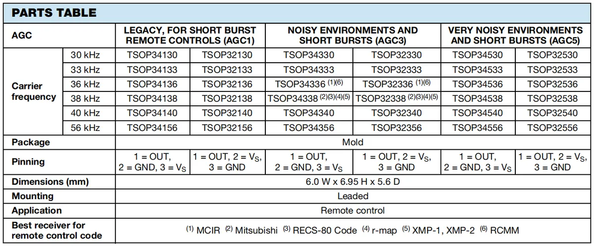
Different models of integrated TSOP3x infrared receivers have different demodulatable signal frequencies and pin definitions.
2.2 Pin Definition
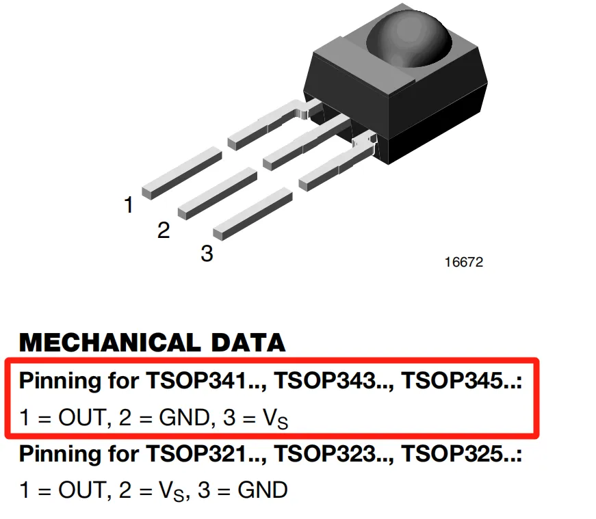
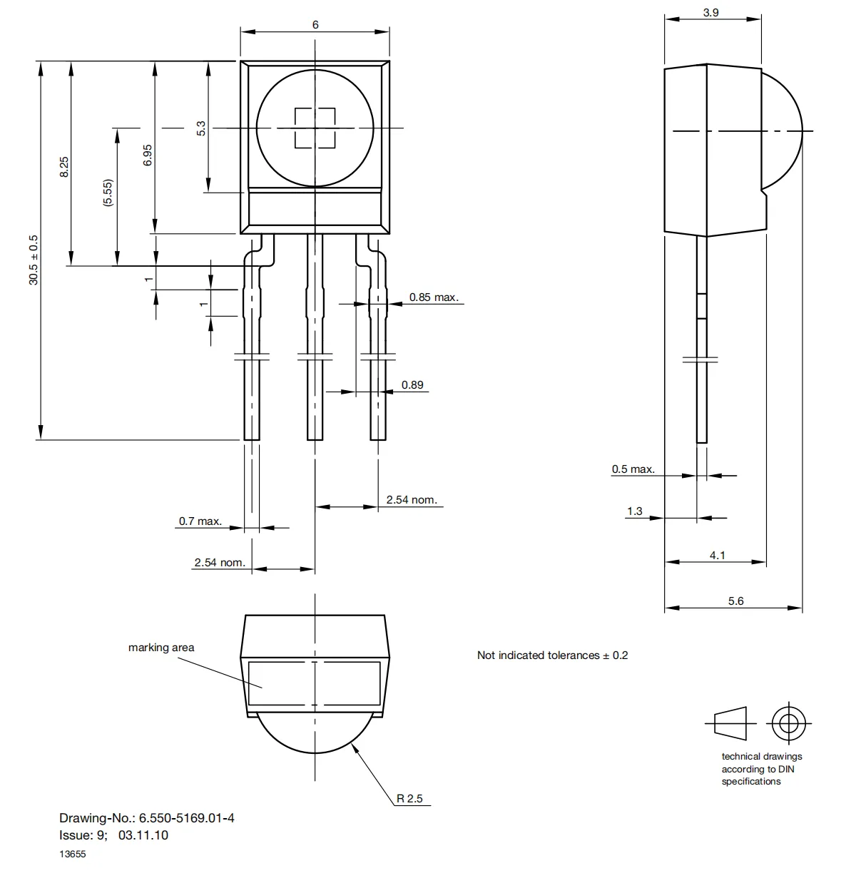
2.3 Functional Block Diagram
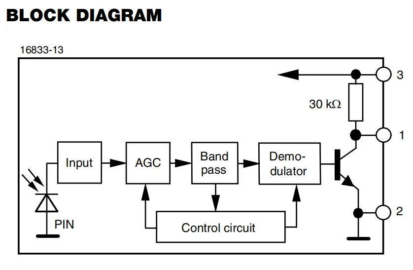
This functional block diagram illustrates TSOP34138 the internal signal processing flow of the infrared receiver:
- First,
PINdiode receives the infrared optical signal and converts it into an electrical signal; - After being initially processed by the input stage (
Input), the electrical signal is sent to the Automatic Gain Control (AGC) module.AGC, coordinated by the control circuit (Control circuit), automatically adjusts the gain according to the signal strength to adapt to infrared signals from different distances; - The signal then enters a band-pass filter (
Band pass), whose filtering frequency (e. g., the 38kHz carrier commonly used in infrared remote controls) is set by the control circuit to filter out irrelevant frequency interference; - The amplitude-modulated signal after band-pass filtering is sent to the demodulator (
Demo - dulator) to demodulate the original digital signal; - Finally, the demodulated signal is output from pin 1 (
OUT) via the output stage (including transistors, etc.), completing the conversion from "infrared light to digital electrical signal".
2.4 Performance Parameters
2.4.1 Electrical Parameters
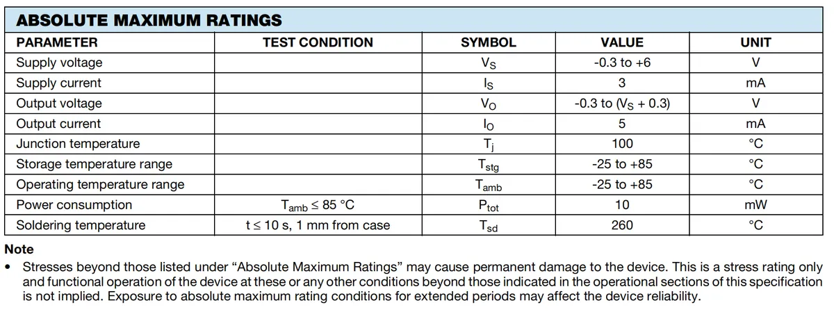
- Power Supply Parameters
- Supply Voltage (
VS): ranges from −0.3 V to + 6 V. This specification not only limits the reverse withstand voltage (to prevent breakdown caused by negative voltage) but also defines the upper limit of forward power supply (≤6 V) to avoid device damage due to overvoltage. - Supply Current (
IS): The maximum value is 3 mA, which reflects the "low power consumption" characteristic of the device; the power supply in the design shall be capable of stably providing a current not exceeding 3 mA.
- Supply Voltage (
- Output Parameters
- Output Voltage (
VO): ranging from −0.3 V to (VS+ 0.3) V. The voltage swing of the output pin is constrained by the supply voltage, and its reverse voltage shall not be lower than -0.3 V to ensure the electrical safety of the output stage (it needs to match the subsequent circuit, such as the voltage range of the microcontroller IO port). - Output Current (
IO): The maximum value is 5 mA, which specifies the upper limit for the "sourcing/sinking current" of the output pin. The current of the subsequent stage load must not exceed this value to avoid overload damage to the output stage.
- Output Voltage (
- Temperature-related parameters
- Junction temperature (
Tj): with a maximum rating of 100 ∘C, which is the temperature limit of the internal PN junction of the device; exceeding this value will cause permanent device failure, so it is necessary to avoid junction temperature overrun through thermal design (such as controlling ambient temperature and reducing power consumption). - Storage temperature range (
Tstg):−25 to + 85 °C, which refers to the storage temperature range for the device in a non-operating state; exceeding this range may lead to material or performance degradation due to temperature variations. - Operating temperature range (
Tamb):−25 to + 85 ∘C, which refers to the ambient temperature range where the device operates normally; beyond this range, the infrared receiving sensitivity, output signal stability and other performance cannot be guaranteed.
- Junction temperature (
- Power Consumption and Welding Parameters
- Total power consumption (
Ptot, test condition:Tamb≤ 85 ∘C): the maximum value is 10 mW, and the total power consumption is calculated byP=VS×IS; during design, ensure that this product does not exceed the limit to prevent the device from overheating. - Soldering temperature (
Tsd, test conditions: t ≤10 s, at a distance of 1 mm from the housing): The maximum value is 260 ∘C. During soldering, the temperature and time must be strictly controlled to avoid damage to the device caused by high temperature (such as failure of pins or internal circuits due to thermal stress).
- Total power consumption (
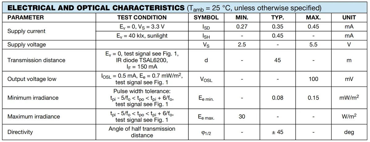
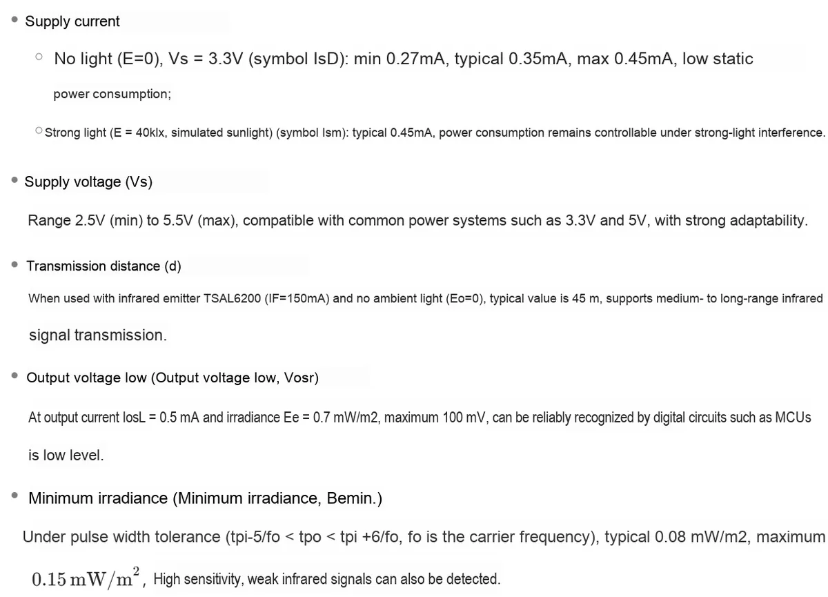
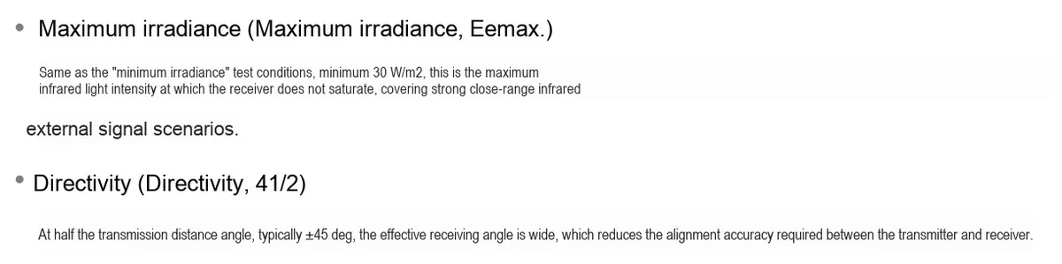
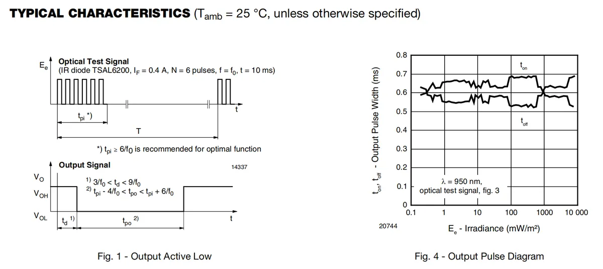
2.4.2 Photoelectric Characteristics
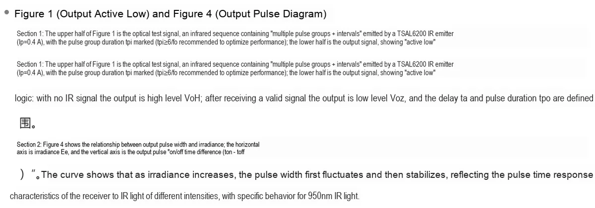
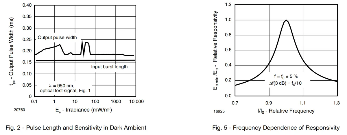
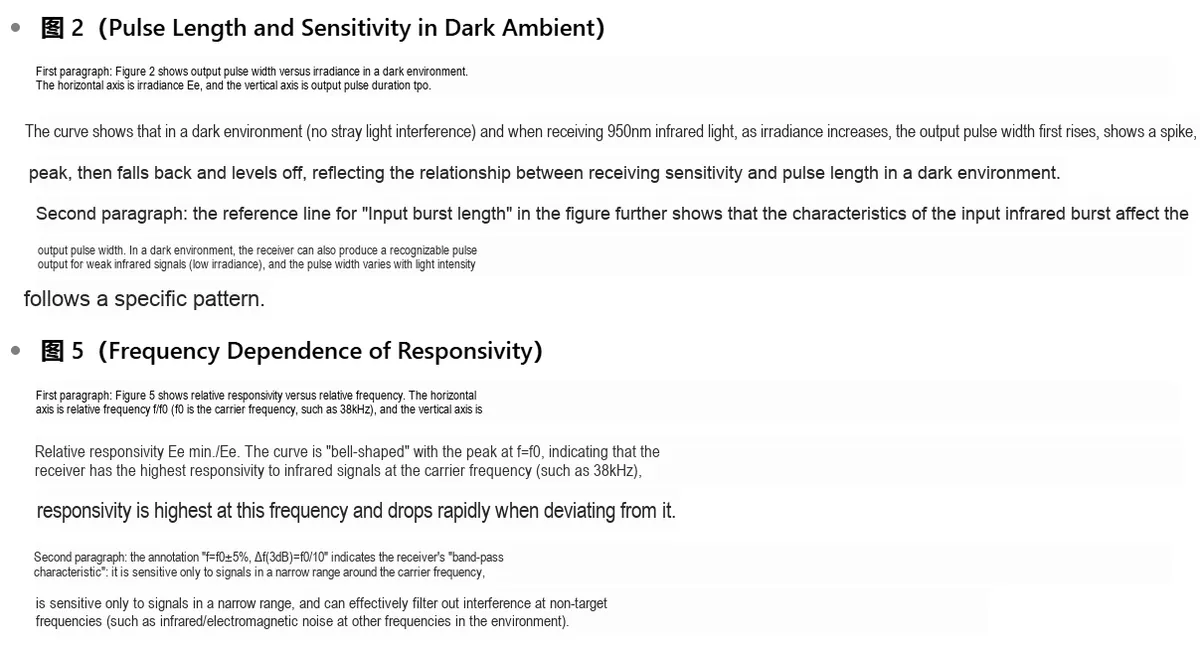
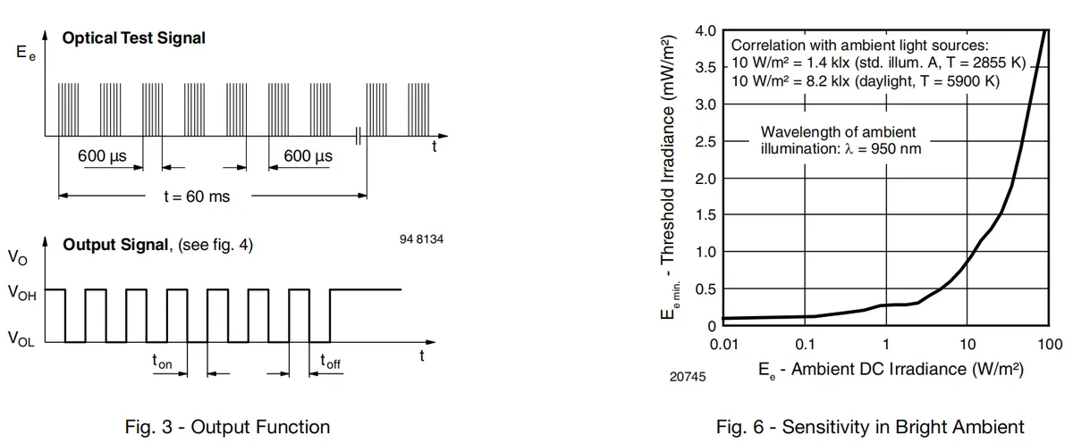
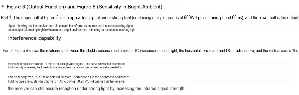
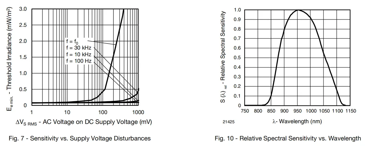
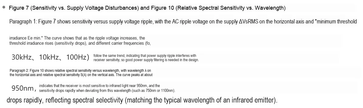
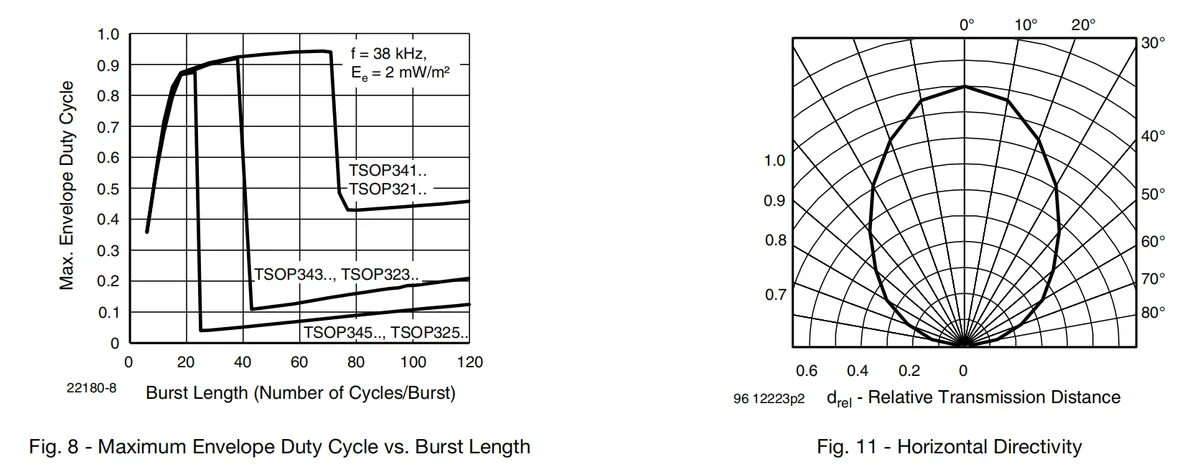
2.5 Reference Circuit
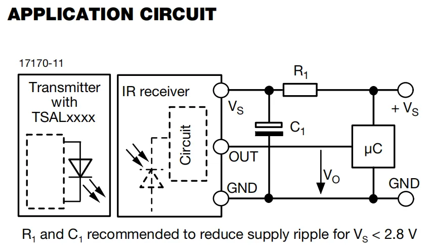
This reference circuit is a typical application of the interaction between infrared transceiver and microcontroller: the left part consists of TSAL series transmitting tubes to form an infrared transmitting end, which transmits modulated infrared signals; the intermediate infrared receiving module operates via three pins: VS (power supply), OUT (signal output), and GND (ground), which receives the infrared signal and demodulates it into a digital level;The right side passes through R1 and C1 to form an RC filter network (recommended for use when VS < 2.8 V, which is used to reduce power supply ripple) to stably supply power to the receiving head. Besides, the OUT pin of the receiving head is directly connected to the IO port of the microcontroller(μC), and GND shares a common ground with the microcontroller, so that the microcontroller can collect and process infrared signals, realizing a complete link of "transmission → reception → digital processing".
2.6 Chip Configuration
None.
2.7 Communication Interfaces and Related Protocols
None.
2.8 PCB Routing Precautions
None.
III. Circuit Engineering
3.1 Circuit Source Engineering
To obtain the source project of the circuit, please follow the official account [Freak Embedded]
3.2 Module Usage Instructions
The schematic diagram of this module is shown below:
SCH_TSOP34138-Based Infrared Receiver Module_v1.1_2025-09-18.pdf 1.3 MB
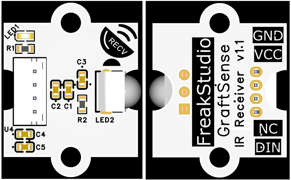
This module provides a digital output interface:
- Digital Output (
DIN): This is the digital signal output terminal of the module, used to output the demodulated infrared signal. When the module receives valid infrared light (such as an infrared remote control signal that meets the carrier frequency and coding rules),DINwill output the corresponding digital level (usually active low, and high level when there is no valid signal); an external main control device (such as a single-chip microcomputer or microcontroller) can read the level changes of theDINpin to parse infrared commands or data, so as to realize the reception and digital processing of infrared signals.
3.3 Application Experiment
Here, we use the GraftPort-RP2040 development board for testing, and connect the IR333C-based infrared transmitting module and the TSOP34138-based infrared receiving module to the main controller via the DIO interface for communication.
Here, we first use the HY2.0-4P cable to connect the module to the GraftPort-RP2040 development board's DIO0 and DIO1 interfaces:
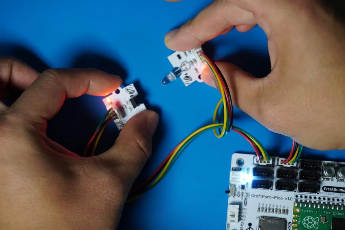
The module connections are shown in the following table:
Infrared Transmit Module Based on IR333C:
Development Board Pins | Module Pins | Description |
Pin 6 |
| Infrared signal transmission output pin |
Pin 7 |
| - |
Infrared receiving module based on TSOP34138:
Development Board Pins | Module Pins | Description |
Pin 14 |
| - Infrared signal receiving input pin |
Pin 15 |
| - |
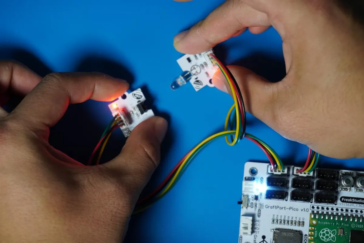
Here, before conducting communication, we need to align the infrared transceiving units between the modules as much as possible:
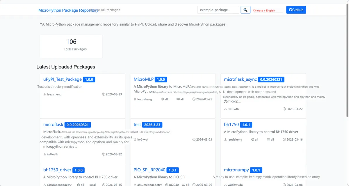
Here, we need to search for the relevant driver packages on uPyPI: https://upypi.net/zh/
Enter irtranslation_driver to search, and the following will be displayed:
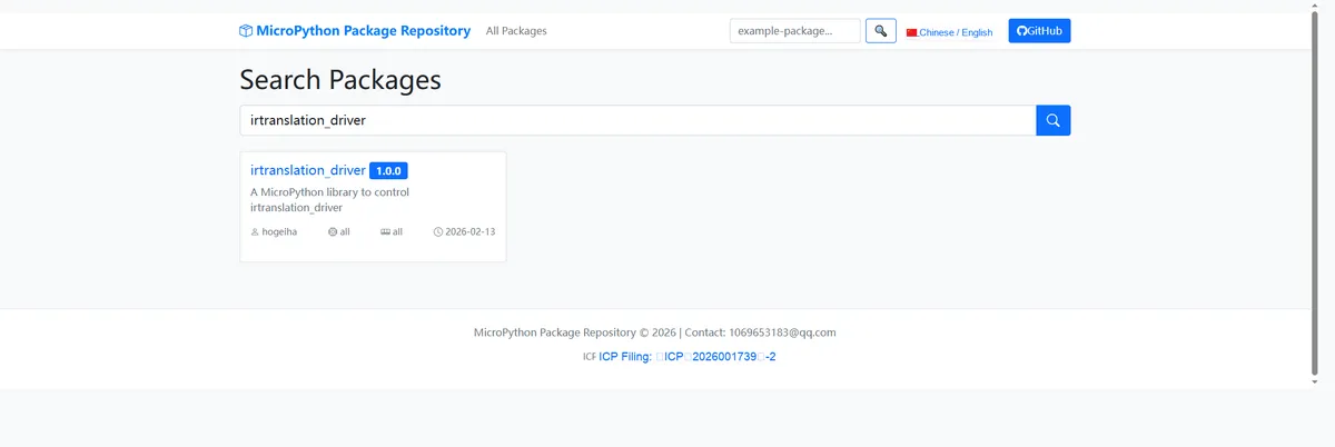
Click to copy the local installation command:
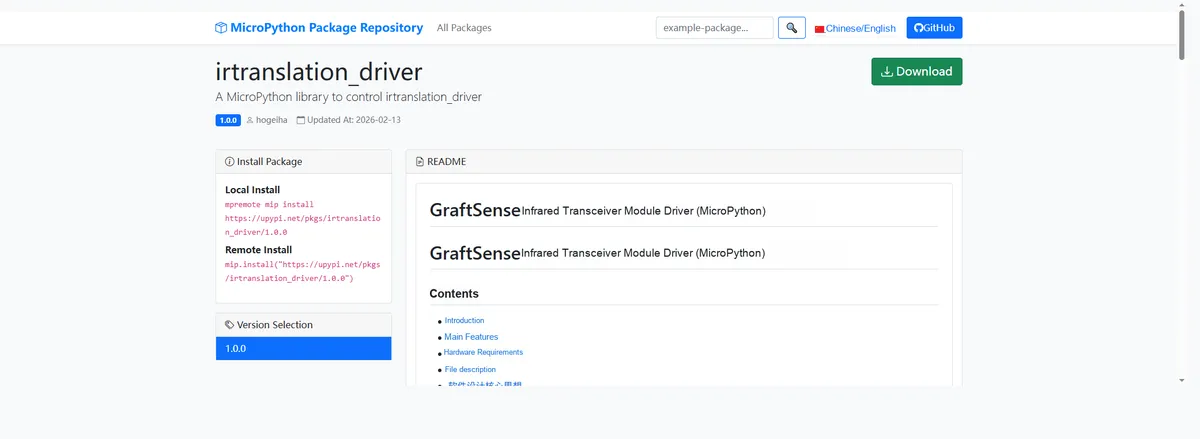
Here, we can use the mip tool to import module driver library code. The following are the usage commands for the mpremote tool:
mpremote mip install github:FreakStudioCN/GraftSense-Drivers-MicroPython/communication/irtranslation_driverAfter importing the IR infrared transceiver driver - MicroPython driver code, copy the following main.py code into our project:
# Python env   : MicroPython v1.23.0
# -*- coding: utf-8 -*-
# @Time    : 2025/8/26 10:11 PM
# @Author  : 缪贵成
# @File    : main.py
# @Description : Test file for the nec_16 protocol on the Raspberry Pi Pico

# ======================================== Import Modules =========================================

import time
from machine import Pin
from ir_tx.nec import NEC
# nec_16 has three parameters in the callback function
from ir_rx.nec import NEC_16

# ======================================== Global Variables ============================================

# ======================================== Functions ============================================

# If using nec_8, pass variable-length arguments; this is nec_16

def ir_callback(addr: int, cmd: int, repeat: bool) -> None:
    """
    NEC protocol receive callback function (3-parameter version).

    Args:
        addr (int): Received address
        cmd (int): Received command code
        repeat (bool): Whether this is a repeat code (True = yes, False = no)

    Notes:
        The callback is called by the NEC receive module and is not ISR-safe.
        Output the received data to the serial port.

    ==========================================

    NEC IR signal receive callback (3-parameter version).

    Args:
        addr (int): Received address
        cmd (int): Received command
        repeat (bool): Repeat flag (True = yes, False = no)
    Notes:
        Called by NEC IR receiver. Not ISR-safe.
        Prints received data to REPL.
    """
    print(f"[RX] Address=0x{addr:04X}, Cmd=0x{cmd:02X}, Repeat={repeat}")

# ======================================== Custom Classes =============================================

# ======================================== Initialization configuration ===========================================

# Power-on delay of 3 s
time.sleep(3)
print("FreakStudio:Infrared transceiver test")

# Transmitter connected to GP6
TX_PIN = Pin(6, Pin.OUT)
# Receiver connected to GP14
RX_PIN = Pin(14, Pin.IN)
# 38kHz transmit
ir_tx = NEC(TX_PIN, freq=38000)
# Receive NEC
ir_rx = NEC_16(RX_PIN, ir_callback)
print("[System] Ready... TX=GP6, RX=GP14")

# ========================================  Main Program  ===========================================
while True:
    print("[TX] Sending NEC signal...")
    # Address=0x10, command=0x20
    ir_tx.transmit(0x10, 0x20)
    time.sleep(2)
Burn the code, open the terminal, and use the mpremote tool to connect to the main controller. The output is as follows:
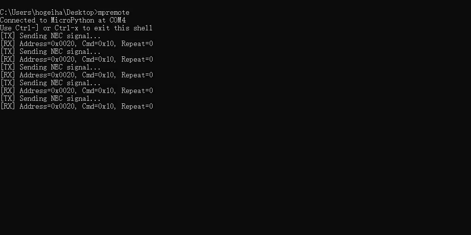
It can be seen that when the infrared receiving module based on TSOP34138 receives the data sent by the infrared transmitting module based on IR333C, it will trigger the callback function to print[RX]content.
IV. Drivers
irtranslation_driver.zip 27 KB
5. BOM & Recommended Alternative Parts
None.
VI. Revision History
Document Version | Date of Modification | Modifier | Modified Content |
v1.0 | 2025.8.20 | Miu Guicheng | Initialize the document |
v1.1 | 2025-09-18 | Li Zisheng | Added PCB routing precautions for Version 2.8 Revised Section 3, Instructions for Circuit Source Project and Module Usage, and added a secondary heading: 3.1 Circuit Source Engineering, 3.2 Module Usage Instructions, 3.3 Application Experiments The BOM sheet has not been finally checked, the driver has not been re-verified, and the 3.3 application experiment Not yet specified. |
v1.2 | 2025-12-29 | Li Zisheng | Added application experiments and production files |
v1.3 | 2025-12-31 | Xin Ruili | Create an open version of the document based on the internal document version v1.2. |
v1.4 | 2026-03-29 | Xin Ruili | Modified the application experiment section. |
VII. Relevant Materials
7.1 Chip Datasheet
TSOP34138 Infrared Receiver Datasheet.pdf 134 KB
7.2 Unique Icons for PCB Silkscreen