Contents
- I. Module Introduction
- II. Introduction to Major Chips
- 2.1 Chip Overview
- 2.2 Pin Definition
- 2.3 Functional Block Diagram
- 2.4 Performance Parameters
- 2.5 Reference Circuit
- 2.6 Chip Configuration
- 2.7 Communication Interfaces and Related Protocols
- 2.8 PCB Routing Precautions
- III. Circuit Engineering
- 3.1 Circuit Source Engineering
- 3.2 Module Usage Instructions
- 3.3 Application Experiment
- IV. Drivers
- 5. BOM & Recommended Alternative Parts
- VI. Revision History
- VII. Relevant Materials
- 7.1 Chip Datasheet
- 7.2 Unique Icons for PCB Silkscreen
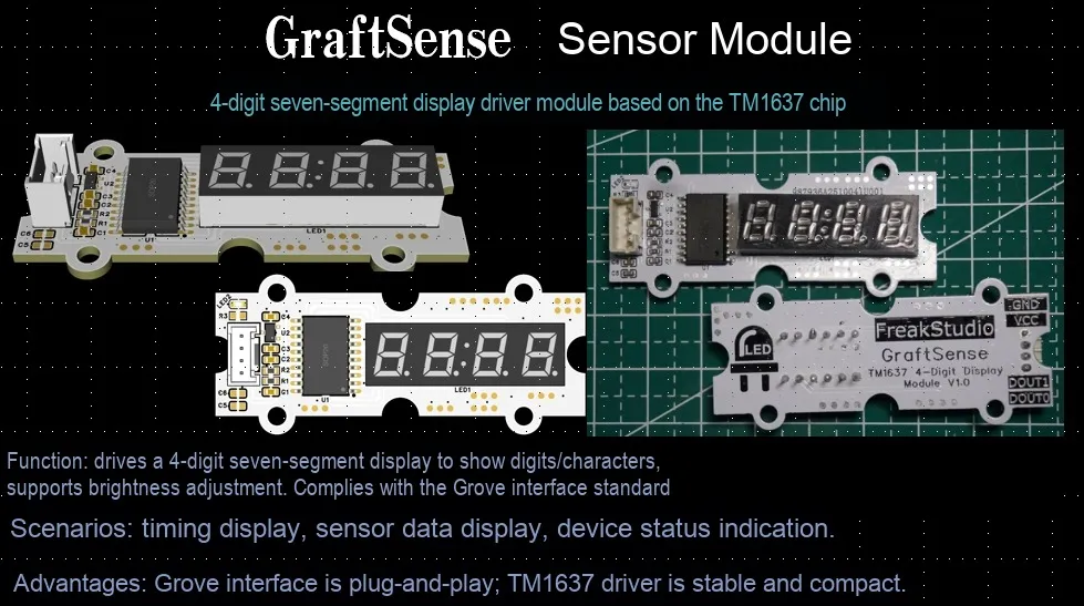
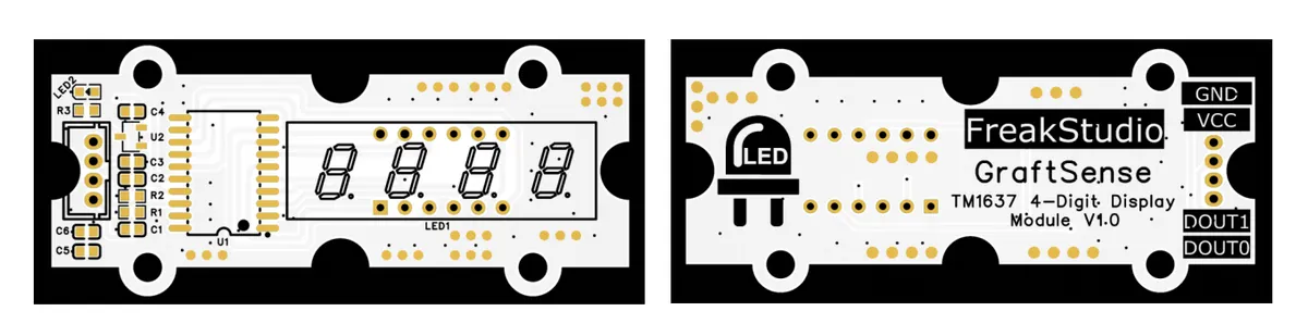
I. Module Introduction
4-digit nixie tube driver module based on TM1637 chip, which adopts the TM1637 chip to design the driving circuit for 4-digit common-anode nixie tube. It has a power input voltage of 5V, is powered by a DC-DC 5V-to-3.3V circuit, features a 3.3V communication level, and has a power consumption of about 400mW. The module communicates with the microcontroller via a two-wire serial interface, and is equipped with an MCU interface, power filtering and power indicator. It is suitable for digital display scenarios of various embedded devices, and provides a concise 4-digit digital display solution for systems.
II. Introduction to Major Chips
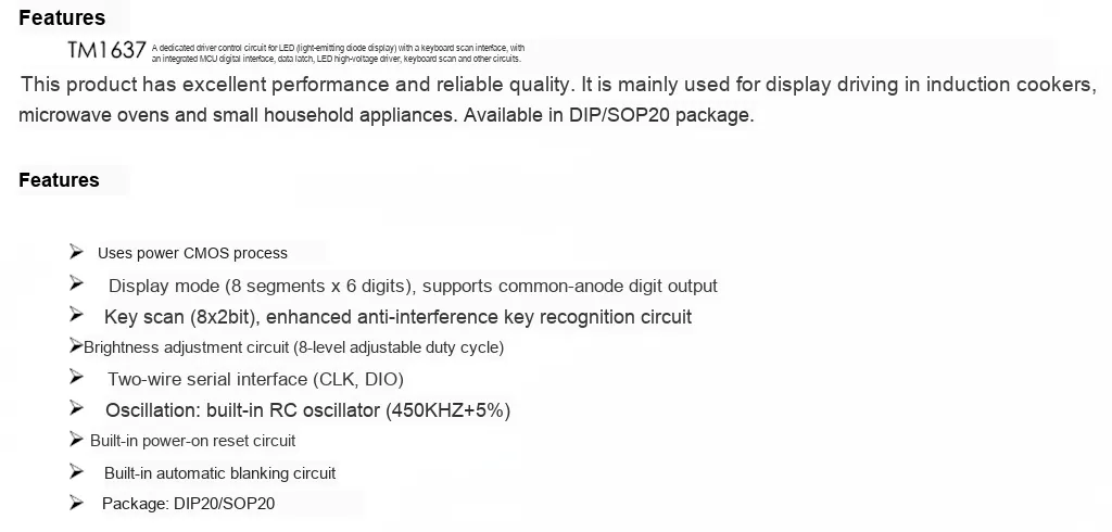
TM1637 is a highly integrated dedicated CMOS power process-based LED drive control chip, which supports 8-segment × 6-bit common-anode nixie tube output and 8×2bit key scanning, and is equipped with an enhanced anti-interference key identification circuit.It communicates via a two-wire serial interface consisting of CLK and DIO, with built-in RC oscillator, power-on reset and automatic blanking circuits, supports 8-level adjustable brightness, and is available in DIP20 / SOP20 packages. Featuring simple peripheral design, low power consumption and strong anti-interference capability, it is widely used in small household appliances and compact electronic devices requiring digital display and key interaction, such as induction cookers, electronic scales and digital clocks.
2.1 Chip Overview
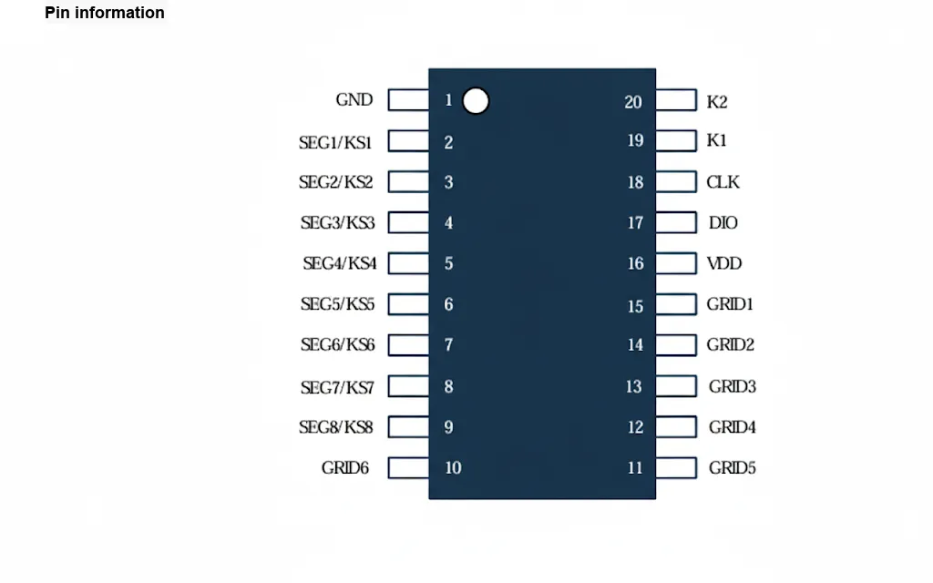
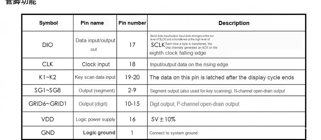
2.2 Pin Definition
2.3 Functional Block Diagram
None.
2.4 Performance Parameters
TM1637 The performance parameters are as follows:
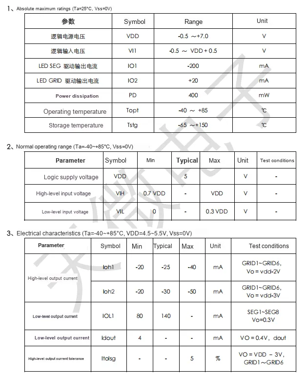
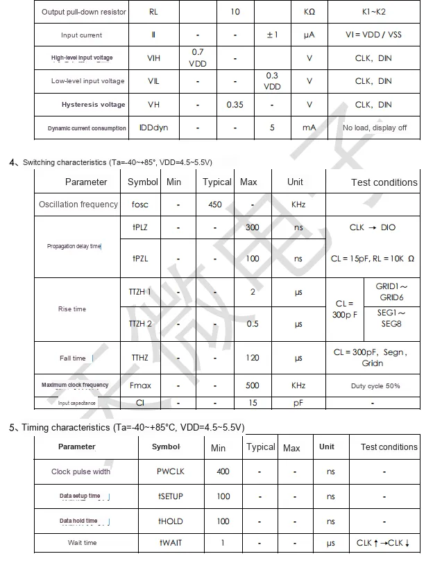
TM1637 has the following partial performance parameters:
- Timing and Frequency:
- Oscillation Frequency Typical: 450KHz;
- Transmission Delay Time Max. 300ns (CLK→DIO), 100ns (CL= 15pF, RL= 10KΩ);
- Rise Time Max. 2μs (CL= 300pF), 0.5μs (GRID1~GRID6, SEG1~SEG8);
- Rise Time Max. 120μs (CL= 300pF);
- Maximum clock frequency 500 KHz (50% duty cycle).
- Input and Output Current:
- High-level output current: lohl max. - 40mA, loh2 max. - 50mA;
- Low-level output current IOL1 min. 80mA; Idout min. 4mA;
- L ED SEG drive output current IO1 range - 200mA;
- LED GRID drive output current IO2 range + 20mA.
- Input-output Characteristics:
- Input capacitance max. 15 pF;
- Output pull-down resistor Typical: 10kΩ;
- Input current: max. ±1μA;
- High-level input voltage VIH≥0.7VDD;
- Low-level input voltage VIL ≤ 0.3VDD;
- Hysteresis voltage typically 0.35V.
- Power Supply and Power Consumption:
- Logic power supply voltage VDD range: -0.5 to + 7.0 V;
- Dynamic Current Loss Max. 5mA (no load, display off);
- Power dissipation PD max. 400 mW.
- Environment:
- Operating Temperature: -40 to + 85°C;
- Storage temperature: -65~+ 150℃.
2.5 Reference Circuit
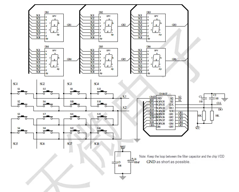
This is a multi-channel signal processing circuit, comprising 6 sets of (DS1 – DS6) detection units (each set corresponds to SG1 – SG8 signals, and is paired with an IPV module and CR1 – CR6 components). Input switching of S1 – S16 and other switches at the bottom enables input switching for SG1 – SG8, followed by signal processing via the chip. It is also equipped with auxiliary components such as power filter capacitors, for the switching, detection and processing of multi-channel signals, and is marked with the wiring requirement that the power loop of the filter capacitor and the chip should be as short as possible.
2.6 Chip Configuration
None.
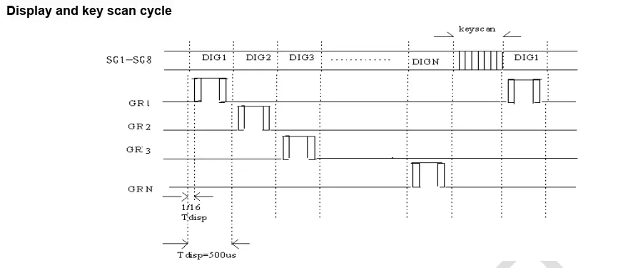
2.7 Communication Interfaces and Related Protocols
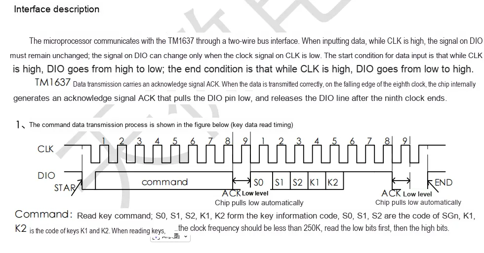
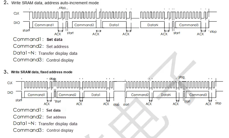
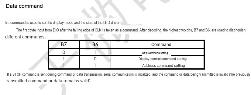
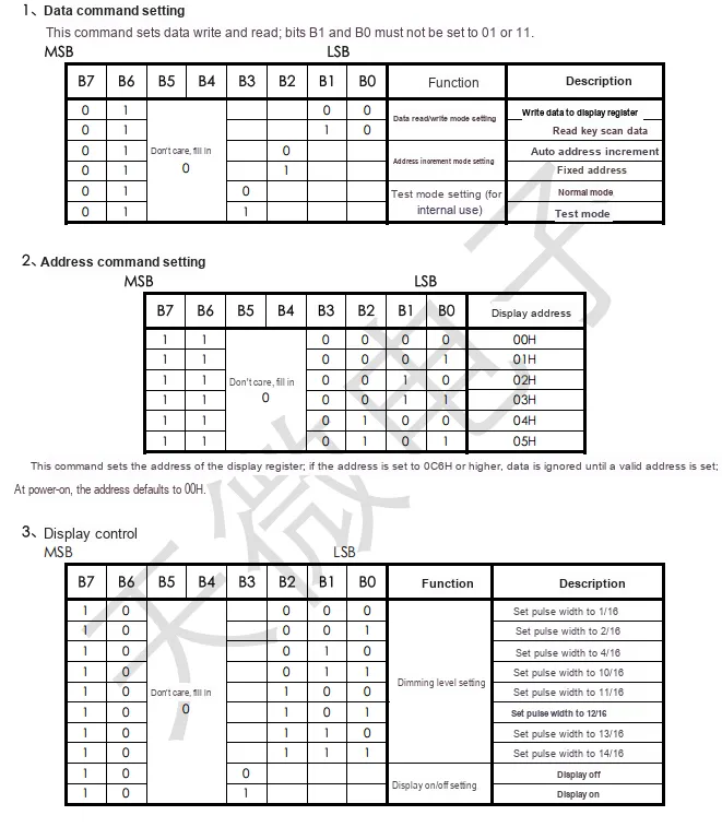
2.8 PCB Routing Precautions
None.
III. Circuit Engineering
3.1 Circuit Source Engineering
To obtain the source project of the circuit, please follow the official account [Freak Embedded]
3.2 Module Usage Instructions
SCH_Schematic1_4-Digit Display Driver Module Based on TM1637 Chip-V1.0.0_2025-11-17.pdf 3.4 MB
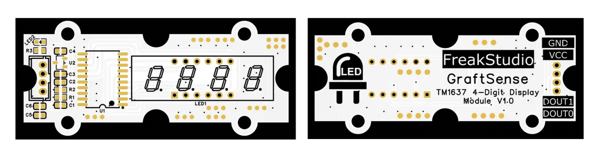
This module provides digital output communication interfaces: DOUT0 corresponds to the CLK pin of the chip, and DOUT1 corresponds to the DIO pin of the chip;It adopts a two-wire serial output format and is compatible with 3.3V/5V digital levels. DOUT0 is responsible for transmitting display data, while DOUT1 is in charge of transmitting clock synchronization signals. It can stably output character control commands, decimal point driving signals and 8-level brightness adjustment parameters for 4-bit 8-segment nixie tubes. It is suitable for scenarios such as numerical display in maker projects, status digital display of small household appliances, and counting/timing display of simple electronic devices, providing the system with accurate nixie tube display control signal output capability.
3.3 Application Experiment
Here, we use the GraftPort-RP2040 development board for testing, and connect the 4-digit digital tube driver module based on the TM1637 chip with the main controller for synchronous serial communication.
Here, we first use the HY2.0-4P cable to connect the module to the GraftPort-RP2040 development board's I2C0 interface:
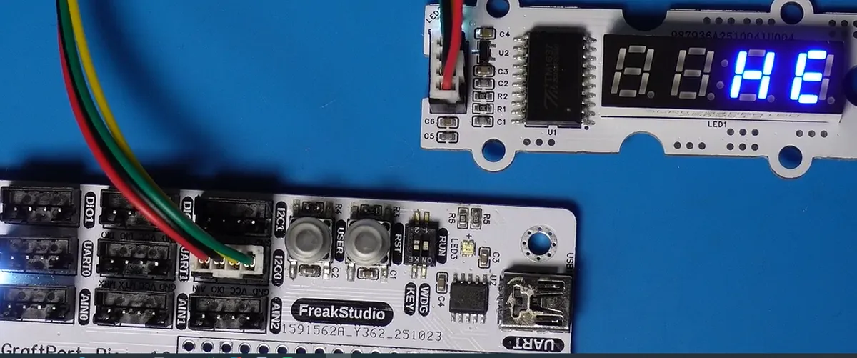
The module connections are shown in the table below:
Development Board Pins | Module Pins | Description |
Pin 4 |
|
|
Pin 5 |
|
|
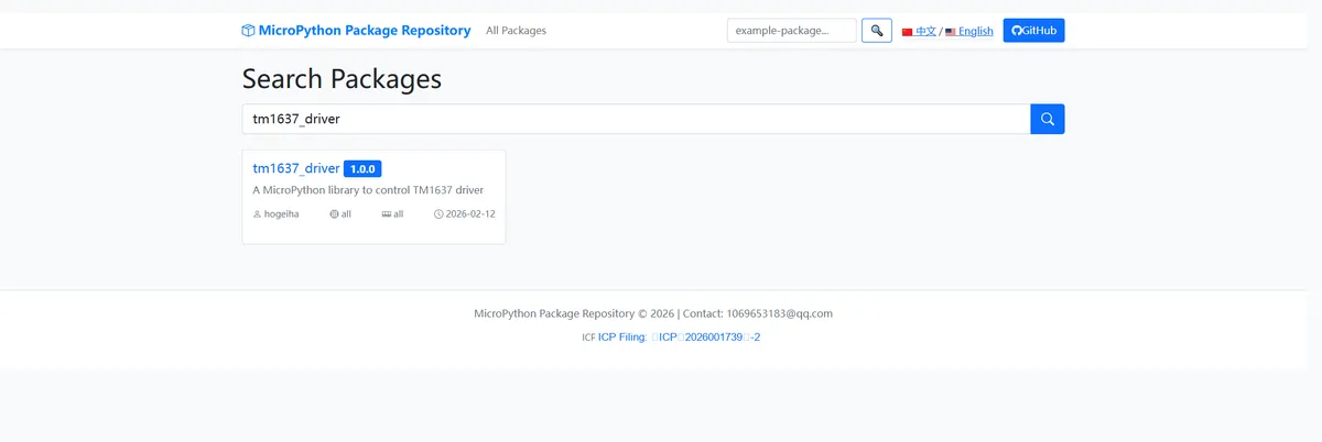
Here, we need to search for the relevant driver packages on uPyPI: https://upypi.net/zh/
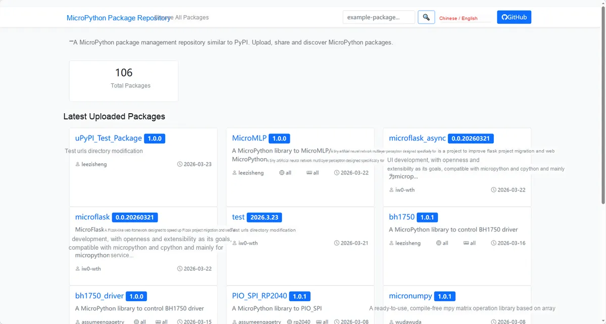
Enter tm1637_driver to search, and the following will be displayed:
Click to copy the local installation command:
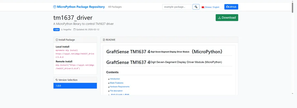
Here, we can use the mip tool to import module driver library code. The following are the usage commands for the mpremote tool:
mpremote mip install github:FreakStudioCN/GraftSense-Drivers-MicroPython/lighting/tm1637_driverImport the 4-digit digital tube driver module based on TM1637 chip - MicroPython driver code, then copy the following main.py code into our project:
# Python env   : MicroPython v1.23.0
# -*- coding: utf-8 -*-
# @Time    : 2025/01/16 10:21
# @Author  : 侯钧瀚
# @File    : main.py          # File name
# @Description : tm1637 driver example

# ======================================== Import Modules =========================================

# Import MicroPython built-in modules
from machine import Pin
# Import the tm1637 driver module
import tm1637
# Import the time module
import time

# ======================================== Global Variables ============================================

# ======================================== Functions ============================================

def demo_brightness(disp: tm1637):
    """
    Demonstrate brightness adjustment:
    Increase the brightness step by step and display the value, finally returning to a suitable brightness level.

    Args:
        disp (tm1637): display driver object.

    ==================================
    Demonstration of brightness adjustment:
    Incrementally increase brightness and display the value, then return to a suitable level.

    Args:
        disp (tm1637): Display driver object.
    """
    for b in range(0, 8):
        disp.brightness(b)
        disp.show("b{:>3d}".format(b))  # Display the current brightness
        time.sleep_ms(300)
    disp.brightness(4)
    time.sleep_ms(400)


def demo_show(disp: tm1637):
    """
    Demonstrate string display:
    Display a string and the colon display effect directly.

    Args:
        disp (tm1637): display driver object.

    ==================================
    Demonstration of string display:
    Directly display a string and show colon effect.

    Args:
        disp (tm1637): Display driver object.
    """
    disp.show("dEMo")
    time.sleep_ms(800)
    disp.show(" A01", True)
    time.sleep_ms(800)


def demo_numbers(disp: tm1637):
    """
    Demonstrate display of two groups of numbers:
    Display two groups of numbers with a colon, and demonstrate range clipping.

    Args:
        disp (tm1637): display driver object.

    ==================================
    Demonstration of dual number display:
    Display two groups of numbers with a colon, and demonstrate range clipping.

    Args:
        disp (tm1637): Display driver object.
    """
    disp.numbers(12, 34, colon=True)
    time.sleep_ms(800)
    disp.numbers(-9, 99, colon=True)
    time.sleep_ms(800)


def demo_number(disp: tm1637):
    """
    Demonstrate single number display:
    Display different integers in a loop, including positive and negative numbers.

    Args:
        disp (tm1637): display driver object.

    ==================================
    Demonstration of single number display:
    Loop through different integers, including positive and negative values.

    Args:
        disp (tm1637): Display driver object.
    """
    for n in (0, 7, 42, 256, 9999, -999, -1234):
        disp.number(n)
        time.sleep_ms(600)


def demo_hex(disp: tm1637):
    """
    Demonstrate hexadecimal number display:
    Display different hexadecimal numbers in a loop.

    Args:
        disp (tm1637): display driver object.

    ==================================
    Demonstration of hexadecimal display:
    Loop through different hexadecimal values.

    Args:
        disp (tm1637): Display driver object.
    """
    for v in (0x0, 0x5A, 0xBEEF, 0x1234, 0xFFFF):
        disp.hex(v)
        time.sleep_ms(600)


def demo_temperature(disp: tm1637):
    """
    Demonstrates temperature display:
    Cycles through different temperature values (range -15 ~ 120).

    Args:
        disp (tm1637): display driver object.

    ==================================
    Demonstration of temperature display:
    Loop through different temperature values (range -15 ~ 120).

    Args:
        disp (tm1637): Display driver object.
    """
    for t in (-15, -9, 0, 25, 37, 99, 120):
        disp.temperature(t)
        time.sleep_ms(700)


def demo_scroll(disp: tm1637):
    """
    Demonstrates string scrolling:
    Scrolls the string in a loop.

    Args:
        disp (tm1637): display driver object.

    ==================================
    Demonstration of string scrolling:
    Cyclically scroll to display the string.

    Args:
        disp (tm1637): Display driver object.
    """
    disp.scroll("HELLO TM1637  ", delay=180)


def demo_raw_write(disp: tm1637):
    """
    Demonstrates raw segment code writing:
    Uses custom segment codes to draw the middle dash, then clears it.

    Args:
        disp (tm1637): display driver object.

    ==================================
    Demonstration of raw segment writing:
    Draw middle dashes with custom segment codes, then clear.

    Args:
        disp (tm1637): Display driver object.
    """
    DASH = 0x40
    BLANK = 0x00
    disp.write([DASH, DASH, DASH, DASH], pos=0)
    time.sleep_ms(800)
    disp.write([BLANK, BLANK, BLANK, BLANK], pos=0)
    time.sleep_ms(800)


# ======================================== Custom Classes ============================================

# ======================================== Initialization ==========================================
# Power-on delay of 3 s
time.sleep(3)
# Print debug message
print("FreakStudio: Test TM1637 Module")
tm = tm1637.TM1637(clk=Pin(5), dio=Pin(4))

# ========================================  Main Program  ===========================================

while True:
        demo_brightness(tm) # Brightness goes from dim to bright and back to medium
        demo_show(tm)# Show string and colon position
        demo_numbers(tm) # Two 2-digit integers, colon lit
        demo_number(tm)# Show a single integer (range -999..9999)
        demo_hex(tm)# Hexadecimal display
        demo_temperature(tm)# Temperature display (including lo/hi)
        demo_scroll(tm) # Scrolling text
        demo_raw_write(tm)# Raw segment codes: show "----" and blank
Burn the code, open the terminal, and use the mpremote tool to connect to the main controller. The output is as follows:
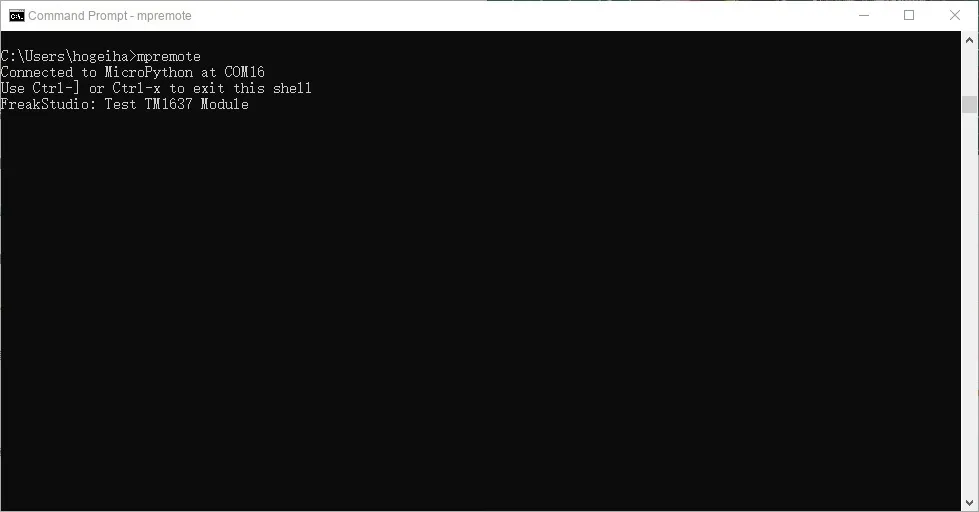
It can be seen that the digital tube performs the corresponding display:
C2056.MP4 44.0 MB
We can also enter the following commands in the REPL to test them one by one:
demo_brightness(tm) # Brightness goes from dim to bright and back to medium
demo_show(tm)# Show string and colon position
demo_numbers(tm) # Two 2-digit integers, colon lit
demo_number(tm)# Show a single integer (range -999..9999)
demo_hex(tm)# Hexadecimal display
demo_temperature(tm)# Temperature display (including lo/hi)
demo_scroll(tm) # Scrolling text
demo_raw_write(tm)# Raw segment codes: show "----" and blank
IV. Drivers
tm1637_driver.zip 12 KB
5. BOM & Recommended Alternative Parts
None.
VI. Revision History
Document Version | Date of Modification | Modifier | Modified Content |
v1.0 | 2025-11-17 | Ling Gaoxing | Initialize the document |
v1.1 | 2025-12-29 | Li Zisheng | Added application experiments and production files |
v1.2 | 2025-12-31 | Xin Ruili | Create an open version of the document based on the internal document version v1.1. |
v1.3 | 2026-03-29 | Xin Ruili | Modified the application experiment section |
VII. Relevant Materials
7.1 Chip Datasheet
TM1637 Datasheet.pdf 412 KB
7.2 Unique Icons for PCB Silkscreen