Contents
- I. Module Introduction
- II. Introduction to Major Chips
- 2.1 Chip Overview
- 2.2 Pin Definition
- 2.3 Functional Block Diagram
- 2.4 Performance Parameters
- 2.5 Reference Circuit
- 2.6 Chip Configuration
- 2.7 Communication Interfaces and Related Protocols
- 2.8 PCB Routing Precautions
- III. Instructions for Circuit Engineering and Module Usage
- 3.1 Circuit Source Engineering
- 3.2 Module Usage Instructions
- 3.3 Application Experiment
- IV. Drivers
- 5. BOM & Recommended Alternative Parts
- VI. Revision History
- VII. Relevant Materials
- 7.1 Chip Datasheet
- 7.2 Unique Icons for PCB Silkscreen
I. Module Introduction
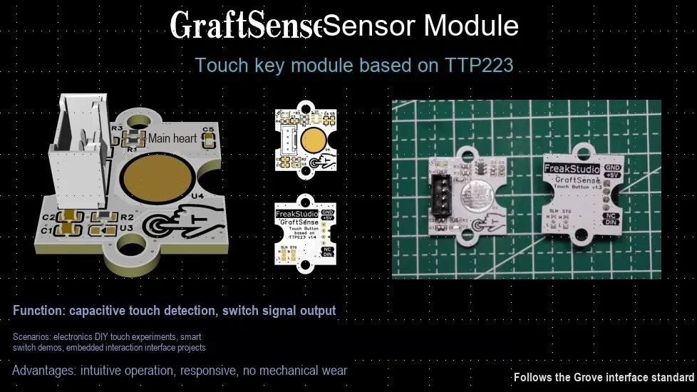
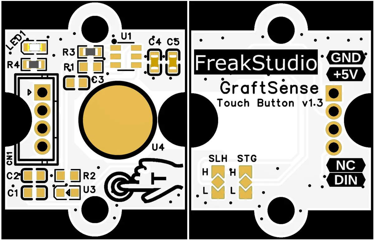
The touch key module based on TTP223 takes the TTP223-TD touch chip as the core, integrates a touch circuit, key indicator light, working mode configuration short-circuit points and power supply filtering circuit, and is equipped with GND, + 5V, NC, and DIN interfaces; different working modes of the touch key can be configured through the SLH and STG short-circuit points to realize LED signal indication and digital output after touch triggering. It is suitable for touch human-computer interaction control scenarios of embedded systems, and provides a simple and reliable touch operation solution for equipment.
II. Introduction to Major Chips
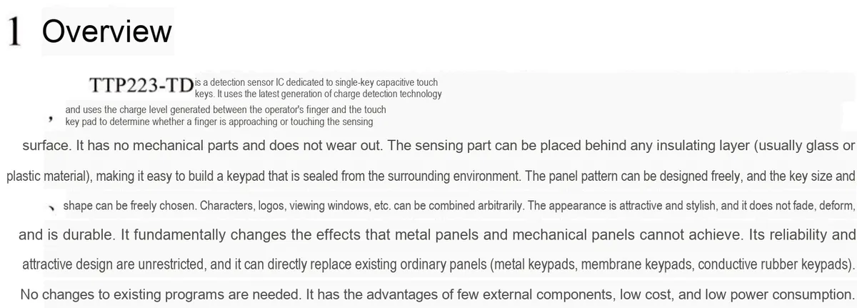
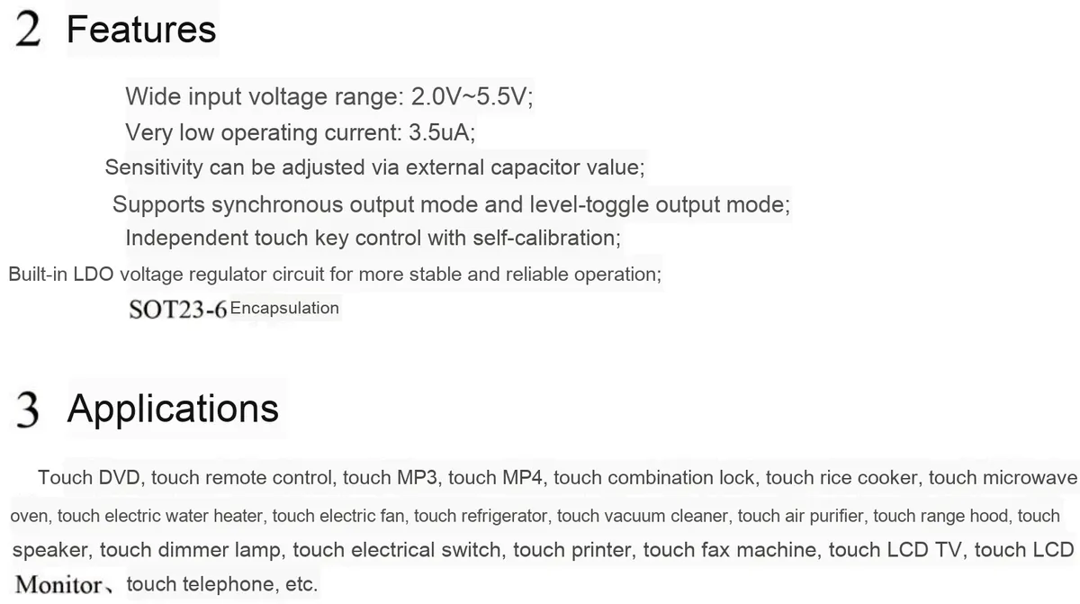
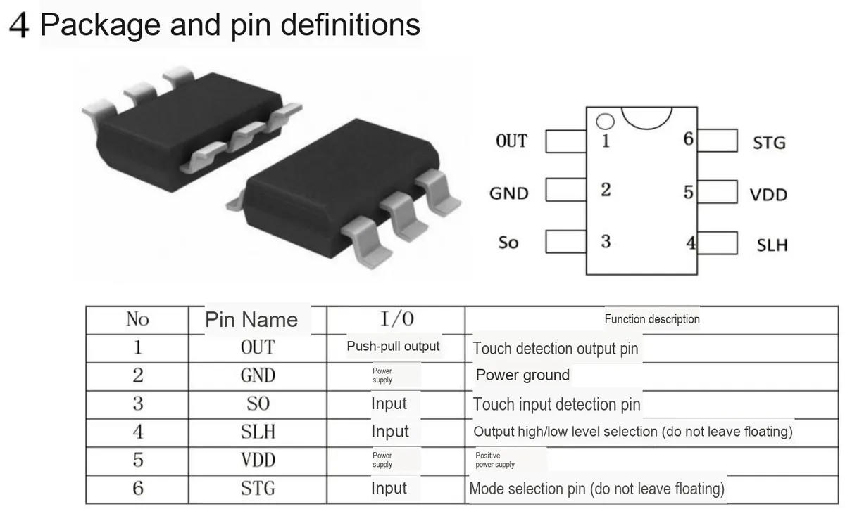
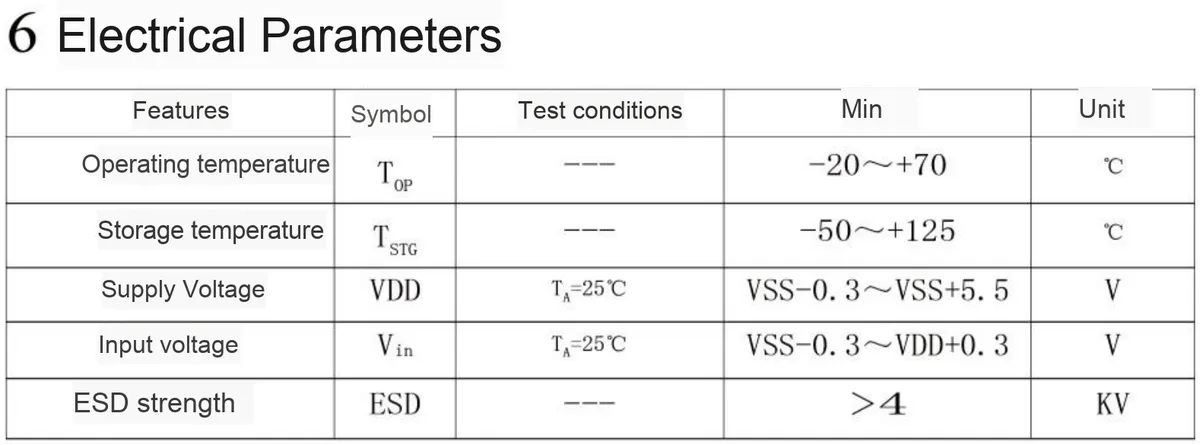
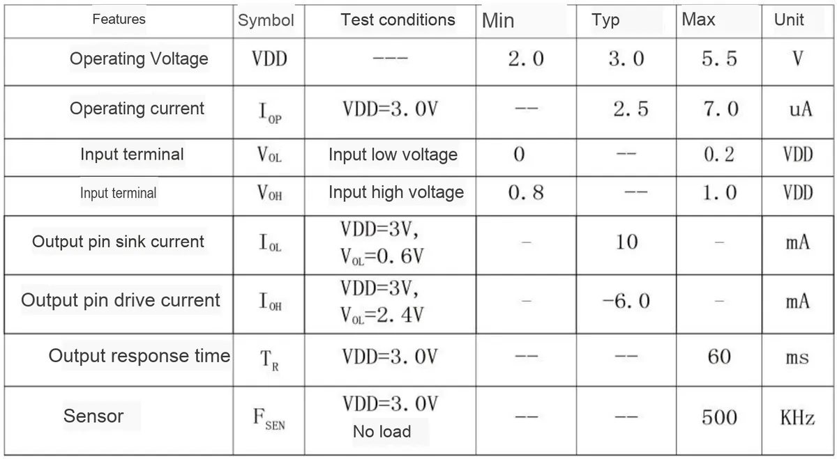
TTP223-TD is a dedicated detection sensor IC for single-key capacitive touch buttons. It adopts charge detection technology, features an input voltage range of 2.0~5.5V, extremely low operating current, and supports multiple output modes. It comes in a SOT23-6 package and can be used for human-computer interaction scenarios in numerous devices such as touch-controlled DVDs, remote controls, and home appliances. It boasts the advantages of few peripheral components, low cost, and high reliability.
2.1 Chip Overview
2.2 Pin Definition
2.3 Functional Block Diagram
None.
2.4 Performance Parameters
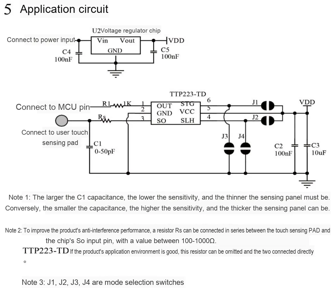
2.5 Reference Circuit
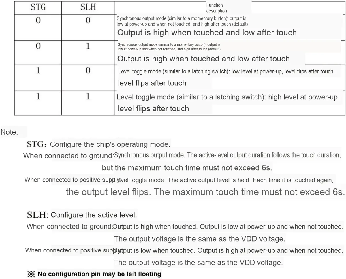
2.6 Chip Configuration
2.7 Communication Interfaces and Related Protocols
None.
2.8 PCB Routing Precautions
None.
III. Instructions for Circuit Engineering and Module Usage
3.1 Circuit Source Engineering
To obtain the source project of the circuit, please follow the official account [Freak Embedded]
3.2 Module Usage Instructions
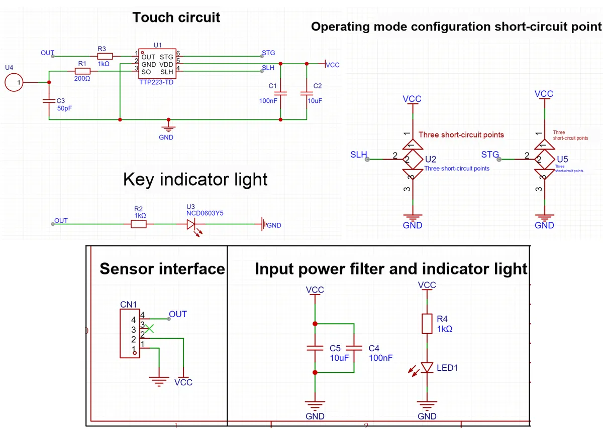
The schematic diagram of this module is shown below:
SCH_TTP223-Based Touch Button Module_v1.3_2025-09-14.pdf 1.8 MB
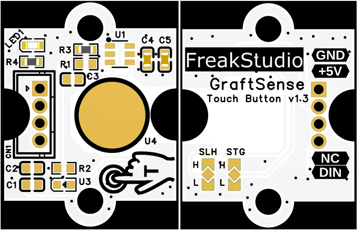
This module provides an input interface DIN: the input interface DIN needs to be connected to the MCU 's GPIO port, and users can implement four operating modes by configuring the short-circuit points of STG and SLH:
STG= 0,SLH= 0, theDINpin outputs a low level when no touch is present, and outputs a high level after a touch (synchronous touch mode);STG= 0,SLH = 1, DIN outputs a high level when there is no touch, and outputs a low level after being touched (inverting synchronous touch mode);STG= 1,SLH= 0: At power-up,DINis at low level, and the level toggles after a touch (latch mode);STG= 1,SLH= 1, the initial state ofDINis high level upon power-up, and the level toggles after a touch (inverted latch mode).
However, it should be noted here that by default, only when STG = 0 and SLH = 0, the LED of U3 will automatically light up when the user presses a key.
3.3 Application Experiment
Here, we use the GraftPort-RP2040 development board for testing, and communicate with the DIO interface on the touch button module based on TTP223 .
Here, we first use the HY2.0-4P cable to connect the module to the GraftPort-RP2040 development board's DIO0 interface:
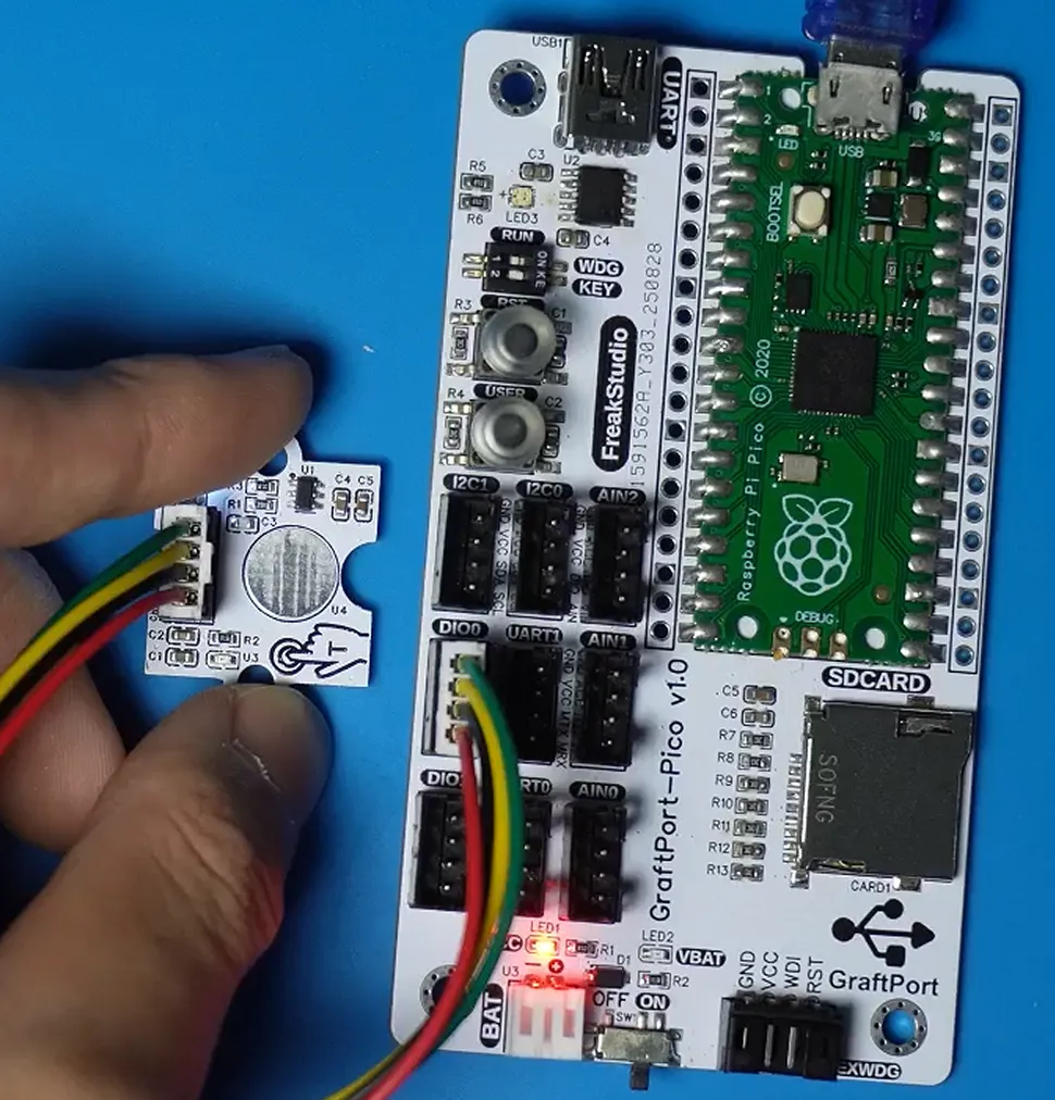
The module connections are shown in the following table:
Development Board Pins | Module Pins | Description |
Pin 6 |
| Level signal input pin after key press/release |
Pin 7 |
| - |
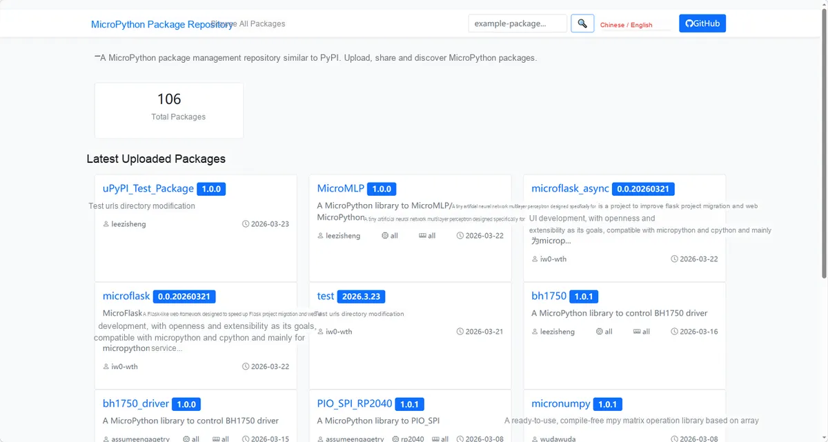
Here, we need to search for the relevant driver packages on uPyPI: https://upypi.net/zh/
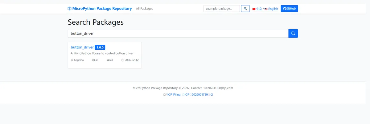
Enter button_driver to search, and the following will be displayed:
Click to copy the local installation command:
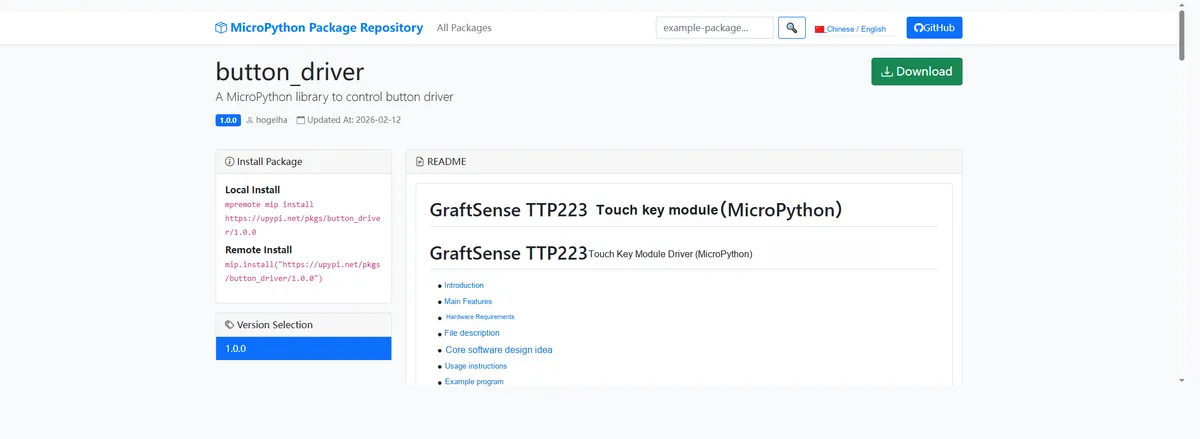
Import the module driver library code via the mip tool. Below are the usage commands for the mpremote tool:
mpremote mip install https://upypi.net/pkgs/button_driver/1.0.0After importing the key module driver - the MicroPython driver code, copy the following main.py code into our project:
# Python env   : MicroPython v1.23.0
# -*- coding: utf-8 -*-
# @Time    : 2025/8/28 AM 11:22
# @Author  : ben0i0d
# @File    : main.py
# @Description : Touch key driver test file

# ======================================== Import Modules =========================================

# Import time-related modules
import time
# Import the button driver module
from touchkey import TouchKey

# ======================================== Global Variables ============================================

# ======================================== Functions ============================================

def on_press():
    print("Button pressed")

def on_release():
    print("Button released")

# ======================================== Custom Classes ============================================

# ======================================== Initialization configuration ===========================================

# Power-on delay of 3 s
time.sleep(3)
print("FreakStudio:Testing Button")

# Create TouchKey object
button = TouchKey(pin_num=15, idle_state=TouchKey.high, debounce_time=50, press_callback=on_press, release_callback=on_release)

# ========================================  Main Program  ============================================

try:
    while True:
        state = button.get_state()
        print("Current button state:", "Pressed" if state else "Released")
        time.sleep(0.5)

except KeyboardInterrupt:
    print("Exit button test program")
Burn the code, open the terminal, and use the mpremote tool to connect to the main controller. The output is as follows:
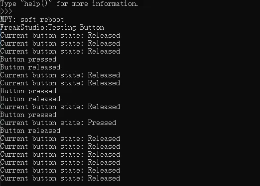
It can be seen that when we touch the pad in the middle of the module, the terminal will print the status of the touch button.
IV. Drivers
button_driver.zip 9 KB
5. BOM & Recommended Alternative Parts
None.
VI. Revision History
Document Version | Date of Modification | Modifier | Modified Content |
v1.0 | 2025-08-13 | Miu Guicheng | Initialize the document |
v1.1 | 2025-11-03 | Li Zisheng | Added PCB routing precautions for Version 2.8 Revised Section 3, Instructions for Circuit Source Project and Module Usage, and added a secondary heading: 3.1 Circuit Source Engineering, 3.2 Module Usage Instructions, 3.3 Application Experiments The BOM sheet has not been finally checked, the driver has not been re-verified, and the 3.3 application experiment Not yet specified. |
v1.2 | 2025-12-29 | Li Zisheng | Added application experiments and production files |
v1.3 | 2025-12-31 | Xin Ruili | Create an open version of the document based on the internal document version v1.2. |
v1.4 | 2026-03-29 | Xin Ruili | Modified the application experiment section |
VII. Relevant Materials
7.1 Chip Datasheet
C42422128_Touch Chip_TTP223-TD_Datasheet_TTP223-TD.PDF 724 KB
7.2 Unique Icons for PCB Silkscreen