Contents
- I. Pin Mapping
- 1.1 Fixed Hardware Pin Mapping
- 1.2 SD Card SPI Interface Configuration
- 1.3 Peripheral Interface Pin Mapping
- II. BOM & Recommended Alternative Parts
- III. Relevant Software and Hardware Tutorials
- 3.1 MicroPython Environment Configuration and Firmware Flashing
- 3.2 MicroPython Driver Development and Code Writing
- 3.3 Usage of Various Electronic Modules
- 3.4 View Relevant Teaching Cases
- 3.5 View Related to Network Communication
- IV. Circuit Source Engineering
- 5. Driver Code
- 5.1 Environment Preparation
- 5.2 Description of Code Package Contents
- 5.3 Procedure
- VI. Revision History
- VII. Relevant Materials
- 7.1 Chip-related Materials
- 7.2 PCB Special Silk Screen Printing
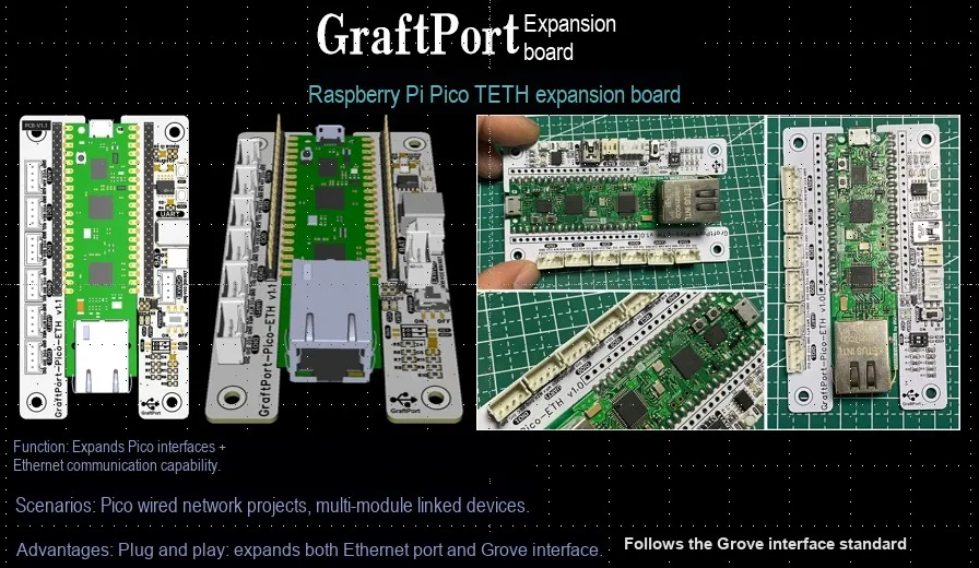
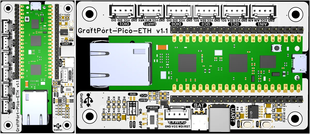
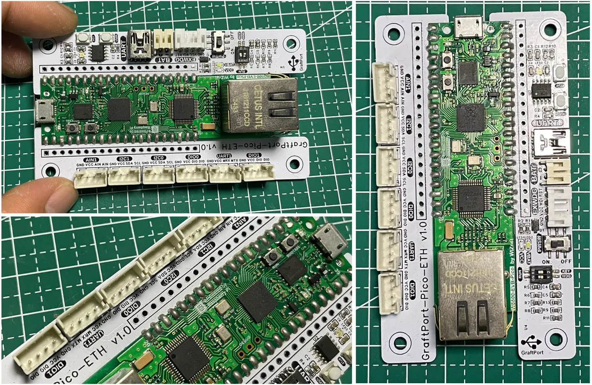
GraftPort - Raspberry Pi Pico-ETH Expansion Board is a functional expansion board designed for the Raspberry Pi Pico. Built around the WIZnet-EVB-Pico (2)(which integrates a WIZnet Ethernet controller), it can quickly extend networking capabilities and support for multiple types of peripherals for the Pico, making it ideal for IoT and embedded control projects.
Its core features include:
- Network Capability: Relying on the Ethernet function of the WIZnet Ethernet controller, it supports wired network communication and enables remote data transmission as well as networked device control.
- Abundant Interfaces: Equipped with multiple sets of Grove standardized interfaces (including 2×I2C, 1×UART, 2×digital interfaces, 1×analog interface) and an external watchdog interface, it is compatible with Grove ecosystem peripherals for more convenient wiring.
- Practical Modules: Integrated with a MicroSD storage module (for storing project data and firmware), reset/user buttons, and multiple status indicators; it also comes with a built-in CH340K serial port unit to facilitate computer-side debugging.
- Flexible Power Supply and Expansion: Supports VBAT battery power supply + external power input, and can be further expanded with more functional modules via the GraftPort expansion interface.
I. Pin Mapping
Note: All pin number descriptions in this document follow the arrangement of the Pico (2) series. If some pin numbers on your development board are different, please refer to the pinout diagram of W5500-EVB-Pico we provided for verification.
1.1 Fixed Hardware Pin Mapping
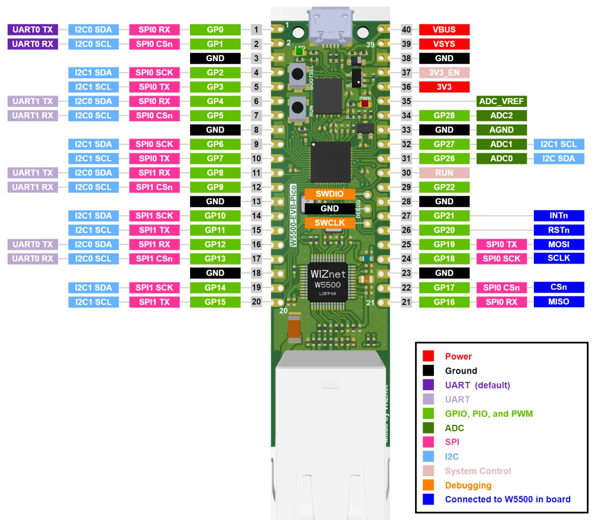
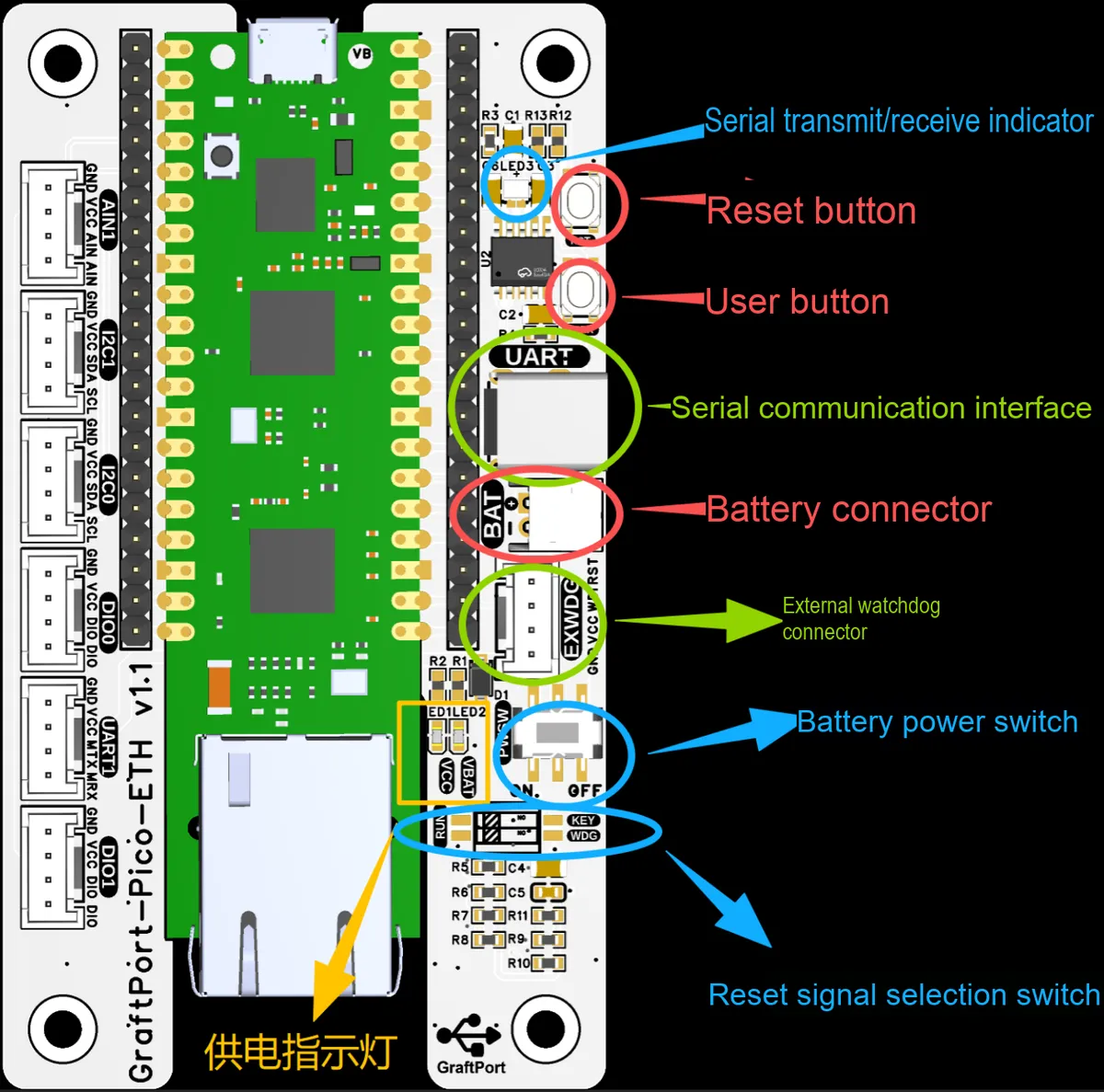
This part refers to the fixed (non-modifiable) connection between the expansion board and the Raspberry Pi Pico (or other development boards compatible with Pico pins), covering the core on-board hardware functions:(for development boards that are compatible with Pico but have different pin numbers, please refer to the above figure for comparison on your own)
| I/O | Pin Name | Description |
| I | GPIO24 | VBUS detection pin: high when VBUS is present, otherwise low |
| O | GPIO25 | Connected to the onboard user LED |
| I | GPIO29 | Samples the VSYS/3 voltage in ADC mode (ADC3) |
| I | GPIO26 | Connected to the onboard user button |
| O | GPIO22 | Connected to WATCHDOG_WDI (watchdog feed pin) |
Of course, the development board itself may also have fixed pins. Here, we take the W5500-EVB-Pico as an example.
| I/O | Pin Name | Description |
| I | GPIO16 | Connected to the MISO pin of the W5500 |
| O | GPIO17 | Connected to the CSn pin of the W5500 |
| O | GPIO18 | Connected to the SCLK pin of the W5500 |
| O | GPIO19 | Connected to the MOSI pin of the W5500 |
| O | GPIO20 | Connected to the RSTn pin of the W5500 |
| I | GPIO21 | Connected to the INTn pin of the W5500 |
However, this is not strongly related to the expansion board itself. Please refer to the documentation of your own development board.
Here, we can use the RUN DIP switch to select whether the reset signal comes from the on-board button or the watchdog module externally connected to the EXWDG header.
1.2 SD Card SPI Interface Configuration
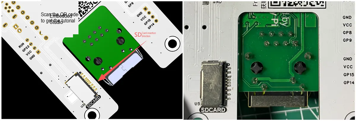
The onboard MicroSD card communicates via the SPI protocol, and the pin configuration and circuit information are as follows:
| Configuration item | Value / Pin | Notes |
| SPI_ID | 1 | SPI controller number used |
| SCLK | GP10 | SD card SPI clock pin, with a 10kΩ pull-up resistor to +3V3 |
| MOSI | GP11 | SD card SPI master output pin, with a 10kΩ pull-up resistor to +3V3 |
| MISO | GP12 | SD card SPI master input pin, with a 10kΩ pull-up resistor to +3V3 |
| CS | GP13 | SD card SPI chip select pin (active low), with a 10kΩ pull-up resistor to +3V3 |
1.3 Peripheral Interface Pin Mapping
The interfaces in this part are extensible peripheral interfaces, which support the connection of external devices such as sensors and modules, and are classified by interface type as follows.
1.3.1 I2C Interface
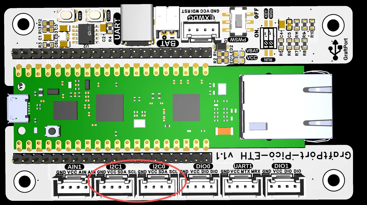
It supports 2-channel I2C interfaces, which can be used to connect peripherals compliant with the I2C protocol (such as temperature and humidity sensors, OLED displays, etc.).
I2C ID | SDA pin | SCL pin | Remarks |
I2C0 | 4 | 5 | Channel 1 I2C interface |
I2C1 | 2 | 3 | I2C Interface, Channel 2 |
1.3.2 UART Interface
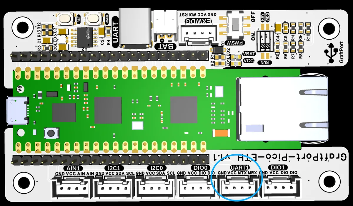
It supports 1-channel UART interface, which can be used for serial communication (e. g. connecting GPS modules, Bluetooth modules, etc.).
UART Number | TX pin | RX pin | Remarks |
UART1 | 8 | 9 | Channel 1 UART Communication Interface |
1.3.3 Digital Input/Output (DIO) Interface
Supports 2 sets of digital IO interfaces for digital signal input/output (e. g., relay control, key reading):
| Digital interface label | DIO pin 1 | DIO pin 2 | Interface number | Notes |
| DIO0 | GP6 | GP7 | CN3 | Silkscreen label "DIO0", includes GND and +5V power pins |
| DIO1 | GP14 | GP15 | CN6 | Silkscreen label "DIO1", includes GND and +5V power pins |
1.3.4 ADC Interface
Supports 1 analog interface for collecting analog signals such as voltage and illuminance:
| Interface label | Pin combination | Notes |
| AIN1 | (GP27, GP28) | Includes ADC1_PIN (GP27) and ADC2_PIN (GP28) |
II. BOM & Recommended Alternative Parts
None
III. Relevant Software and Hardware Tutorials
3.1 MicroPython Environment Configuration and Firmware Flashing
Here only the W5500-EVB-Pico firmware is provided as an example. For other development boards, please refer to their respective documentation on your own.
- MicroPython Firmware Download: https://micropython.org/download/W5500_EVB_PICO/
W5500_EVB_PICO-20251209-v1.27.0.uf2 1.0 MB
View:
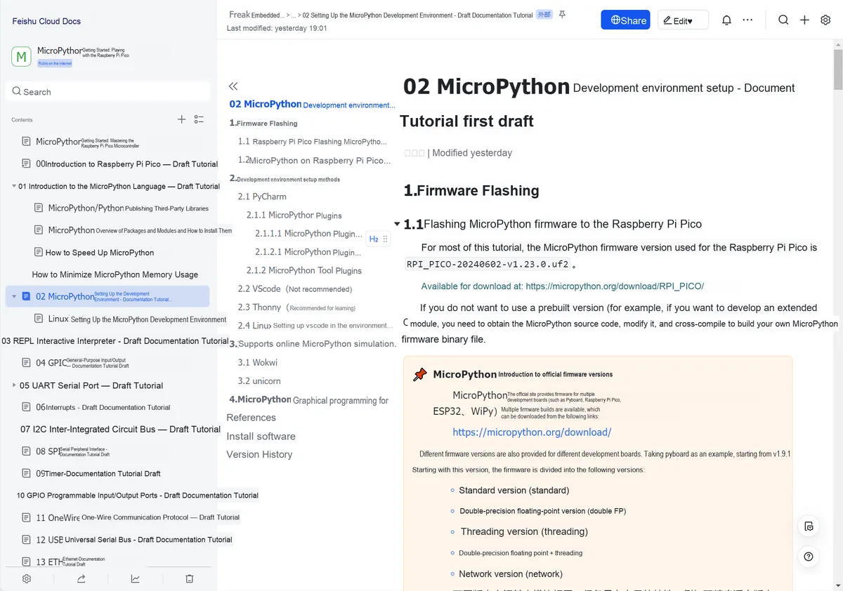
01 Introduction to MicroPython Language — Draft Document Tutorial
02 Setting up the MicroPython Development Environment — Draft Document Tutorial
3.2 MicroPython Driver Development and Code Writing

3.3 Usage of Various Electronic Modules
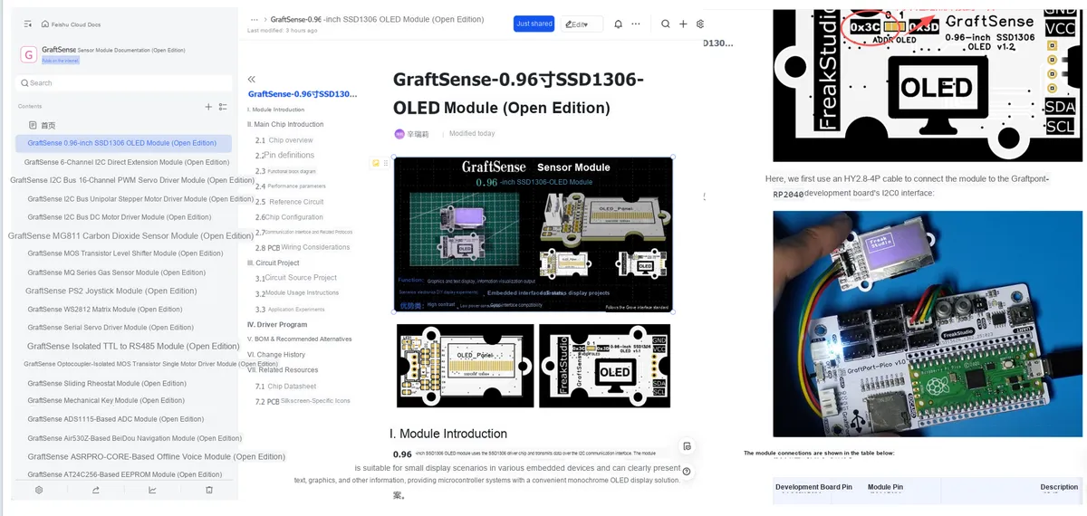
View: GraftSense Sensor Module Documentation (Open Version)
3.4 View Relevant Teaching Cases
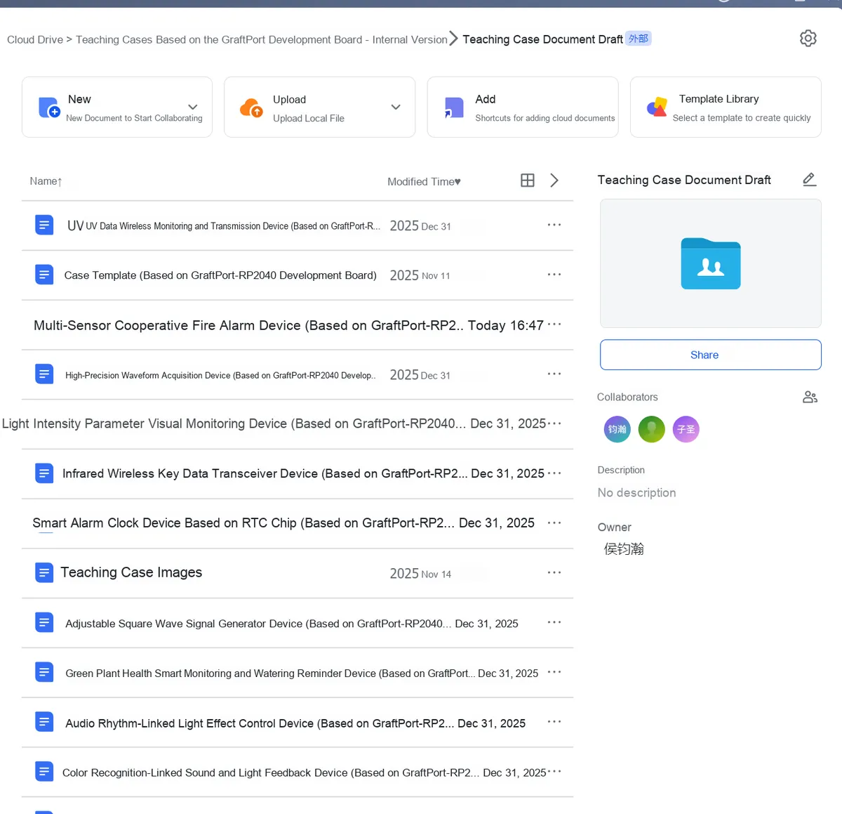
View: https://f1829ryac0m.feishu.cn/drive/folder/NzISfP3xMlPdGfdPzjEcEfjAntb? from= from_copylink
3.5 View Related to Network Communication
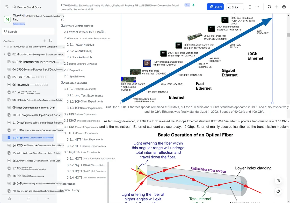
View: 13 ETH Ethernet - Document Tutorial Draft
IV. Circuit Source Engineering
To obtain the source project of the circuit, please follow the official account [Freak Embedded]
SCH_GraftPort-Raspberry Pi Pico-ETH Expansion Board_v1.1_2025-12-29.pdf 832 KB
5. Driver Code
The following is the code for quickly testing the functions of the expansion board:
- SD Card Read/Write Test:
- Initialize the SPI interface corresponding to the Micro-SD card slot of the expansion board;
- Create a file at
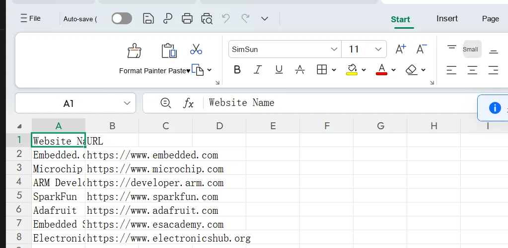
/sdcard/embedded_websites.csvin the SD card, and write the list of embedded learning websites into it.
- UART Serial Port Test:
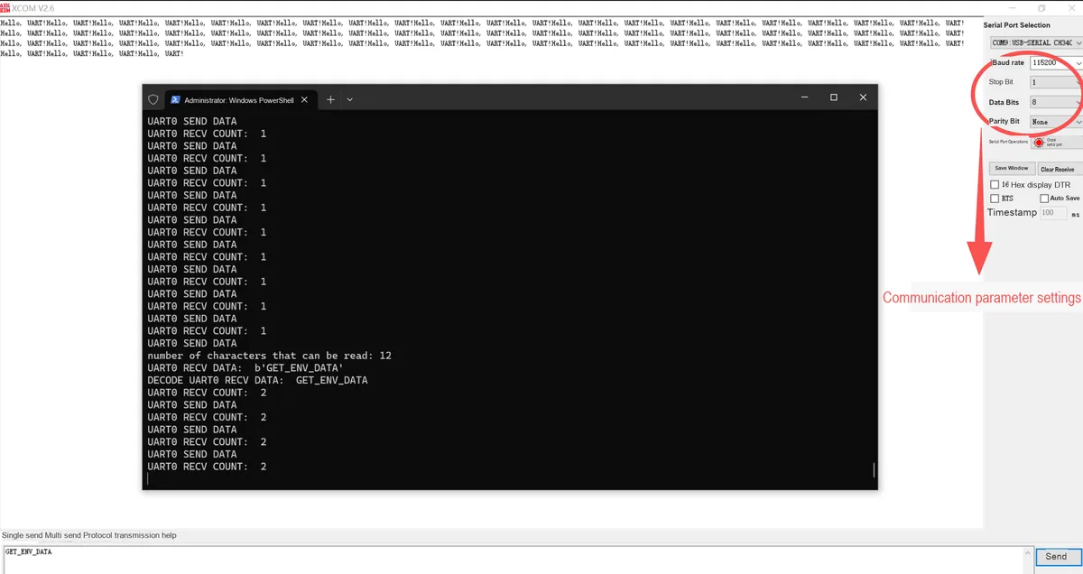
- Initialize the UART0 interface of the expansion board (baud rate: 115200);
- Loop to send data to the UART and monitor for incoming data at the same time, and stop the serial communication after completing a total of 10 rounds of data transmission and reception.
- Onboard LED Control:
- When the serial port receives data, the onboard LED will light up as a status indicator;
- After completing 10 serial transmission and reception cycles, the LED enters a blinking mode with a 100ms interval to indicate that the program has stopped running.
5.1 Environment Preparation
- Local Python version: Python 3.12.0 needs to be installed Python 3.12.0 (consistent with the code Development Environment);
- Dependency Tool Installation: Run the following command in the terminal to install the code compile and upload tools:
pip install mpy-cross mpremote5.2 Description of Code Package Contents
Here, you only need to extract the following folder:
01 Driver Code.rar 22 KB
Use PyCharm to open the following folder:
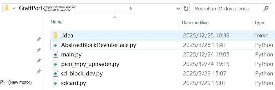
The folder contains the following core files:
| File Name | Function description |
| pico_mpy_uploader.py | Compile + upload tool: automatically compiles Python files other than main.py to mpy format (saves Pico storage space) and uploads all files to the Pico |
| main.py | Expansion board test main program: verifies SD card read/write, UART serial send/receive, and onboard LED control |
| sd_block_dev.py/sdcard.py | SD card dependency class: provides low-level support for SD card block device operations, file system mounting, and read/write |
| AbstractBlockDevInterface.py | Block device interface abstract class: provides a unified operation interface template for SD card block devices |
5.3 Procedure
Here, you first need to SD card into the SDCARD slot on the expansion board, then connect the Raspberry Pi Pico to your computer via USB, open the extracted folder, and run pico_mpy_uploader.py — the script will automatically complete the following steps:
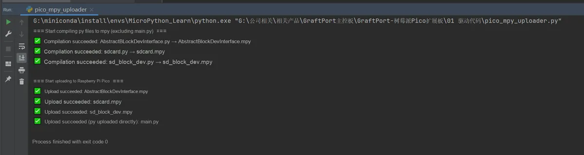
- compile non-
main.pyPython files into mpy format; - Upload the compiled
mpyfiles andmain.pyto the Pico; - After the upload is complete,
Picowill automatically runmain.pyto start the test.
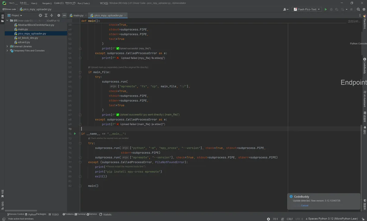
After running, the terminal displays the following:
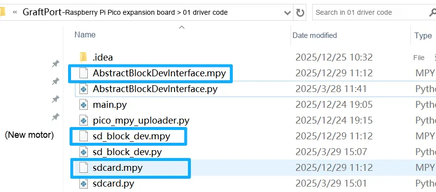
We can see that there are additional compiled mpy files in the folder:
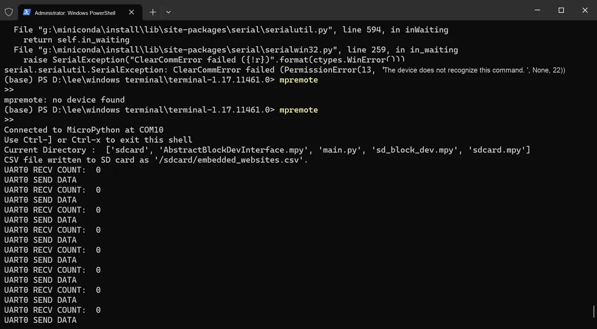
Next, reset the microcontroller unit, open the terminal, and connect to the Raspberry Pi Pico via mpremote:
Next, use a MiniUSB cable to connect the UART interface on the expansion board to a computer, open XCOM to verify whether its serial communication works properly:
Then connect the SD card to the computer via a card reader, and you can see that the CSV file has been written successfully:

VI. Revision History
Document Version | Date of Revision | Modifier | Modify Content |
v1.0.0 | 2025-09-11 | Li Zisheng | Draft the document. |
v1.0.1 | 2026-01-04 | Li Zisheng | Modify document title |
v1.1.0 | 2026-01-04 | Li Zisheng | Created based on internal version v1.0.1. |
VII. Relevant Materials
7.1 Chip-related Materials
- Raspberry Pi Pico: https://pico.nxez.com/getting-started/
- Raspberry Pi Pico Series Resources: https://pidoc.cn/docs/microcontrollers/pico-series/
- W5500-EVB-Pico Development Board: https://wiznet.io/products/evaluation-boards/w5500-evb-pico
- https://docs.wiznet.io/Product/Chip/Ethernet/W5500/w5500-evb-pico
- https://docs.wiznet.io/Product/Chip/Ethernet/W5500/w5500-evb-pico
- MicroPython Firmware Download: https://micropython.org/download/W5500_EVB_PICO/
W5500-EVB-Pico_V100.zip 3.4 MB
W5500-EVB-Pico_PL_V100.pdf 49 KB
W5500-EVB-Pico_GB_V100_Single.zip 527 KB
W5500-EVB-Pico_SCH_V100.pdf 871 KB
W5500_EVB_PICO-20251209-v1.27.0.uf2 1.0 MB
7.2 PCB Special Silk Screen Printing