
Contents
- 1. Hardware Explanation
- 1.1 Introduction to ETH Ethernet Protocol
- 1.2 Introduction to the W5500 Ethernet Module
- 2. Software Control Method
- 2.1 Firmware Flashing for Wiznet W5500-EVB-Pico
- 2.2 Methods Related to Ethernet Communication Category
- 2.3 Debugging Software Download
- 2.4 Preparations
- 2.5 Special Notes
- 3. Application Examples
- 3.1 TCP Protocol Experiment
- 3.2 UDP Protocol Experiment
- 3.3 DHCP Protocol Experiment
- 3.4 DNS Protocol Experiment
- 3.5 HTTP Protocol Experiment
- 3.6 MQTT Protocol Experiment
- References
- Version Record
1. Hardware Explanation
1.1 Introduction to ETH Ethernet Protocol
1.1.1 Introduction to ETH Ethernet Protocol
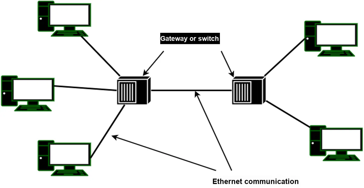
Before Wi-Fi became widespread, Ethernet was the standard way to connect devices. By running Ethernet cables within a Local Area Network (LAN) or Wide Area Network (WAN), we could transmit data back and forth between different Ethernet-enabled devices:
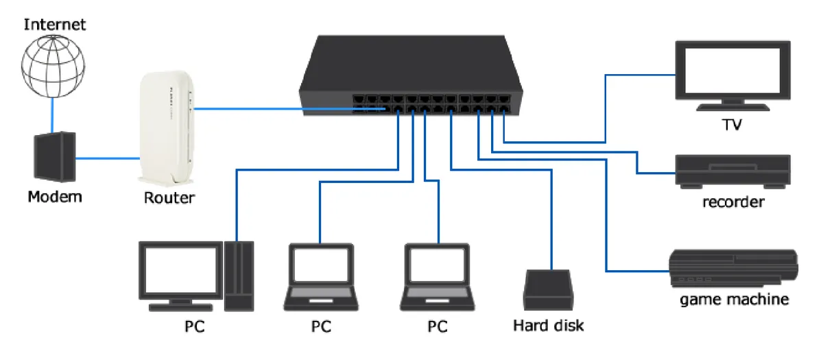
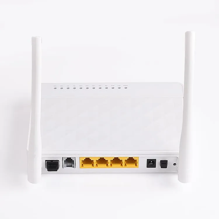
At home, the most common Ethernet connection solution is that users connect the optical network unit to the ISP (Internet Service Provider) via optical fiber; the optical network unit is connected to the router or switch in the home network through a network cable (usually with an RJ45 interface); other devices (such as computers, smart TVs, game consoles, etc.) connect to the router or switch via network cable or wireless means to access the Internet.
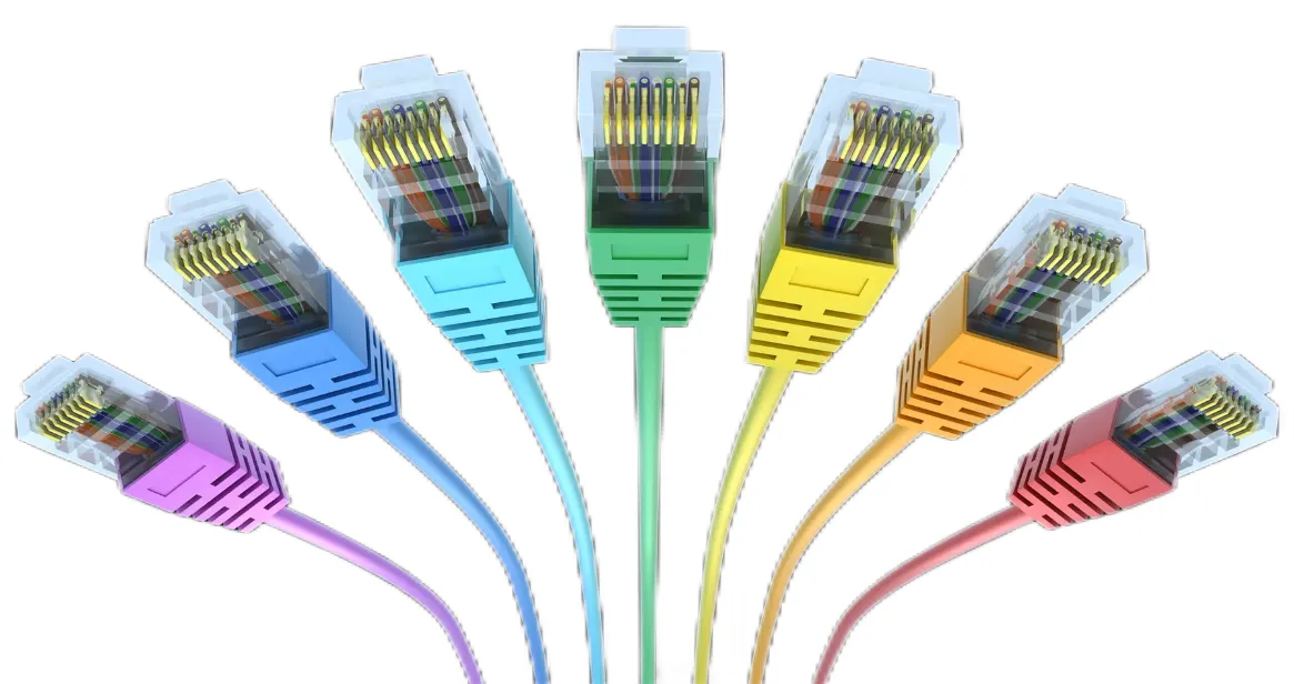
Ethernet is a widely adopted wired local area network (LAN) technology that forms the foundation of the IEEE 802.3 standard series. Its fundamental operating principle is as follows: data is transmitted among multiple nodes on the network, with communication between nodes carried out via media such as copper cables or optical fiber channels. Each node is assigned a unique identifier, namely the MAC (Media Access Control) address, which is a 48-bit array typically represented in hexadecimal format, for example, 00:11:22:33:44:55. Ethernet boasts the following key characteristics:
- Physical Layer Technology:
- Adopt a bus topology
- Adopt the CSMA/CD (Carrier Sense Multiple Access with Collision Detection) media access control mechanism
- Supports different transmission rates such as 10Mbps, 100Mbps, and 1000Mbps
- Data Link Layer Protocol:
- defines the format and data encapsulation method of Ethernet frames
- including functions such as MAC address addressing and error detection
- Network interconnection devices:
- An Ethernet switch is used to implement interconnection at the network layer.
- Ethernet Network Interface Card (NIC) is used to connect a host to an Ethernet network
- Application Scenarios:
- Applicable to small and medium-sized local area network environments
- Widely used in network environments such as enterprises, campuses, and homes
- Development History:
- Original 10Mbps Ethernet
- It later evolved into Fast Ethernet with a speed of 100Mbps
- The current mainstream is Gigabit Ethernet at 1000Mbps
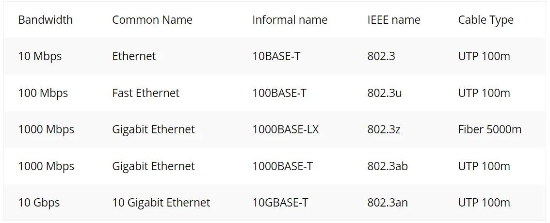
Here, we have compiled information including the communication rates, adopted standards and names of different types of Ethernet:
1.1.2 Development History of Ethernet (ETH)
Ethernet was created in the early 1970s at Xerox Palo Alto Research Center (PARC) by a team including David Boggs and Robert Metcalfe. In 1983, the Institute of Electrical and Electronics Engineers (IEEE) approved it as a new communication standard.




In late 1972, Robert Metcalfe and his colleagues at Xerox PARC developed the first experimental Ethernet system to interconnect the Xerox Alto, a personal workstation equipped with a graphical User Interface. This experimental Ethernet was used to link Altos to one another, as well as to servers and laser printers. The signal clock for the experimental Ethernet interface was derived from the Alto's system clock, which resulted in a data transmission rate of 2.94 Mbps over the experimental Ethernet.The first experimental network built by Robert Metcalfe was called the Alto Aloha Network.

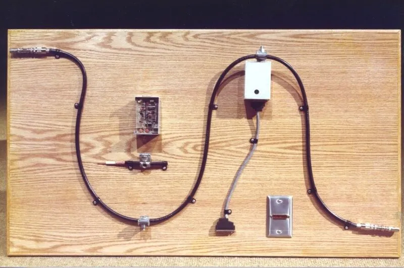
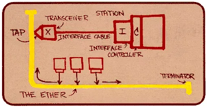
In a document written by Robert Metcalfe for Xerox PARC in 1973, he put forward the concept of Ethernet, marking the start of Ethernet development. In that document, Robert Metcalfe renamed the experimental Ethernet from the Alto Aloha Network to Ethernet, to make it clear that this system could support any type of computer, and pointed out that the development of his new network mechanism went far beyond the Aloha System.He chose the term "ether" as the basis for the name to describe the fundamental characteristic of the system: a physical medium (i. e., a cable) that carries data bits to all stations, much like the old "luminiferous ether" once thought to propagate electromagnetic waves through space. In 1976, Robert Metcalfe and his assistant David Boggs formally published a paper on Ethernet technology titled "Ethernet: Distributed Packet Switching for Local Computer Networks".
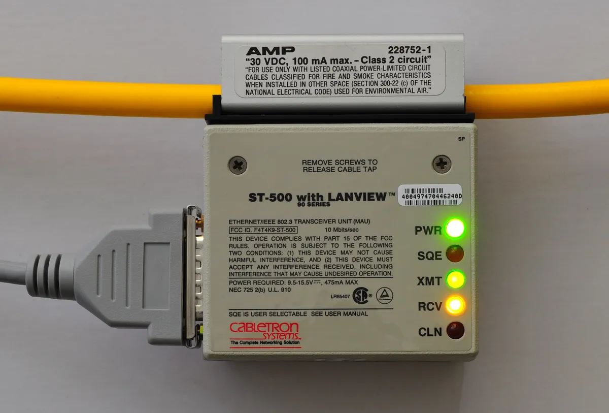
In 1982, Xerox, DEC and Intel formed the DIX consortium, jointly released the specification for Ethernet Version 2 (EV2), brought it to the commercial market, where it gained widespread adoption. The EV2 network is the currently IEEE-recognized 10BASE5, which uses thick coaxial cable as the physical medium, supports a maximum transmission distance of 500 meters and operates at a transmission rate of 10 Mbps.Ethernet technology achieved tremendous success in the market, so much so that in December 1978, Intel and Xerox reached an agreement on the universal 10Mb/s Ethernet standard DIX, which became the IEEE 802.3 standard in 1983.
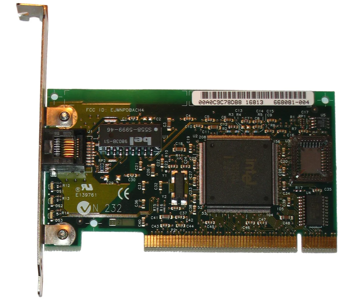
In 1995, the IEEE released the Fast Ethernet standard that supports a transmission speed of up to 100Mbps. Compared with the traditional 10Mbps Ethernet, Fast Ethernet has achieved significant improvements in data transmission speed and performance, while still maintaining the compatibility and stability of Ethernet.
In 2002, IEEE further released the Gigabit Ethernet standard, namely IEEE 802.3ab, which supports a transmission rate of 1Gbps. Gigabit Ethernet can use optical fibers, Category 5 or higher twisted pair cables as transmission media.
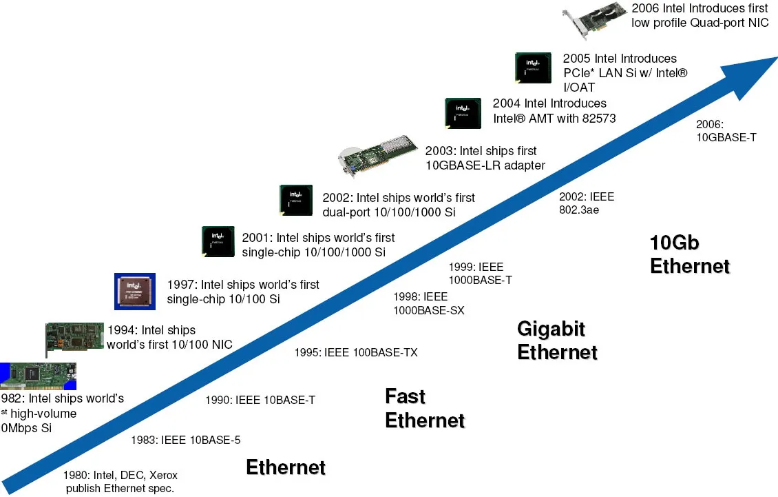
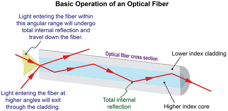
With the development of technology, in 2009, the IEEE released the 10Gbps Ethernet standard, namely IEEE 802.3ae, which supports a transmission rate of 10Gbps and is the mainstream Ethernet standard we currently use; 10Gbps Ethernet mainly uses optical fibers as the transmission medium.
1.1.3 OSI Open Systems Interconnection Model
Before explaining ETH Ethernet communication, we first need to understand the OSI Open Systems Interconnection model. The Open Systems Interconnection (OSI) model is a conceptual framework for network communication, which was developed by the International Organization for Standardization (ISO) in the 1980s. The OSI model divides the network communication process into seven layers, ranging from the Physical Layer (Layer 1) to the Application Layer (Layer 7). Each layer has its specific functions and responsibilities to ensure that information can be transmitted accurately and error-free between different computer systems.
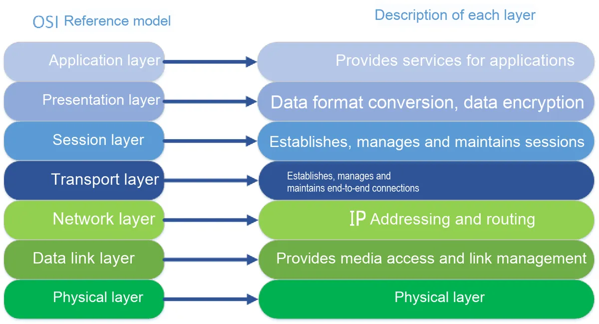
The OSI model is divided into seven layers, which are as follows from top to bottom:
- Application Layer:
- The application layer is the topmost layer of the OSI model, which directly provides services for users. Application layer protocols define the communication rules between application programs, such as HTTP, FTP, SMTP, DNS, etc.
- Presentation Layer:
- The presentation layer is responsible for data formatting and encryption. It defines data encoding methods, data compression, data encryption and decryption, etc.
- Session Layer:
- The session layer is responsible for establishing, managing and terminating sessions between applications. It provides functions such as session establishment, data exchange and session resumption.
- Transport Layer:
- The transport layer is responsible for end-to-end communication management, and provides functions including packet segmentation, reassembly, flow control and error detection. Common transport layer protocols include TCP (Transmission Control Protocol) and UDP (User Datagram Protocol).
- Network Layer:
- The network layer is responsible for the routing and forwarding of data packets, ensuring that data packets can traverse different networks to reach their destinations. It defines elements such as IP Address and routing protocols. Common network layer protocols include IP (IPv4 and IPv6), ICMP, IGMP, etc.
- Data Link Layer:
- The data link layer is responsible for establishing and managing data links between nodes, and it provides functions such as data frame encapsulation/decapsulation, error detection, and flow control.
- Physical Layer:
- The physical layer is responsible for transmitting bit streams, namely the electrical signals representing 0s and 1s, over physical media. It defines specifications such as electrical standards, interface protocols, and cable types. Common physical layer protocols and devices include Ethernet, USB, Bluetooth, and hubs.
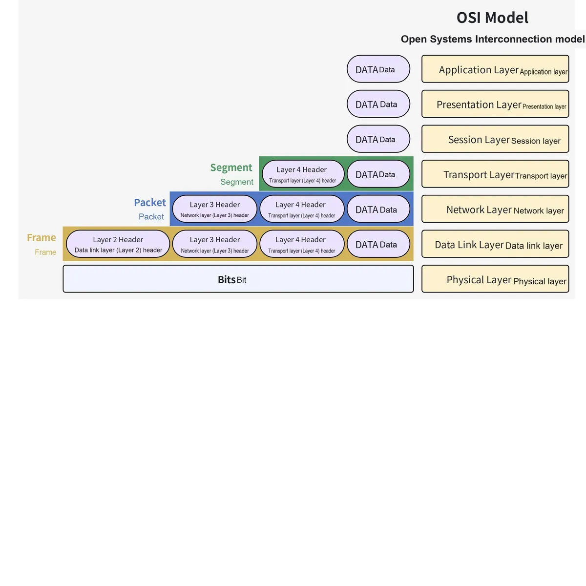
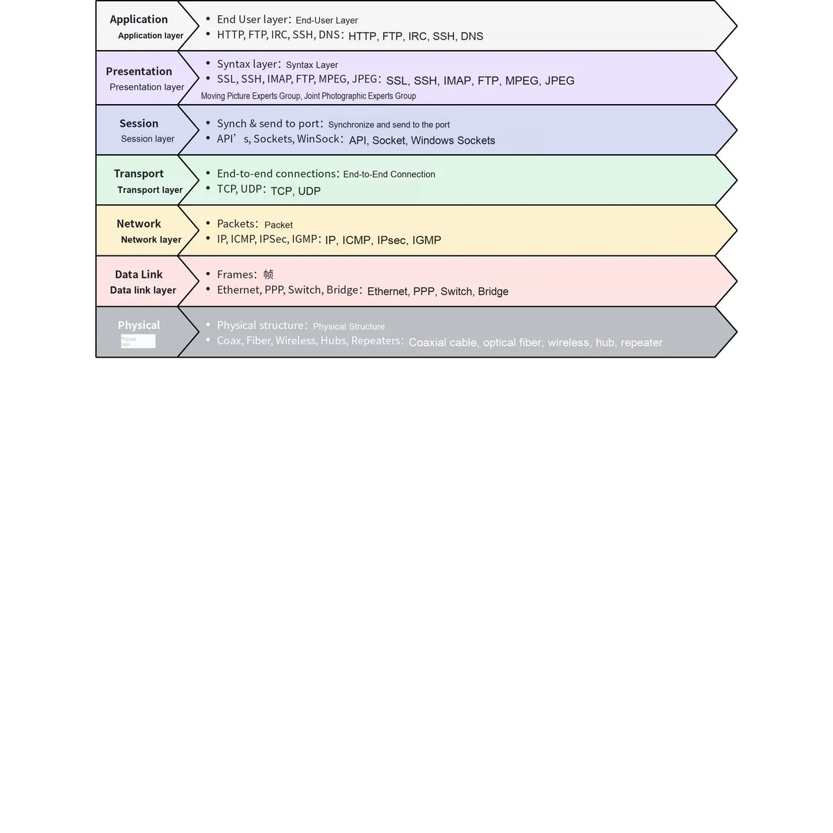
The relationship between Ethernet and the OSI model is as follows:
- Physical Layer: The physical layer of Ethernet corresponds to Layer 1 of the OSI model, and both are responsible for transmitting data bit streams over physical media. The physical layer of Ethernet covers transmission media such as optical fibers and twisted pairs, as well as relevant interface standards.
- Data Link Layer: The data link layer of Ethernet corresponds to Layer 2 of the OSI model, which is responsible for establishing and managing data links between nodes. The data link layer of Ethernet defines the frame format, error detection and correction mechanisms, etc.
- Network Layer: Although Ethernet itself does not have a well-defined network layer, Ethernet packets will pass through the network layer (such as the IP protocol) during transmission, which corresponds to Layer 3 of the OSI model.
Simply put, Ethernet is a specific implementation of the OSI model in a local area network environment, which provides specifications for the physical layer and the data link layer, while the OSI model offers a more general framework for understanding and designing various network Communication Protocols.
Engineers can use the OSI model to organize and model complex network system architectures. In this way, we can separate the operation layers of each system component according to their core functions. Through abstraction, the function of decomposing a system into smaller, more manageable parts makes it easier for people to conceptualize it as a whole. The OSI model does not specify the protocols used between layers, but rather the tasks that protocols perform. This model standardizes the development of network communications, enabling people to quickly understand, build, and decompose highly complex systems without prior knowledge of the systems.This type of model can also extract detailed information, so engineers do not need to understand every aspect of the model. In modern applications, we can abstract lower-level networks and protocols to simplify system design and development.
Common Network Communication Protocols
Network Communication Protocol is a set of rules and standards for data exchange in computer networks. It is the key to enabling communication between different hosts in a computer network, ensuring that data can be transmitted accurately and error-free across different hardware and operating systems. Network Communication Protocol defines rules covering various aspects including data format, transmission mode, error detection, routing, and data compression.
In network communication, common protocols include:
- TCP/IP Protocol: TCP (Transmission Control Protocol) is responsible for ensuring the correct transmission of data and provides a reliable, connection-oriented service; IP (Internet Protocol) is responsible for sending data packets from the source address to the destination address and provides a connectionless service
- HTTP Protocol: HTTP (Hypertext Transfer Protocol) is a protocol used for transmitting hypertext (HTML) over the World Wide Web, primarily for web browsing.
- FTP Protocol: FTP (File Transfer Protocol) is used for uploading and downloading files over a network
- SMTP Protocol: SMTP (Simple Mail Transfer Protocol) is used for sending emails
- POP3 Protocol: POP3 (Post Office Protocol Version 3) is used to receive emails
- IMAP protocol: IMAP (Internet Mail Access Protocol) is used to receive and manage emails
- DNS Protocol: The DNS (Domain Name System) protocol is used to convert human-readable domain names into machine-recognizable IP Address
- DHCP Protocol: DHCP (Dynamic Host Configuration Protocol) is used to automatically assign IP Address and other network configuration information to devices on the network
- SNMP Protocol: SNMP (Simple Network Management Protocol) is used to collect information from network devices and manage them.
- SSL/TLS Protocol: SSL (Secure Sockets Layer) and TLS (Transport Layer Security) are protocols used to provide encrypted communication over networks.
1.1.3.1 Prerequisite Knowledge for Understanding the OSI Model
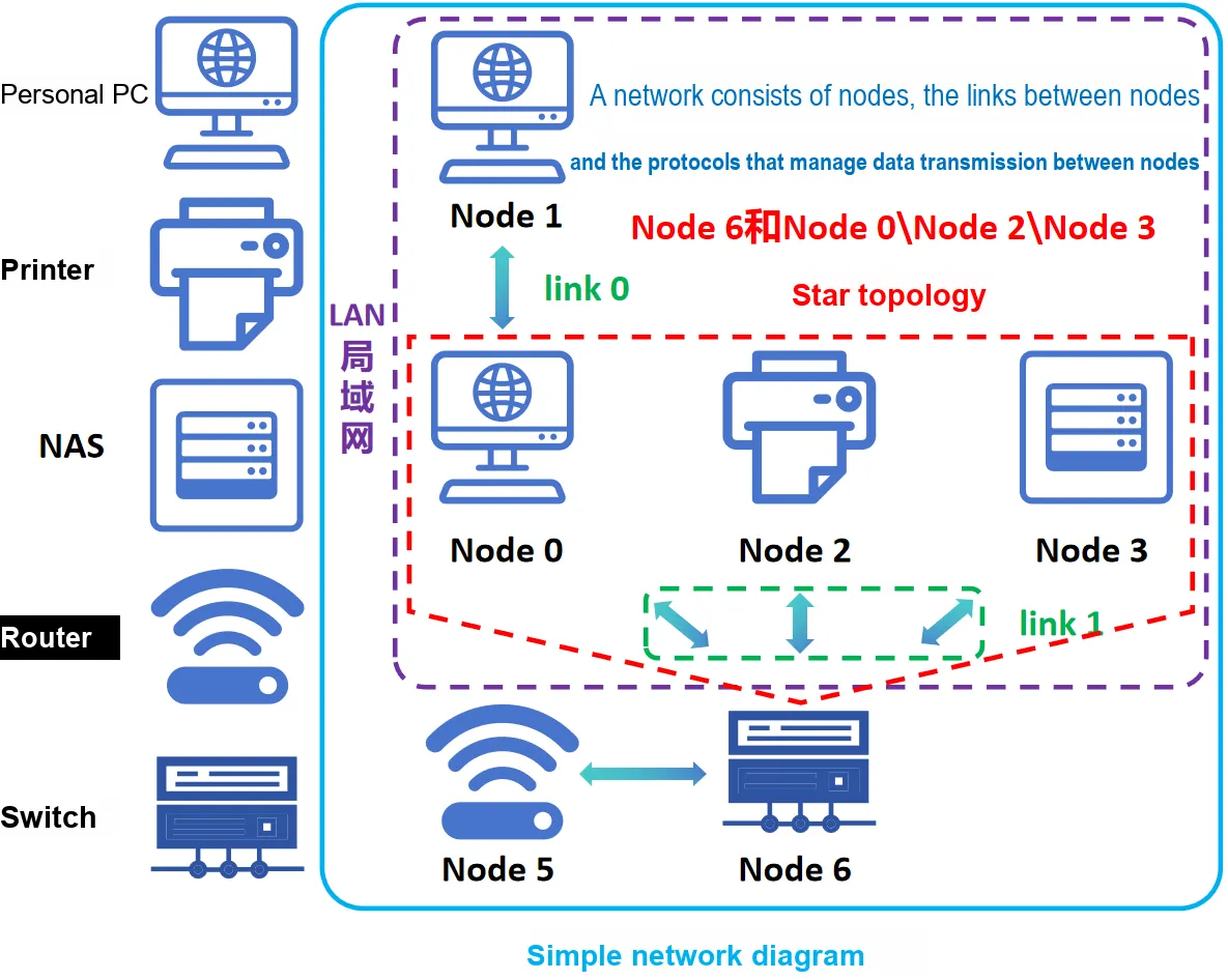
Before understanding the OSI model, we need to know the following common terms in network communication, including node, link, protocol, network and topology.
1. Node
In computer networks, a node refers to any device that connects to a network and is capable of data communication, such as a computer, router, switch, etc.
A node is a fundamental component unit in a network, which is used to transmit, receive and forward data.
Nodes can be adjacent to each other, among which node 0 can be directly connected to node 1.
Intermediate nodes can also exist between nodes; for example, a switch or a router can be placed between node 0 and node 2.
2. Link
A link refers to a physical line or logical path connecting various nodes in a network, which can be an actual communication line or a virtual communication path.
A link can be wired (e. g., Ethernet cable) or wireless (e. g., Wi-Fi).
A link can be point-to-point or point-to-multipoint (link 0 is point-to-point, while link 1 is point-to-multipoint).
3. Protocol
"Protocols define the rules governing the syntax (what can be communicated), semantics (how communication proceeds), and synchronization (when communication occurs and at what speed) in the communication management process. A protocol can be implemented by hardware, software, or a combination of both. Protocols can be created by anyone, but the most widely adopted ones are all based on standards. "
—— Walter Goralski, *Illustrated Network: How TCP/IP Works in Modern Networks*
Simply put, a protocol refers to the rules and standards for communication in a network, which specifies mechanisms such as the format, sequence, and error handling of data transmission.
4. Network
A network is a complex system composed of multiple nodes and links, which enables data exchange and communication between nodes. Common types of networks include: LAN, HAN, CAN, MAN, WAN, BAN or VPN:
- Local Area Network (LAN): It covers a relatively small area, usually within a single building or a campus, featuring high transmission speed and low cost.
- Wide Area Network (WAN): It features a wide coverage that can span across countries or even the globe, yet comes with relatively low transmission speed and high cost.
- Metropolitan Area Network (MAN): A network type that falls between a Local Area Network and a Wide Area Network, typically covering a city and its surrounding areas.
- Personal Area Network (PAN): a user-centric network that relies on wireless communication technologies such as Bluetooth and ZigBee
- Broadcast Network (BAN): A point-to-multipoint communication network that enables broadcast transmission of information
- Virtual Private Network (VPN): A private network established over a public network (such as the Internet) that provides a secure communication path
- Controller Area Network (CAN): a network standard specifically designed for communication between electronic systems inside automobiles
- Industrial Control System Network (MAN): A network used for communication in industrial automation and control systems
5. Topology
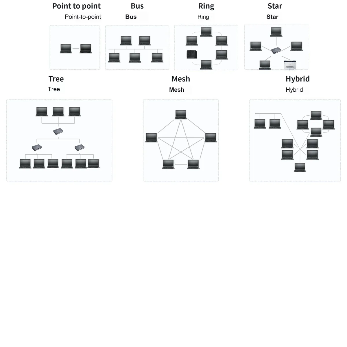
Topology refers to the physical or logical layout of nodes and links in a network, which affects the performance and reliability of the network. Common topologies include star, ring, bus, tree, and mesh, among others.
1.1.3.2 OSI Physical Layer
1. Basic Functions of the Physical Layer
The physical layer of the OSI model is the first layer of the seven-layer OSI model, which defines the physical and electrical characteristics of network communication. The following are some key elements of the physical layer:
- Nodes (devices) and network hardware: Nodes in a network refer to devices capable of transmitting, receiving or relaying data. Common network devices include
- Hub: A basic network device used to connect multiple Ethernet devices to logically form a single network segment.
- Repeater: A device used to extend network coverage by retransmitting or amplifying signals to reduce signal attenuation.
- Router: A device used to connect different network segments and select the optimal path to forward data packets
- Computers, printers: terminal devices used for transmitting, receiving and processing data
- hardware components: such as antennas (for wireless communication), amplifiers (for signal enhancement), network interface cards (NIC, Network Interface Card, providing network interfaces)
- Device Interface Mechanism: The device interface mechanism involves physical connection methods and interface standards
- Cable Connection: The cable is connected to the port on the device via a connector (e. g. RJ45), such as an Ethernet port.
- Connector Specifications: For example, an RJ45 connector typically has 8 pins, and each pin has a specific function (transmitting, receiving, etc.)
- Pin Status: The active state of a pin is determined by an electrical signal, which is typically a high level or a low level.
- Functions and Program Logic: The functions of each connector pin and the communication logic between network devices
- Pin Functions: For example, in Ethernet, some pins are used for transmitting data (TX) and others for receiving data (RX).
- Program Logic: The logic that governs the sequence of events, ensuring that nodes can communicate properly at the second layer (the data link layer)
- Cable Protocols and Specifications: Network Communication Protocol and specifications define the technical details of network communication
- Ethernet (CAT): Defines the standards for Ethernet cables and connectors
- USB: a standard for connecting computers and peripheral devices
- Digital Subscriber Line (DSL): a technology that transmits digital data over telephone lines
- Cable Type: Different types of cables are suitable for different network environments
- Shielded Twisted Pair (STP): used to reduce electromagnetic interference
- Unshielded Twisted Pair (UTP): commonly used for Ethernet connections
- Coaxial cable: used for TV and broadband internet connections
- Signal Type: The transmission mode of network signals
- Baseband signal: transmits one data bit stream at a time, and is commonly used in Ethernet
- Broadband signal: A type of signal that transmits multiple data bit streams simultaneously, which is commonly used for broadband Internet access.
- Signal transmission method: Signal transmission can be wired or wireless.
- Wired transmission: such as Ethernet (electrical signals) and optical fibers (optical signals)
- Wireless transmission: e. g., WiFi (radio waves), with consideration given to the frequency (such as 2.4 GHz or 5 GHz)
- Network Standard: such as 100BASE-T, which defines the transmission rate and medium type of Ethernet
2. Basic Data Units: Bit and Byte
For communication at the physical layer, we need to understand concepts such as data bits and bytes, data bit transmission and synchronization, and transmission modes: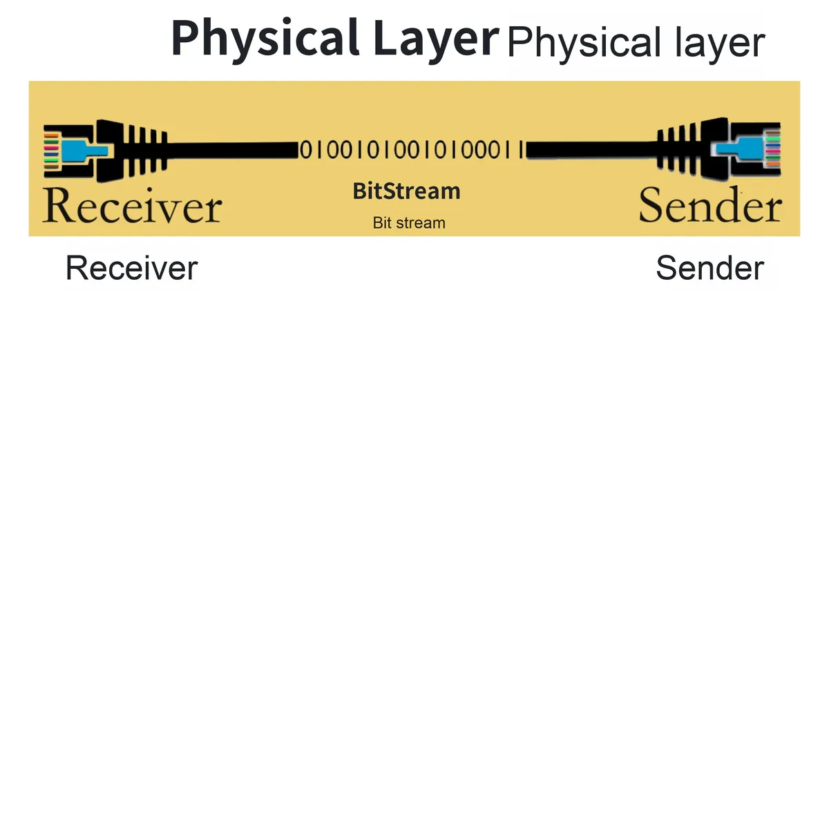
- Data units at the physical layer: data bits and bytes
- Data bit (bit):
- The smallest data transmission unit, which has only two states: 0 and 1
- All higher-level data units (such as bytes, frames, packets, etc.) are composed of data bits.
- Byte:
- Consists of 8 data bits and is a basic data unit commonly used in computer processing
- A byte can represent 256 distinct values (2^8)
- Data bit (bit):
- Data Bit Transmission and Synchronization
- Data Rate (Transmission Rate):
- It is measured by the number of data bits transmitted per second, usually in bps (bits per second), such as Mbps (megabits per second) and Gbps (gigabits per second).
- Data bit synchronization:
- The transmitting end and the receiving end must be coordinated at the same time reference point to ensure that data bits can be transmitted and received correctly.
- Synchronous mode can be implemented by means of clock signals or synchronization information embedded in the data stream.
- Data Rate (Transmission Rate):
- Transmission Mode
- Signal transmission method:
- Wired transmission: e. g., electrical signals (Ethernet), optical signals (optical fiber)
- Wireless transmission: e. g. radio waves (WiFi, Bluetooth)
- Modulation Technology:
- In wireless communication, signal transmission is realized by means of modulation technologies, such as AM, FM, QAM and so on.
- Signal transmission method:
- Transmission Mode
- Simplex Mode:
- Data can only be transmitted in one direction, meaning that one node can only send data while the other can only receive it.
- For example, radio and television signals
- Half-Duplex Mode:
- Data can be transmitted in both directions, but not simultaneously, meaning that transmission and reception have to be performed alternately.
- For example, walkie-talkie communication
- Full-duplex mode (Full-Duplex):
- Data can be transmitted in both directions simultaneously, meaning sending and receiving can take place at the same time.
- For example, modern telephone communication, full-duplex Ethernet
- Simplex Mode:
1.1.3.3 OSI Data Link Layer
1. Basic Functions of the Data Link Layer
The second layer of the OSI model is the data link layer, which is responsible for providing reliable data transmission between directly connected network nodes. The data link layer organizes the bit streams transmitted by the physical layer into data frames, and handles error detection and correction to ensure data reliability. The main functions of the data link layer include:
- Data Encapsulation:
- Encapsulate the packets of the network layer into frames, and add control information (such as addresses and error detection codes) to the header and trailer of the frames;
- Each frame consists of a frame header, a data field and a frame trailer;
- Physical Address Addressing:
- Use MAC addresses (Media Access Control addresses) to uniquely identify each device in the network;
- Frame transmission and reception are performed based on MAC addresses;
- Frame Synchronization:
- Ensure that the start and end of a frame can be correctly identified, which is usually achieved through specific frame start and end flags;
- Error Detection and Correction:
- Use Cyclic Redundancy Check (CRC) or other error detection codes to detect errors in transmission;
- After error detection, retransmission can be requested to correct the erroneous data.
- Flow Control :
- Adjust the data transmission rate between the sender and the receiver to prevent the receiver buffer from overflowing
- Link Management:
- Establish, maintain and release physical links
- including the link initialization, link maintenance and link release processes
2. LLC Layer and MAC Layer
The data link layer is usually divided into two sublayers: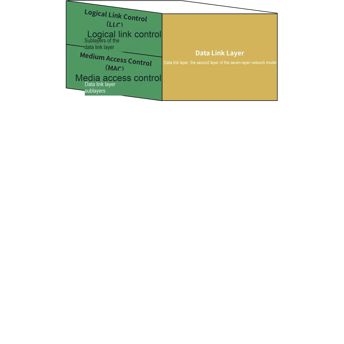
- Logical Link Control Sublayer (LLC, Logical Link Control):
- Responsible for interfacing with the network layer and handling multiple network protocols
- Provides flow control, error control and frame synchronization functions
- Media Access Control sublayer (MAC, Media Access Control):
- Responsible for the interface with the physical layer and controlling access to the shared medium
- Implement physical address addressing, frame delimitation and medium access control
- The MAC sublayer is responsible for assigning hardware identification numbers, namely MAC addresses, to uniquely identify each device on the network.
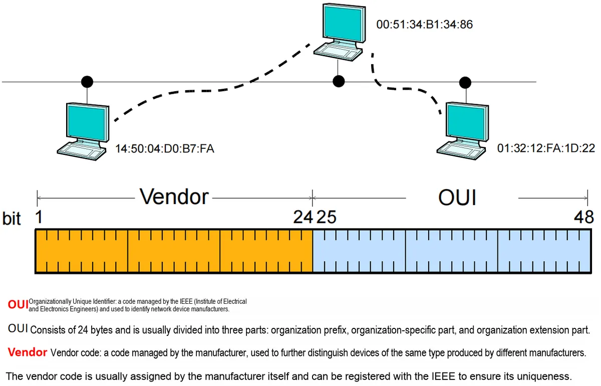
- A MAC address consists of an OUI (Organizationally Unique Identifier) and a Vendor code
MAC address
A MAC address (Media Access Control address) is typically used to uniquely identify the network interface of a network device. The standard format of a MAC address consists of six groups of two hexadecimal digits, separated by either colons (:) or hyphens (-). Listed below are some common examples of MAC address representations:
- Separated by colons:
00:1A:2B:3C:4D:5EAA:BB:CC:DD:EE:FF
- Separated by hyphens:
00-1A-2B-3C-4D-5EAA-BB-CC-DD-EE-FF
- no delimiter:
001A2B3C4D5EAABBCCDDEEFF
Each MAC address consists of 48 bits (6 bytes), where the first 24 bits (the first 3 bytes) correspond to the Organizationally Unique Identifier (OUI) assigned by the manufacturer, and the last 24 bits represent the unique serial number assigned by the manufacturer to the device.
The first digit of a MAC address must be an even number, meaning that the first digit of the MAC address must be 0; an odd first digit indicates a broadcast address. The second digit must be an even number — if it is odd, the address is a unicast address, which can only be used as a destination address and not as a source address.
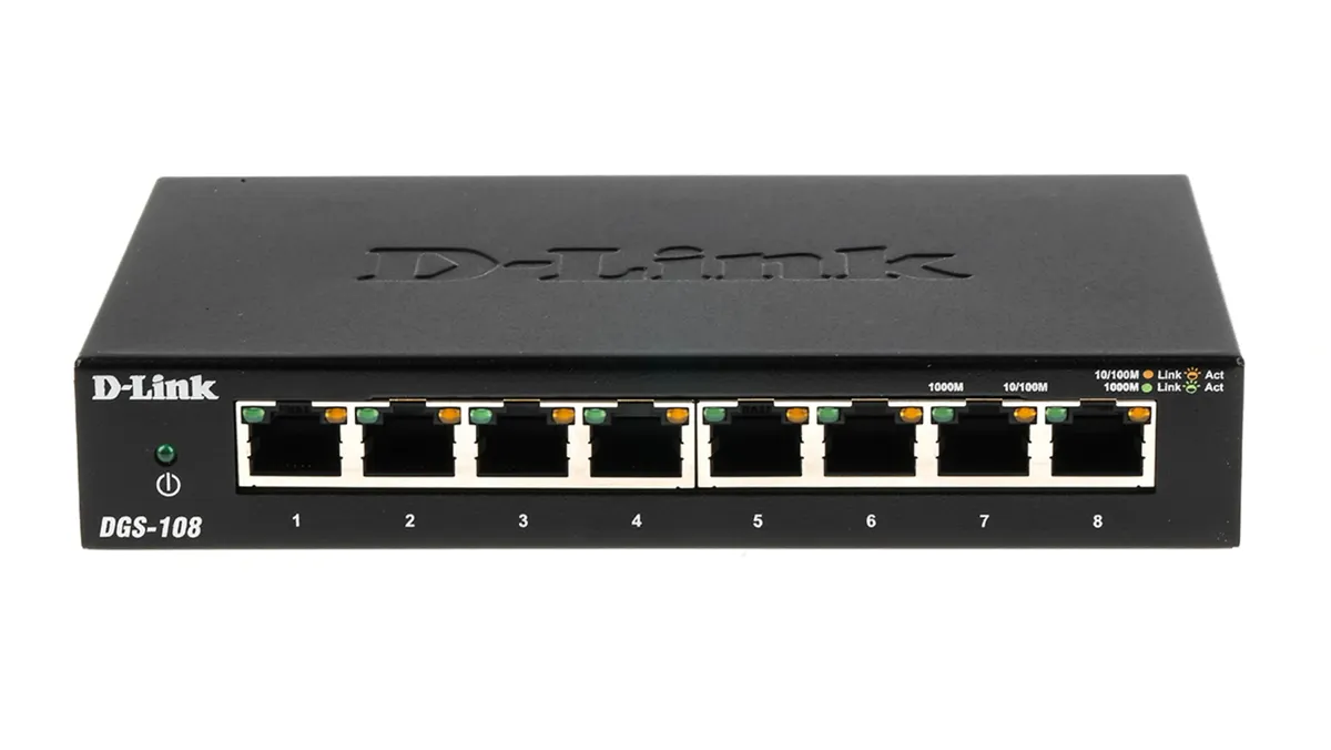
A switch operates at the data link layer (Layer 2) and keeps track of the MAC addresses of all devices on a network by maintaining a MAC address table, also known as a Content Addressable Memory table or CAM table. Whenever the switch receives a data frame, it records the source MAC address and the receiving port to update the MAC address table, then forwards the data frame to the appropriate port based on the destination MAC address, enabling efficient communication within a local area network.
1.1.3.4 OSI Network Layer
1. Basic Functions of the Network Layer
The network layer of the OSI model is the third layer, which is responsible for packet forwarding and routing to ensure that data reaches the destination node from the source node. Through the network layer, we can not only realize node-to-node communication, but also transmit data between different local area networks (LANs) via routers. The network layer mainly addresses issues such as network topology, path selection and network connection.
The main functions of the network layer include:
- Path Selection and Routing:
- Determine the optimal path for data packets from the source node to the destination node.
- Dynamic routing tables are determined and maintained by using routing protocols and algorithms such as OSPF and BGP.
- Logical Address Allocation:
- Use an IP Address (IPv4 or IPv6) to identify each device in the network.
- An IP Address consists of a network part and a host part, which is used to identify the location of a device in the network.
- Packet Encapsulation and Decapsulation:
- Encapsulate the data segments from the transport layer into data packets and add network layer header information.
- The receiver decapsulates the data packet, extracts the data segment and delivers it to the transport layer.
- Grouping and Regrouping:
- Split large data packets into smaller fragments according to the network MTU (Maximum Transmission Unit).
- The receiver reassembles the packets to restore the original data packets.
- Error Handling and Diagnostics:
- Detect and handle errors that may occur during packet transmission.
- It uses protocols such as ICMP (Internet Control Message Protocol) to report network errors and diagnostic information.
2. Routers and Routing Tables
The role of a router at the network layer is to forward data packets from the source node to the destination node, connect different networks and manage the communication between them, connect to Internet Service Providers (ISPs) to provide Internet access, and perform Network Address Translation (NAT) and security functions, so as to ensure the efficient and reliable transmission of data across multiple networks.
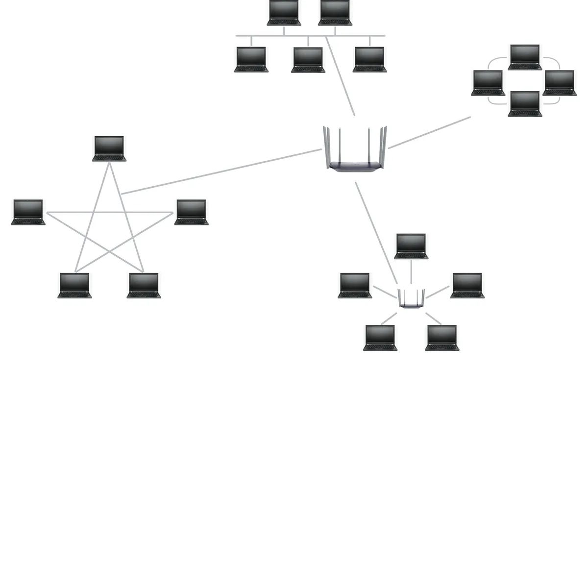
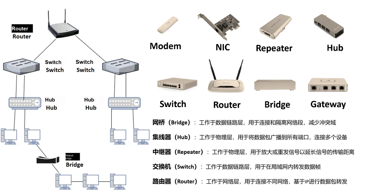
Routers store all address and routing information in a routing table, which contains network layer information and is used to determine the forwarding path of data packets. Below is a simple example of a routing table, showing the common fields and contents of a routing table:
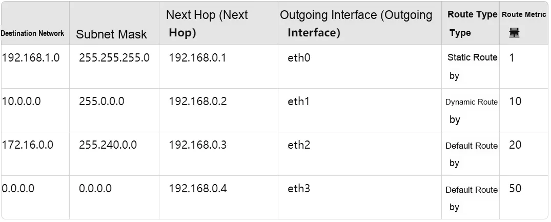
The router includes the following information:
- Destination Network: The network address of the packet's destination
- Subnet Mask: Used to determine the range of the destination network, it defines the network part and the host part of an IP Address
- Next Hop: the IP Address of the next router or gateway to the destination network
- Outgoing Interface: The network interface used to send data packets to the destination network
- Route Type: Indicates the source type of a route, such as static route, dynamic route, default route, etc.
- Routing Metric: A value used to measure path priority; the smaller the value, the higher the priority
The meaning of the above example is as follows:
- 192.168.1.0/24 network traffic is sent via the next-hop router at 192.168.0.1 through the eth0 interface. This route is statically configured with a metric of 1
- 10.0.0.0/8 network traffic is sent via the next-hop router at 192.168.0.2 through the eth1 interface. This route is dynamically learned with a metric of 10
- 172.16.0.0/12 network traffic is sent via the next-hop router at 192.168.0.3 through the eth2 interface. This is a default route configuration with a metric of 20.
- 0.0.0.0/0 indicates a default route, which matches all unspecified destination networks; traffic is forwarded via the next-hop router at 192.168.0.4 and sent out through the eth3 interface. With a metric of 50, this is typically the least preferred route.
Once a node is connected to the Internet, it will be assigned an Internet Protocol (IP) address. There are currently two common types of IP Address in use:
- IPv4 (Internet Protocol version 4):
- A widely used version of the IP protocol that employs a 32-bit address space
- Supports grouping, routing, and inter-network interconnection
- An IPv4 address consists of four decimal numbers, each ranging from 0 to 255, separated by dots (.)
- Example: 172.16.254.4
- IPv6 (Internet Protocol version 6):
- The next-generation IP protocol, which adopts a 128-bit address space, addresses the issue of IPv4 address exhaustion.
- offers better scalability, auto-configuration and security
- An IPv6 address is 128 bits long and consists of 8 groups of hexadecimal numbers, each separated by a colon (:)
- Example: 2001:0db8:85a3:0000:0000:8a2e: 0370:7334
Unreachable IP
An unreachable IP refers to a specific IP Address that cannot be connected to via the network. The common causes of IP unreachability are as follows:
- Network Topology Issue:
- The network segment where the target IP resides is not in the same subnet as the current network, so it cannot be reached via direct routing.
- There is a problem with the configuration of network devices (such as routers and switches), which results in the failure to forward traffic to the target IP address.
- Firewall Block:
- The firewall rules have blocked access to the target IP address.
- Security groups or access control lists (ACLs) restrict connections to the target IP address
- Target host failure:
- The network card or network interface of the target host malfunctions and fails to provide external services.
- The target host has been shut down or the network connection has been disconnected
- Routing Problem:
- There is an issue with the routing table configuration, and no suitable path to the destination IP can be found.
- Incorrect gateway settings result in the failure to forward data packets properly.
When attempting to access an unreachable IP, you will usually receive error prompts such as "Network unreachable" or "Host unreachable". When a data packet fails to reach the target IP Address, the network device or router will return an ICMP (Internet Control Message Protocol) unreachable message to inform the sender that the target IP Address is unreachable.
ICMP messages typically contain the following important fields:
- Type and Code: Identify the type of the ICMP packet and the specific reason
- Checksum: Used to detect whether an ICMP packet is corrupted
- Other fields: Depending on the packet type, these may include additional information such as source IP, destination IP, timeout period, etc.
ARP (Address Resolution Protocol) is used to map IP addresses at the network layer to MAC addresses at the data link layer. This process is critical for communication between devices within a Local Area Network (LAN), since MAC addresses are required for packet transmission at the link layer, and ARP acts as a bridge between the network layer and the data link layer.
Domain Name and IP Address
A domain name is a string corresponding to an IP Address that is easier to remember and is used to access resources on the Internet. A domain name is resolved into an IP Address via the Domain Name System (DNS), and the structure of a domain name is as follows:
- Top-Level Domain (TLD): the last segment of a domain name, such as
. com,. org,. net - Second-level domain: the part immediately preceding the top-level domain, such as
example.comtheexample - Subdomain: A portion of a domain name that is further divided, for example
blog.example.comtheblog
DNS (Domain Name System) is a system that resolves domain names into IP Addresses, allowing users to access Internet resources using easy-to-remember domain names. The DNS resolution process is as follows:
- User enters domain name: The user enters a domain name in the browser
- DNS query: The browser initiates a query to the DNS server, requesting to resolve the domain name into an IP Address
- DNS Server Response: The DNS server returns the IP Address corresponding to the domain name
- Access Resources: The browser uses the returned IP Address to establish a connection with the target server and access the resources
For example, when a user enters www.example.com , the DNS will resolve it to an IP Address such as 93.184.216.34, and the browser will then use this IP Address to access example.com resources on the server.
Simply put, domain names and IP Address are two important identification methods on the Internet. They are mapped to each other through DNS (Domain Name System), allowing users to access network resources via easy-to-remember domain names instead of hard-to-remember IP Address.
3. Typical Gateway and Subnet Mask Configuration
When configuring network devices such as computers, routers or embedded systems, it is usually necessary to set the IP Address, subnet mask and gateway address. For example:
- IP Address: 192.168.1.100
- Subnet Mask: 255.255.255.0
- Gateway Address: 192.168.1.1
A gateway address is the address required by devices on a network to communicate with other networks via a router or other gateway device. It usually points to the router address of the subnet where the device is located, so that when the device needs to access an external network, it will send data packets to the gateway, which is responsible for forwarding the data packets to the destination.
For example, there are Network A and Network B: the IP Address range of Network A is "192.168.1.1~192.168.1.254" with a subnet mask of 255.255.255.0; the IP Address range of Network B is "192.168.2.1~192.168.2.254" with a subnet mask of 255.255.255.0.In the absence of a router, TCP/IP communication cannot be carried out between two networks. Even if the two networks are connected to the same switch (or hub), the TCP/IP protocol will, based on the different results of the "AND" operation between the subnet mask (255.255.255.0) and the host's IP address, determine that the hosts in the two networks are located in different networks. To realize communication between these two networks, a gateway must be used.If a host in Network A finds that the destination host of a data packet is not in the local network, it will forward the data packet to its own gateway, which then forwards the packet to the gateway of Network B, and the gateway of Network B further forwards the packet to a specific host in Network B. This is the process of Network A forwarding data packets to Network B.
A subnet mask is used to divide an IP Address into two parts: a network address and a host address, so as to determine the subnet range where a device is located. It defines which parts of the IP Address belong to the network segment and which belong to the host segment. A subnet mask cannot exist independently and must be used in combination with an IP Address. With the subnet mask, a device can determine whether the target IP Address is within the same subnet, thereby deciding whether to forward data packets via a gateway.
Common subnet mask formats are as follows:
- 255.255.255.0: Typically used to divide a Class C network into 256 host addresses, 254 of which are available (the remaining two are reserved for network and broadcast addresses)
- 255.255.0.0: Used to divide a Class B network into 65536 host addresses
- 255.0.0.0: Used to divide a Class A network into 16777216 host addresses
As can be seen, the network address part corresponding to an IP Address is represented by 1, while the host address part corresponding to an IP Address is represented by 0; the network address can be obtained by performing a logical AND operation on the IP Address and the subnet mask:
- 0 ANDed with any number equals 0
- The bitwise AND of 1 and any number equals the number itself.
4. Basic Data Unit: Data Packet
At the network layer, the data unit is called a packet. A packet consists of a network layer header and a data payload.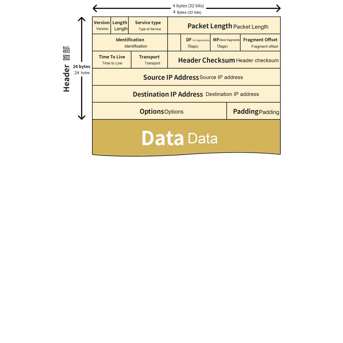
- Header:
- Source IP Address: The IP Address of the sending node
- Destination IP Address: The IP Address of the receiving node
- Other control information: such as protocol type, time-to-live (TTL), identifier, flags, and fragment offset
- Data Frame / Data Payload:
- Contains the data segments received from the transport layer
Taking IPv4 packets as an example, let's explain the basic structure of data packets:
Header:
- Version: 4
- IHL: 5 (20 bytes)
- Type of Service: 0
- Total Length: 60 bytes (header 20 bytes + data 40 bytes)
- Identification: 12345
- Flags: 0x2 (Don't Fragment)
- Fragment Offset: 0
- TTL: 64
- Protocol: 6 (TCP)
- Header Checksum: 0x1a2b
- Source IP Address: 192.168.1.10
- Destination IP Address: 192.168.1.20
- Options: None

Payload (Data):
- Data: [TCP Segment]
  - Source Port: 12345
  - Destination Port: 80
  - Sequence Number: 123456789
  - Acknowledgment Number: 987654321
  - Data Offset: 5 (20 bytes)
  - Flags: 0x18 (PSH, ACK)
  - Window Size: 65535
  - Checksum: 0xabcdef
  - Urgent Pointer: 0
- Data: "Hello, World!"- Header
- Version: 4 bits, indicating the version of the IP protocol; the value for IPv4 is 4
- Internet Header Length (IHL): 4 bits, indicating the length of the IP header in units of 32-bit words (4 bytes)
- Type of Service (ToS): an 8-bit field that specifies the priority and quality of service requirements of the data packet.
- Total Length: A 16-bit field that indicates the total length of the entire data packet (including both the header and the payload), measured in bytes.
- Identification: 16 bits, used to identify the uniqueness of a data packet, and is typically used during sharding
- Flags: 3 bits, indicating whether the packet is sharded and whether there are more shards
- Fragment Offset: A 13-bit field that indicates the position of a data packet in sharding
- Time to Live (TTL): an 8-bit field that limits the lifespan of data packets in the network to prevent infinite loops
- Protocol: 8 bits, indicating the type of upper-layer protocol carried in the data packet, such as TCP and UDP
- Header Checksum: 16 bits, used to detect errors in the header
- Source IP Address (Source IP Address): 32 bits, the IP Address of the device that sends the data packet
- Destination IP Address: A 32-bit value representing the IP Address of the device that receives the data packet
- Options: An optional field used to provide additional control information (e. g., timestamps, record routing, etc.)
- Padding: Used to ensure that the header length is a multiple of 32 bits
- Data Payload
- Data Segment (Data): Contains the protocol data unit from the transport layer, such as a TCP segment or a UDP datagram
1.1.3.5 OSI Transport Layer
1. Basic Functions of the Transport Layer
The transport layer is the fourth layer in the OSI model, whose main function is to provide reliable end-to-end data transmission services between the source and the destination. The primary focus of the transport layer is to ensure that data packets arrive in the correct order without loss or errors, or can be seamlessly recovered when necessary. Data segmentation, transmission control, flow control and error control are typically the key concerns of the transport layer.
The main functions of the transport layer can be summarized as follows:
- Data Segmentation and Reassembly: The transport layer splits the data from the session layer into smaller segments, then reassembles these segments at the receiving end to restore the original data
- Transmission Control: Provides end-to-end communication control to ensure the reliability and accuracy of data transmission from the source node to the destination node
- Error Detection and Correction: Use mechanisms such as checksums to detect errors that may occur during transmission and provide corresponding correction measures
- Flow Control: manages the data transmission rate to prevent the sender from sending data too fast for the receiver to process
- Port Management: Use Port Numbers to identify different applications, so as to enable multiple network communications simultaneously on the same device
2. TCP and UDP Protocols
Common transport layer protocols can be divided into two categories: TCP (Transmission Control Protocol) and UDP (User Datagram Protocol):
- TCP (Transmission Control Protocol)
- Connection-oriented: A connection needs to be established before data transmission, and a reliable connection is established through the Three-Way Handshake
- Reliability: Provides reliable data transmission services, and ensures data integrity and sequence through acknowledgment (ACK) and retransmission mechanisms
- Flow Control: Flow control is implemented through the sliding window mechanism to ensure that the sender will not overwhelm the receiver.
- Error Detection and Correction: Use checksums to detect errors in data transmission and perform necessary retransmissions
- Typical Applications: Protocols requiring reliable transmission such as HTTP/HTTPS, FTP, SMTP, etc.
- UDP (User Datagram Protocol)
- Connectionless: No connection establishment is required, data packets are transmitted independently, which features relatively high speed but does not guarantee reliability
- Simple and efficient: It has no acknowledgment and retransmission mechanism, making it suitable for applications with high real-time requirements
- Typical Applications: Applications that do not require strict reliability, such as DNS queries, video streaming, and online games
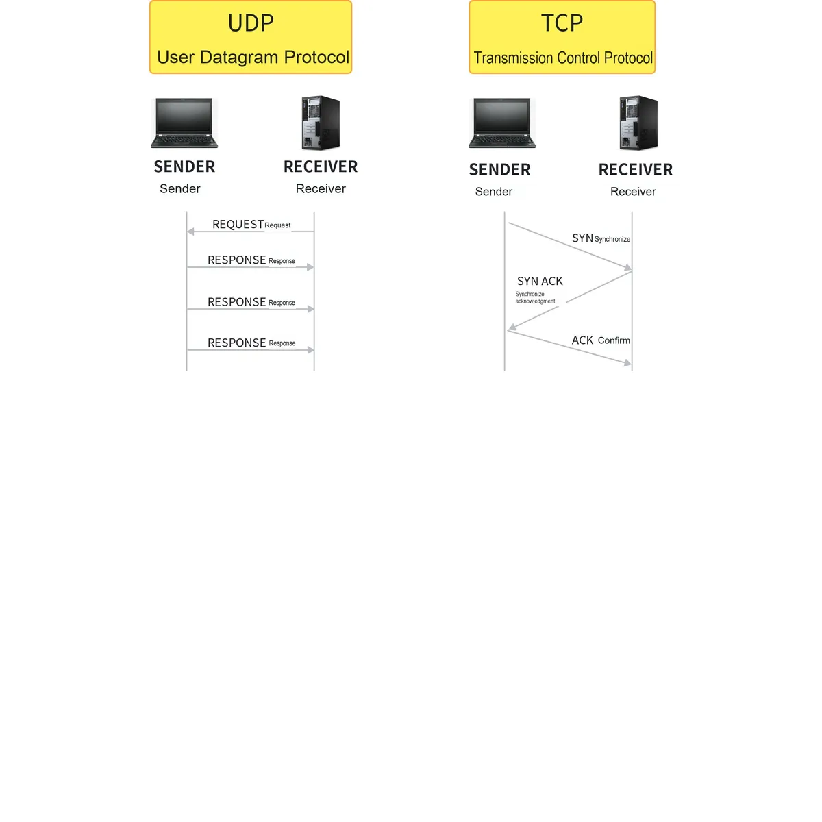
Simply put, TCP is a connection-oriented protocol that ensures correct data reception through mechanisms such as handshake confirmation and retransmission. It prioritizes the integrity and accuracy of data, sacrificing some transmission speed in exchange for the reliability and orderliness of data transmission. TCP is ideally suited for application scenarios that require stable and error-free transmission, such as web browsing and file transfer.UDP is a connectionless protocol that does not require complex reliability mechanisms such as acknowledgment and retransmission, nor does it need to establish or maintain connection states in advance. UDP does not guarantee that data packets will successfully reach the destination, nor can it ensure that data packets will not be lost or arrive out of order. UDP prioritizes speed at the cost of certain reliability and orderliness. It is suitable for application scenarios that have high requirements for real-time performance but relatively low requirements for data integrity, such as video conferencing and online games.
Socket
When TCP and UDP transmit data, it is necessary to specify the IP address and Port Number of the target device. The combination of this IP address and Port Number is called a "Socket". For example, 192.168.1.100:80 represents a socket with the IP address 192.168.1.100 and the Port Number 80.
Socket is a very important concept in network communication, which defines the following key elements:
- IP address
- Used to identify the location of devices in the network
- Determine which device the data packet should be sent to
- Port Number
- Used to identify a specific application running on the device
- Distinguish between different network applications on the same device
- Common Port Numbers have predefined purposes: for example, 80 is used for HTTP, 22 for SSH, and so on.
- Protocol Type
- typically TCP or UDP
- determines characteristics such as the reliability and orderliness of data transmission
Socket (socket) is a fundamental tool for network communication, which provides a mechanism for applications on different devices to exchange data over the network. Socket is an abstract interface between the application layer and the transport layer, which encapsulates the complexity of underlying network protocols (such as TCP/IP or UDP) and provides developers with a simple way to send and receive data. Network applications use sockets to communicate with remote devices. A socket can be a "Client socket" that actively initiates a connection, or a "server socket" that passively listens for connection requests.
3. Basic Data Unit: Data Segment
The data unit of the transport layer is called a segment. In TCP, it is referred to as a TCP segment; in UDP, it is called a UDP datagram.
The structure of a typical TCP segment is as follows:
+------------------------------------------------------------+
| Source Port: 12345 (16 bits)        | Destination Port: 80 (16 bits)|
+------------------------------------------------------------+
| Sequence Number: 1000 (32 bits)                            |
+------------------------------------------------------------+
| Acknowledgment Number: 2000 (32 bits)                      |
+-------------------+-------+-----------+--------------------+
| Data Offset: 5 (4 bits)| Reserved (6 bits) | Control Flags: 0x18 (PSH, ACK) |
+-------------------+-------+-----------+--------------------+
| Window Size: 4096 (16 bits)                                 |
+------------------------------------------------------------+
| Checksum (16 bits)                  | Urgent Pointer: 0 (16 bits) |
+------------------------------------------------------------+
| Options: (optional, 0 bits)                                |
+------------------------------------------------------------+
| Data: "Hello, TCP!" (10 bytes)                             |
+------------------------------------------------------------+
Here, it is assumed that the source port is 12345, the destination port is 80 (HTTP), the sequence number is 1000, the acknowledgment number is 2000, the window size is 4096, and the segment carries the data "Hello, TCP!"; among the control flags, 0x18 indicates that both the PSH and ACK flags are set; the checksum is calculated by the sender to ensure data integrity.
Wherein:
- Source Port: the Port Number of the data sender
- Destination Port: the Port Number of the data receiver
- Sequence Number: The serial number of the data segment, which ensures the order of data packets
- Acknowledgment Number: The sequence number confirming that the data has been received
- Data Offset: The length of the TCP header, in units of 32-bit words (4 bytes)
- Reserved: Reserved bit, usually set to 0
- Control Flags: including URG, ACK, PSH, RST, SYN, FIN, etc.
- Window Size: Used for flow control, indicating the amount of data that can be received
- Checksum: Used for error detection
- Urgent Pointer: If the URG flag is set, it indicates the location of urgent data
- Options: An optional field used to specify special control information
- Data: the actual data payload being transmitted
Ports and Unreachable Ports
A port is a concept in computer networks used to identify a specific application or process on a computer. Specifically, a port is a 16-bit integer with a value ranging from 0 to 65535. Every network application running on a computer is bound to a unique Port Number to receive data packets from the network. When an application receives data over the network, it determines which program should process the data based on the destination Port Number. This enables multiple applications to run simultaneously on the same computer.
Common Port Numbers include:
- Ports 20 and 21: Used for FTP (File Transfer Protocol)
- Port 22: Used for SSH (Secure Shell Protocol)
- Port 80: Used for HTTP (Hypertext Transfer Protocol)
- Port 443: Used for HTTPS (HTTPS secure hypertext transfer protocol)
- Port 3306: for MySQL database
Destination Unreachable Port refers to a scenario in computer network communication where, when a data packet arrives at a specific port of the destination network device, the port is found to be unavailable or non-existent, making further data transmission impossible. The network device will return an ICMP (Internet Control Message Protocol) Destination Unreachable Port message to the sender to inform it that the port is unreachable. The common causes of a destination unreachable port are as follows:
- Port closed: The application on the target device is not listening on this port
- Firewall Blocked: The firewall configuration has blocked access to this port
- Device offline: The target device is offline or not on the network
- Network configuration error: A network configuration error prevents packets from being properly routed to the destination port
The structure of a typical UDP datagram is as follows:
+------------------------------------------------------------+
| Source Port: 12345 (16 bits)        | Destination Port: 53 (16 bits)|
+------------------------------------------------------------+
| Length: 18 (16 bits)                | Checksum: 0x1234 (16 bits) |
+------------------------------------------------------------+
| Data: "Hello, UDP!" (10 bytes)                             |
+------------------------------------------------------------+
Here we assume that the source port is 12345, the destination port is 53 (DNS), the data length is 18 bytes (including the 8-byte header), and the carried data is "Hello, UDP!".
Wherein:
- Source Port: the Port Number of the data sender
- Destination Port: the Port Number of the data receiver
- Length: the total length of the datagram, including both the header and the data payload
- Checksum: Used for error detection
- Data: the actual data payload being transmitted
1.1.3.6 Session Layer of OSI
1. Basic Concepts of Session
In computer networking and communications, a session refers to the process of communication exchange between two or more devices, users, or applications. A session covers the entire process from connection establishment, communication maintenance to final connection termination. Sessions can be short-lived, such as a single HTTP request, or long-term, such as the interaction process after a user logs in.
The conversation process is as follows:
- Session Establishment: At the start of a session, the communicating parties need to negotiate and set up a connection, which typically includes authentication, resource allocation, and configuration of session parameters.
- Session Management: During a session, the session layer is responsible for managing data transmission, synchronization and error control. It ensures that data arrives in the correct order and can be resumed after an interruption.
- Session termination: When a session ends, the session layer is responsible for releasing resources and disconnecting the connection. Properly terminating a session can prevent resource leaks and unnecessary resource occupation.
Simply put, a session is a connection established between two specific user applications.
Based on the duration of a session, we can divide sessions into two types:
- Persistent Session: A persistent session refers to a type of session that maintains a connection throughout the entire communication process. It is commonly used in applications requiring continuous interaction, such as online chat, video conferencing, or remote desktop access.
- Non-persistent session: A non-persistent session refers to a short-lived, one-off session type. Each request and response is independent and does not require a persistent connection. For example, most HTTP requests are non-persistent.
Depending on the application, protocol and hardware, a session can support the following modes:
- Simplex Mode: Data is transmitted in only one direction, where one device only sends data and the other only receives data. A typical example is the communication from a keyboard to a computer.
- Half-Duplex Mode: Data can be transmitted in both directions, but not simultaneously. The two communicating parties take turns to send and receive data. A typical example is walkie-talkie communication.
- Full-Duplex Mode: Data can be transmitted in both directions simultaneously, and both communicating parties can send and receive data at the same time. Typical examples include telephone communication and modern Ethernet connections.
2. Client-Server Model and Request-Response Model
The Client-Server model and the Request-Response model are fundamental concepts in computer network communication, which describe how data transmission and processing are carried out in network applications.
The Client-server model is a network architecture in which computing tasks are divided into clients and servers. Clients request services, and servers provide services: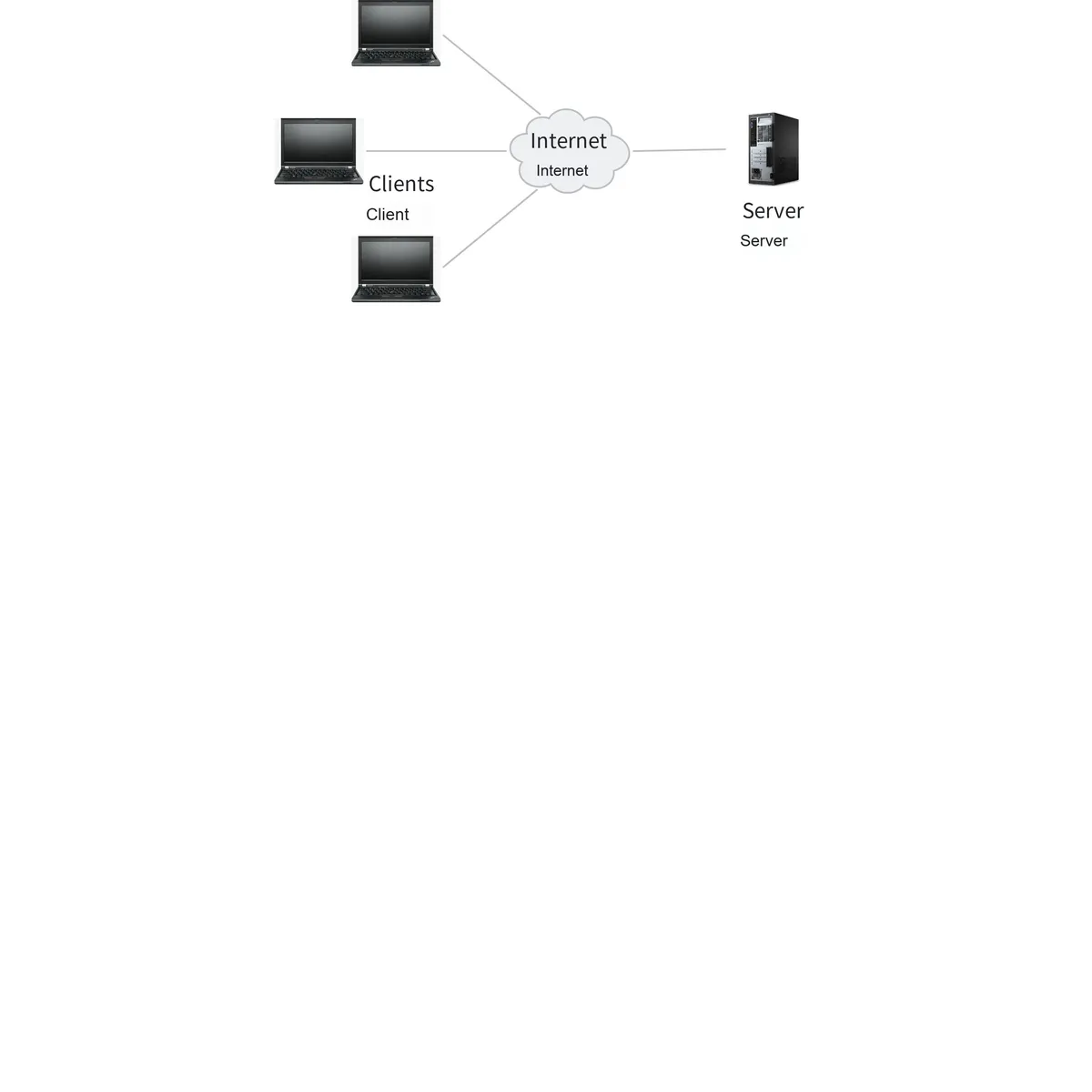
- Client: An application or device that requests information or services. A client sends requests to a server over a network and waits for the server's response.
- Server: An application or device that provides information or services. A server receives requests from the Client, processes the requests, and returns corresponding information or services.
The request-response model is one of the specific communication modes of the Client-server model. In this model, communication consists of a series of requests and responses:
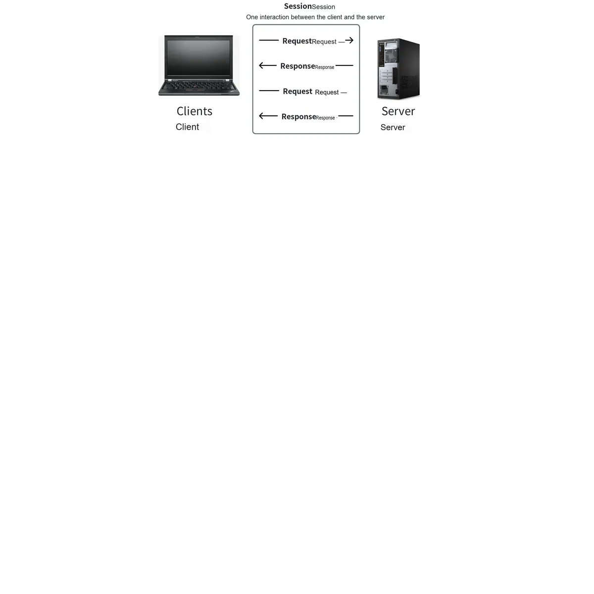
- Request: A request sent by a Client to the server, containing the operation to be performed or the data to be obtained.
- Response: The server processes the request and returns the result to the Client. A response can be the requested data, the result of an executed operation, or an error message.
In the request-response model, multiple request-response interactions constitute a session. For example, in web browsing, the interaction between a user and a web server can be regarded as a type of session:
- Client sends a request to the server: Request information: including the request type, target resource, parameters, etc. ;
- The server receives and processes the request: Process the request: perform corresponding operations (such as querying the database, calculating results) according to the request type and parameters;
- The server returns a response: Response information: including the operation result, requested data, status code, etc. ;
- Client receives and processes the response: Process the response: Perform corresponding operations based on the response information (such as displaying data and updating the interface).
3. Basic Functions of the Session Layer
In the OSI model, the Session Layer (Layer 5) is responsible for the establishment, management, and termination of sessions. Its main functions include:
- Session Control: manages the establishment, maintenance and termination of sessions
- Synchronization: Provides the synchronization function for data streams, such as setting checkpoints to enable recovery from the checkpoint when a session is interrupted
- Dialogue Control: Manages the direction of dialogue in full-duplex communication to prevent data collisions
The session layer and related protocols provide fault resolution procedures in communications to ensure reliability and data integrity. These procedures include:
- Error Detection and Correction: Use technologies such as checksum and Cyclic Redundancy Check (CRC) to detect and correct errors during transmission
- Retransmission Mechanism: If packet loss or corruption is detected, the session layer can request the retransmission of the lost or corrupted data packets.
- Timeout and Retry: If the expected response is not received within a specified period of time, the session layer can resend the request
- Session resumption: If a session is interrupted, the session layer can resume the session from the last synchronization point to avoid data loss.
4. Common Protocols in the Session Layer
At the fifth layer of the OSI model, namely the session layer, there are several common protocols and technologies used to manage and control network sessions. These protocols and technologies ensure the establishment, management and termination of communication sessions. Below are some examples of session layer protocols:
- NetBIOS (Network Basic Input Output System): NetBIOS is an API for network communication that provides session layer and presentation layer services, enabling applications to communicate within a Local Area Network (LAN).
- Key Functions:
- Provides session establishment and termination functions
- Supports session management and control
- Provides name services and datagram services, allowing applications to locate and access other computers on the network.
- Application Scenarios:
- It is mainly used for file and printer sharing in local area networks.
- Widely used in Microsoft networks for communication between Windows-based computers
- Key Functions:
- RPC (Remote Procedure Call Protocol): Remote Procedure Call Protocol (RPC) allows a program to invoke a program on another computer over the network as if it were calling a local program.
- Key Functions:
- enables the program to invoke remote services over the network
- Manage the establishment of sessions, data transmission, and session termination
- Provides synchronous and asynchronous communication mechanisms
- Application Scenarios:
- Application Communication in Distributed Computing Environments
- In network services and distributed systems, a Client invokes a service on a remote server
- Key Functions:
- PPTP (Point-to-Point Tunneling Protocol): Point-to-Point Tunneling Protocol (PPTP) is a protocol used for Virtual Private Networks (VPNs).
- Key Functions:
- Create secure, encrypted tunnels to transmit data over public networks such as the Internet
- Manage the establishment, maintenance and termination of tunnels
- Application Scenarios:
- Remote access VPN, which allows users to access corporate network resources through a secure tunnel
- Key Functions:
- SMB (Server Message Block): the Server Message Block Protocol (SMB) is used for sharing files, printers and serial ports over a network.
- Key Functions:
- Provide file and printer sharing services
- Manage the establishment and termination of sessions
- Supports file read and write operations and shared permission management
- Application Scenarios:
- File and Printer Sharing in Windows Networks
- File Sharing on NAS (Network-Attached Storage) Devices
- Key Functions:
1.1.3.7 OSI Presentation Layer
1. Basic Functions of the Presentation Layer
The sixth layer of the OSI model is the Presentation Layer. The main functions of the Presentation Layer include handling data formats, encryption and decryption, as well as data compression and decompression. It serves as the final layer for processing data before it is transmitted over the network, and also the first layer for processing data after it is received from the network and before it is delivered to the application program.
The main tasks of the presentation layer include:
- Data formatting: the process of converting data into a format recognizable by applications
- Data Encryption: Encrypt data to protect its security during transmission
- Data compression: the process of compressing data to reduce the size of data to be transmitted and improve transmission efficiency
- Data decompression: Decompress the received data to restore the original data format
- Data Access Control: controls access permissions to data to ensure data security
2. Data Formatting Method for the Presentation Layer- ASCII (American Standard Code for Information Interchange)
- Overview:
- ASCII is a 7-bit character encoding standard originally designed for information exchange. It defines 128 characters, including English letters, numerals, punctuation marks, and some control characters (such as line breaks).
- Features:
- A 7-bit binary number is used to represent a character, and the encoding range of each character is from 0 to 127
- ASCII encoding is widely used in text files and data exchange due to its strong compatibility and simplicity.
- Extension:
- ISO-8859-1 (also known as Latin-1) is a superset of ASCII, which extends the ASCII character set to include additional characters used in Western European languages, such as some supplementary symbols and letters.
- EBCDIC (Extended Binary-Coded Decimal Interchange Code)
- Overview:
- EBCDIC is a character encoding standard designed by IBM, mainly used in mainframe systems. It is an 8-bit encoding system and is not compatible with ASCII.
- Features:
- An 8-bit binary number is used to represent a character, and the encoding range of characters is from 0 to 255.
- EBCDIC is mainly used in outdated IBM mainframes and some host systems, so it is incompatible with modern computer systems and internet standards such as ASCII and Unicode.
- Application:
- It is mainly used for data processing and storage in mainframe environments.
- Unicode
- Overview:
- Unicode is a character encoding standard designed to provide unique codes for all writing systems. It supports multiple encoding forms, such as UTF-8, UTF-16 and UTF-32
- Features:
- UTF-8: A variable-length encoding that uses 1 to 4 bytes to represent a character, is compatible with ASCII, and is the most common Unicode encoding form.
- UTF-16: Uses two or four bytes to represent a single character, and can represent all Unicode characters
- UTF-32: It uses a fixed 4 bytes to represent a single character, supports all Unicode characters, simplifies character processing, but is relatively space-consuming.
- Application:
- Unicode enables text in different languages and character sets to be processed and displayed in a unified manner. It is widely used in modern computer systems, the Internet and software to support the character sets of multiple languages around the world.
- Overview:
- ASCII is a 7-bit character encoding standard originally designed for information exchange. It defines 128 characters, including English letters, numerals, punctuation marks, and some control characters (such as line breaks).
- Features:
- A 7-bit binary number is used to represent a character, and the encoding range of each character is from 0 to 127
- ASCII encoding is widely used in text files and data exchange due to its strong compatibility and simplicity.
- Extension:
- ISO-8859-1 (also known as Latin-1) is a superset of ASCII, which extends the ASCII character set to include additional characters used in Western European languages, such as some supplementary symbols and letters.
- Overview:
- EBCDIC is a character encoding standard designed by IBM, mainly used in mainframe systems. It is an 8-bit encoding system and is not compatible with ASCII.
- Features:
- An 8-bit binary number is used to represent a character, and the encoding range of characters is from 0 to 255.
- EBCDIC is mainly used in outdated IBM mainframes and some host systems, so it is incompatible with modern computer systems and internet standards such as ASCII and Unicode.
- Application:
- It is mainly used for data processing and storage in mainframe environments.
- Overview:
- Unicode is a character encoding standard designed to provide unique codes for all writing systems. It supports multiple encoding forms, such as UTF-8, UTF-16 and UTF-32
- Features:
- UTF-8: A variable-length encoding that uses 1 to 4 bytes to represent a character, is compatible with ASCII, and is the most common Unicode encoding form.
- UTF-16: Uses two or four bytes to represent a single character, and can represent all Unicode characters
- UTF-32: It uses a fixed 4 bytes to represent a single character, supports all Unicode characters, simplifies character processing, but is relatively space-consuming.
- Application:
- Unicode enables text in different languages and character sets to be processed and displayed in a unified manner. It is widely used in modern computer systems, the Internet and software to support the character sets of multiple languages around the world.
3. Network Security Protocol
SSL (Secure Sockets Layer) and TLS (Transport Layer Security) are network security protocols designed to encrypt communications over computer networks and ensure the security of data during transmission. TLS is the successor to SSL; while the two share many similarities, TLS delivers stronger security and more functional improvements.
SSL (Secure Sockets Layer) is the earliest encryption protocol, developed by Netscape. It is primarily used to protect the confidentiality and integrity of network communications. SSL achieves secure communication by encrypting data streams, preventing data tampering, and authenticating the identities of both communicating parties.
There are two versions of the SSL protocol:
- SSL 2.0 (1995): The earliest version, which had several security vulnerabilities
- SSL 3.0 (1996): It improved upon SSL 2.0, but also had several known security vulnerabilities.
TLS is the successor to SSL and was developed by the Internet Engineering Task Force (IETF). TLS improves upon the security of SSL and provides stronger encryption algorithms and authentication methods. The TLS protocol ensures the confidentiality, integrity, and authentication of data transmission.
There are four versions of the TLS protocol:
- TLS 1.0 (1999): Based on SSL 3.0 with improvements made
- TLS 1.1 (2006): Further enhanced security and fixed some issues in TLS 1.0
- TLS 1.2 (2008): added support for stronger encryption algorithms and improved the security of the protocol
- TLS 1.3 (2018): Simplified the handshake process, delivers stronger encryption and faster performance, and improves security and privacy protection
The SSL and TLS encryption and decryption process is as follows:
- Handshake Phase:
- The Client and the server establish a secure connection and exchange encryption algorithm and key information
- The server presents its digital certificate, and the Client verifies the validity of the certificate
- The two parties negotiate the encryption algorithm and generate a session key, which is used to encrypt the actual data
- Encryption Phase (Data Transfer Phase):
- Client and server use the negotiated encryption algorithm and session key to encrypt and decrypt data
- Securely transmit data over the network to prevent eavesdropping and tampering
- Termination Phase:
- The client and server terminate the session and release the relevant resources
1.1.3.8 OSI Application Layer
1. Basic Functions of the Application Layer
The seventh layer of the OSI model is the Application Layer. As the topmost layer in the OSI model, the Application Layer directly provides network services for users' application programs. It handles the interaction between applications and the network, and delivers functions that serve as a direct interface for both end users and applications. Here, applications refer to software programs installed on the operating system, such as web browsers (e. g., Firefox) and word processors (e. g., Microsoft Word). Certain applications run dedicated network functions in the background.For example, Mail User Agent programs use the SMTP, POP3, or IMAP protocols to send and receive email over the network. All of these protocols operate at the application layer to ensure the proper transmission of email.
The main functions of the application layer are as follows:
- Network Services: Services related to network communications, such as email, file transfer, and web browsing, etc.
- Protocol Support: Supports various application-layer protocols, which define how applications communicate over the network
- Data formatting: the process of formatting data generated by an application into a format suitable for network transmission
- User Interface: Provides a user interface for web applications, enabling users to perform operations via the network
- Session Management: It manages and controls the establishment, maintenance and termination of sessions. Although this is mainly implemented at the session layer, the application layer usually interacts with session management.
2. Common Protocols in the Application Layer
The application layer encompasses a variety of protocols that support different types of network applications and services:
- FTP (File Transfer Protocol)
- It is used for file transfer over the network, and supports functions such as file upload and download, as well as file management (e. g. deletion and renaming).
- SSH (Secure Shell)
- It provides secure remote access and management capabilities, allowing users to log in to another computer remotely via an encrypted channel to execute commands and manage the system.
- SMTP (Simple Mail Transfer Protocol)
- It is used to send emails and defines how mail servers send and forward emails.
- IMAP (Internet Message Access Protocol)
- It is used to access and manage emails from the mail server, supports saving emails on the server, and provides flexible access to and management of emails.
- DNS (Domain Name System)
- It converts domain names into IP addresses, allowing users to access network resources via domain names. It supports functions such as domain name resolution, load balance and Service Discovery
- HTTP (Hypertext Transfer Protocol)
- It is used for web browsing and data transmission, and defines the request and response process between the Client (browser) and the server.
1.1.4 TCP/IP Model
The TCP/IP model is the standard model of the Internet protocol suite and is commonly used to describe the structure of protocols in modern networks. As a more streamlined model, it has fewer layers than the OSI model and is closer to practical applications.
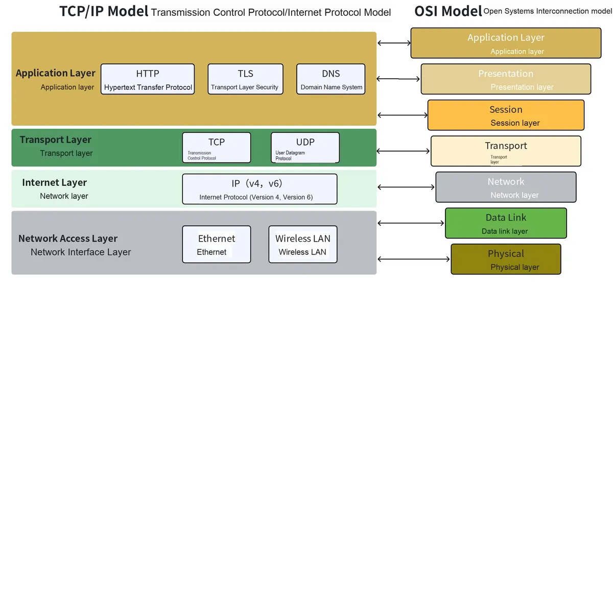
The TCP/IP model consists of four main layers, which are as follows:
- Network Access Layer: responsible for transmitting data frames over local area networks
Included protocols and standards:
- Ethernet: A frame transmission standard for local area networks
- Wi-Fi (IEEE 802.11): a standard for wireless local area networks
- PPP (Point-to-Point Protocol): Used for point-to-point connections, such as dial-up networks
- ARP (Address Resolution Protocol): maps IP addresses to physical addresses (MAC addresses)
- VLAN (Virtual Local Area Network): Used for logical division and isolation of networks
- Internet Layer: Responsible for routing and forwarding data packets, and managing communication between IP addresses and networks.
Included protocols:
- IP (Internet Protocol): Defines the addressing and routing of data packets, and is divided into IPv4 and IPv6
- ICMP (Internet Control Message Protocol): Used to send control messages and error reports, such as Ping and Traceroute.
- IGMP (Internet Group Management Protocol): Used for multicast communication to manage host groups
- RARP (Reverse Address Resolution Protocol): maps physical addresses to IP addresses
- Transport Layer: Provides end-to-end communication services to ensure reliable data transmission over the network.
Included protocols:
- TCP (Transmission Control Protocol): Provides connection-oriented and reliable data transmission, and handles data flow control and error recovery.
- UDP (User Datagram Protocol): Provides connectionless data transmission and is suitable for latency-sensitive applications.
- SCTP (Stream Control Transmission Protocol): It provides multi-stream data transmission and is applicable to applications requiring multiple flow control mechanisms.
- Application Layer: Provides protocols that directly interact with users and application programs, and supports various network application services.
Included protocols:
- HTTP/HTTPS (Hypertext Transfer Protocol/Secure): Used for web browsing and data transmission
- FTP/FTPS (File Transfer Protocol/Secure): Used for file transfer
- SMTP (Simple Mail Transfer Protocol): used for sending emails
- IMAP (Internet Message Access Protocol) and POP3: Used for receiving and managing emails
- DNS (Domain Name System): Converts domain names to IP addresses
- Telnet and SSH (Secure Shell): Used for remote login and management
- SNMP (Simple Network Management Protocol): used for the management and monitoring of network devices
In the TCP/IP model, the network interface layer is responsible for encapsulating data into frames and transmitting them over the local network, while also handling network interfaces, error detection and physical addresses; the network layer segments data into packets and adds IP addresses to them, and handles the routing and forwarding of packets across different networks; the transport layer uses TCP or UDP protocols to handle end-to-end data transmission; the application layer provides specific application services and protocols, processes user requests and services, and ensures that applications can communicate properly over the network.
From the above explanation of the OSI model and TCP/IP model, it is not difficult to see that to reduce the complexity of network design, network models adopt a layered design approach to encapsulate hardware and software; each layer has its own tasks and interfaces, the upper layer can call the services provided by the lower layer, and the details within each layer can be implemented independently without mutual interference.
1.1.5 Detailed Explanation of ETH Ethernet Protocol
Ethernet is the most widely used wired local area network standard in Internet technologies, and many people equate it with the Internet itself. In fact, Ethernet (ETH) is only one type of local area network. Ethernet is based on the IEEE 802.3 standard, which mainly covers the physical layer and the MAC sublayer of the data link layer. Apart from Ethernet (ETH), IEEE has also defined other local area network standards:
- IEEE 802.11 - Wireless Local Area Network (Wi-Fi):
- Wi-Fi: A wireless local area network technology that defines the physical layer and data link layer protocols for wireless networks, covering various versions such as 802.11a/b/g/n/ac/ax
- IEEE 802.15 - Wireless Personal Area Network (WPAN):
- Bluetooth: a personal area network (PAN) technology for short-range wireless communication
- ZigBee: A low-power, low-data-rate wireless communication technology based on IEEE 802.15.4, which is widely used in Internet of Things (IoT) applications
- IEEE 802.17 - Resilient Packet Ring (Resilient Packet Ring):
- defines the technologies for wireless broadband access
- IEEE 802.16 - Broadband Wireless Access (WiMAX):
- It is an Ethernet standard that defines a ring network structure, featuring high reliability and low-latency data transmission.
Common Ethernet types in the IEEE 802.3 standard are as follows: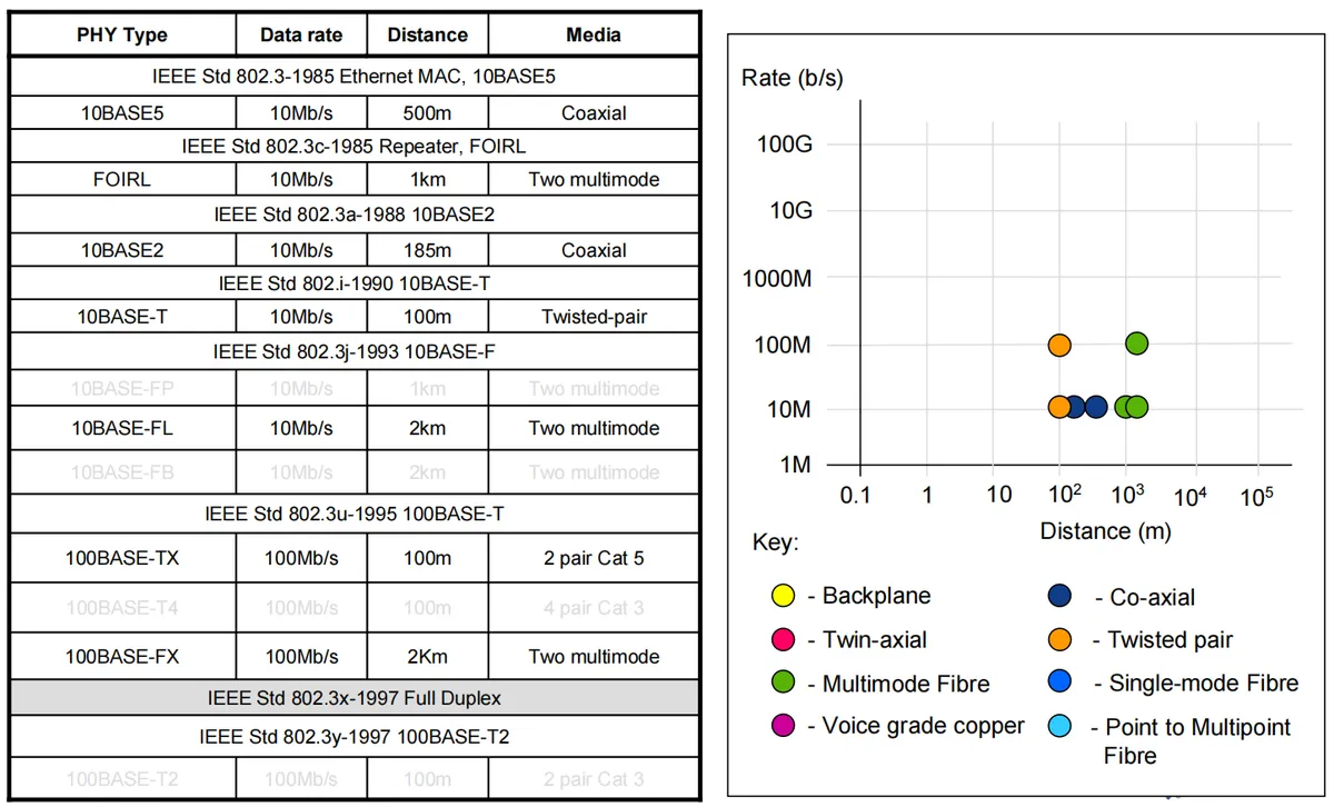
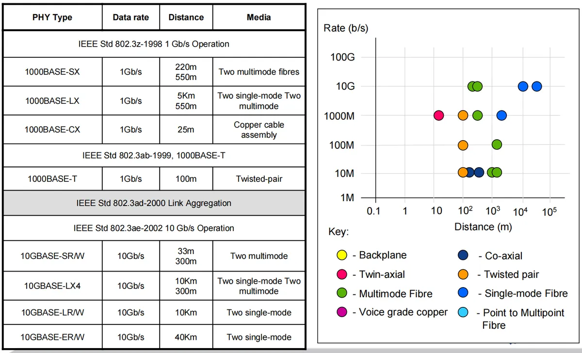
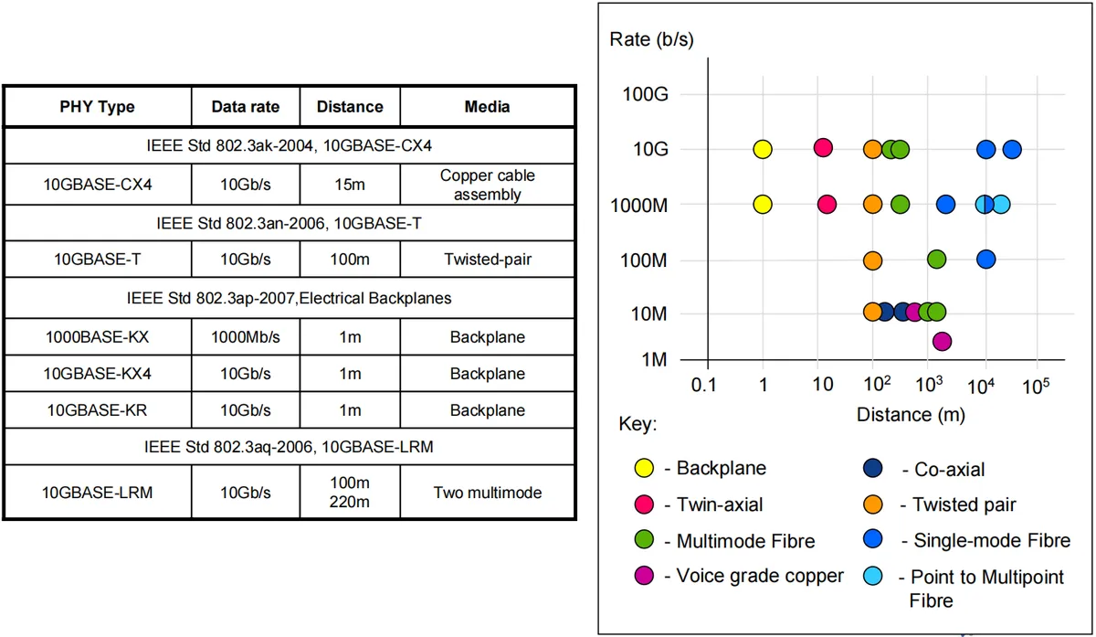
- 10BASE-T/100BASE-TX: This is the most common Ethernet standard, which uses twisted-pair copper cables; 10BASE-T offers a transmission rate of 10Mbps, while 100BASE-TX provides 100Mbps
- Gigabit Ethernet (1000BASE-T): It provides high-speed Ethernet transmission at 1000Mbps (1Gbps) and also uses twisted-pair copper cables as the physical medium.
- 10 Gigabit Ethernet (10GBASE-T): It enables ultra-high-speed Ethernet transmission at 10Gbps and requires the use of high-performance twisted pair cables or optical fibers.
- Fast Ethernet: including fiber optic Ethernet standards such as 100BASE-FX and 100BASE-SX, provides a transmission rate of 100Mbps, and is suitable for long-distance networks.
1.1.5.1 Physical Layer
1. Transmission Medium
Common transmission media for Ethernet include the following types: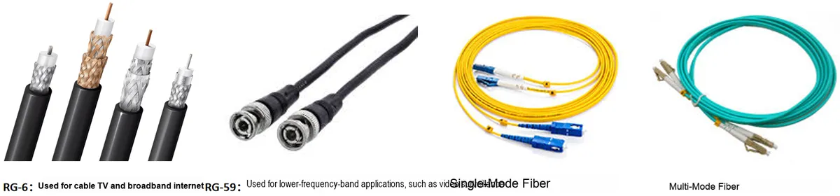
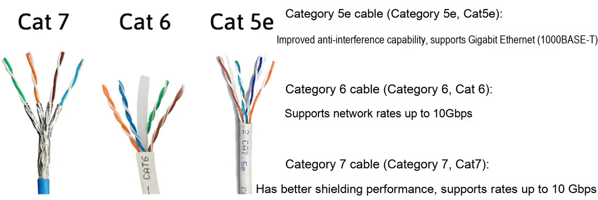
- Coaxial Cable: Consists of a central conductor, an insulating layer, a braided metal shielding layer, and an outer insulating layer
- Twisted Pair Cable: Two insulated copper wires twisted together to reduce interference and crosstalk
- Fiber Optic Cable: Consists of a fiber core, cladding, and protective layer
The differences between different types of twisted pair cables are as follows:
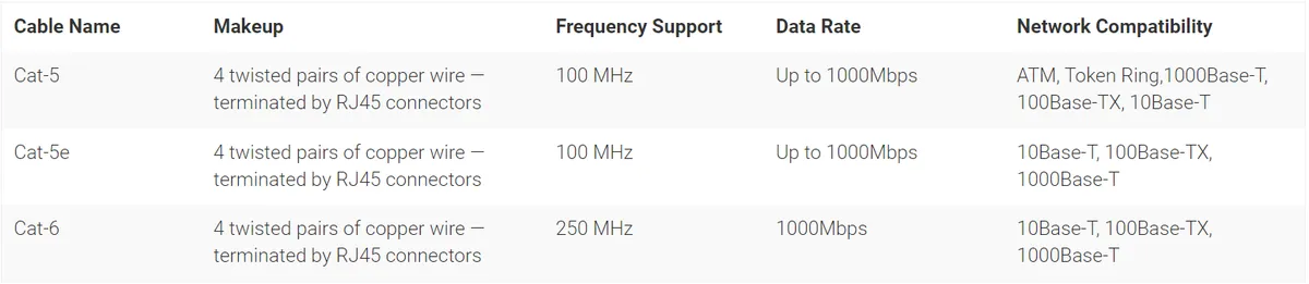
The Ethernet data transmission medium we use most commonly is UTP network cable, which consists of a certain length of unshielded twisted pair and RJ45 connectors. The twisted pair is composed of 8 wires of different colors twisted together in 4 pairs, and the purpose of twisting the wires in pairs is to minimize the impact of electromagnetic radiation and external electromagnetic interference as much as possible.
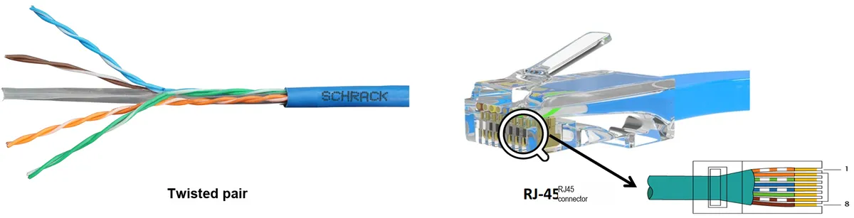
Different devices can be connected via UTP network cables to their respective network ports or to the same switch to form a data transmission loop:
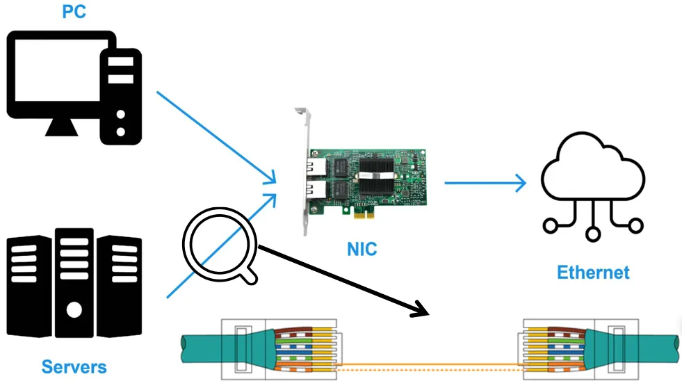
The RJ45 connector has 8 pins, and each pin serves a specific purpose under the standard wiring scheme:
- Tx+(Transmit Positive) and Tx-(Transmit Negative): the positive and negative signal lines for transmitting data
- Rx+(Receive Positive) and Rx-(Receive Negative): the positive and negative signal lines for receiving data
There are two commonly used pinout standards: T568A and T568B.
- T568A standard
Pin No.  Signal Name  Color
1        Tx+       White-green
2        Tx-       Green
3        Rx+       White-orange
4        -         Blue
5        -         White-blue
6        Rx-       Orange
7        -         White-brown
8 - Brown- T568B Standard
Pin No.  Signal Name  Color
1        Tx+       White-orange
2        Tx-       Orange
3        Rx+       White-green
4        -         Blue
5        -         White-blue
6        Rx-       Green
7        -         White-brown
8        -         Brown
There are two wiring sequences for RJ45 connectors: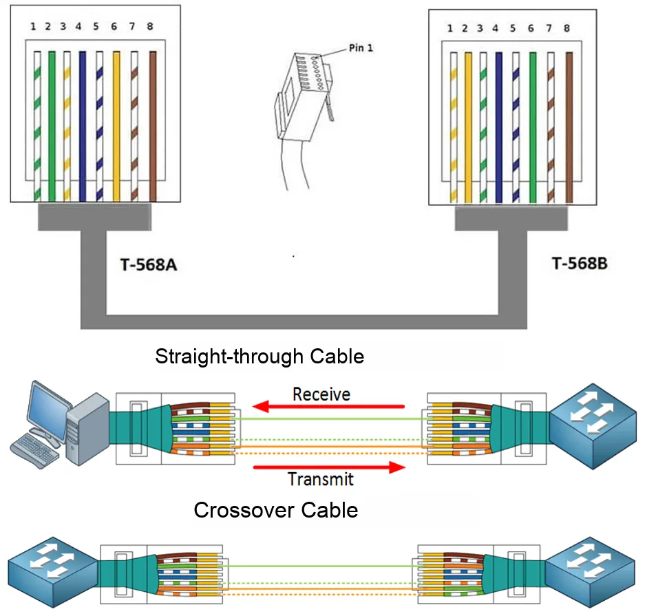
- Straight-through Cable: A cable with identical pin configurations at both ends (e. g., both ends following the T568A standard or both following the T568B standard), which is used to connect devices of different types, such as a computer and a switch.
- Crossover Cable: A cable with different pin configurations at both ends (e. g., T568A at one end and T568B at the other), which is used to connect devices of the same type, such as two computers.
For Gigabit full-duplex Ethernet (1000BASE-TX), the situation is different: it uses all 4 wire pairs and is capable of transmitting and receiving simultaneously over each wire pair.

There are two indicator lights on the RJ45 connector, which are used to indicate the network signal and connection status:
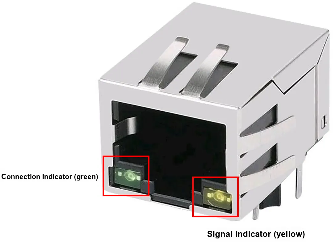
The meanings of the indicator lights are as follows:
- Link Indicator Light (Link Light, Green/Orange):
When the connection indicator light is on, it means the line is connected properly.
- Activity Light (Yellow/Green): When the connection indicator is on, the meaning of the activity light is as follows:
- If the signal indicator light is flashing, it indicates that the signal is normal and communication is in progress.
- If the signal indicator light is off, it means there is no communication.
- If the signal indicator stays on steadily, it indicates a short circuit in the network cable.
Meaning of Ethernet Standards:
We often come across terms related to Ethernet standards such as 100BASE-T and 10BASE-T in technical materials, and here we provide an interpretation of them:
Taking 1000BASE-TX as an example, where:
- 1000: indicates that the maximum transmission rate is 1000 Mbps (1 Gbps); if the value is 10, the maximum transmission rate is 10 Mbps.
- BASE: stands for baseband transmission, which means that the signal exclusively occupies the entire frequency band of the transmission medium for data transfer.
- T: Indicates that a twisted pair is used as the transmission medium.
- X: stands for full-duplex cable; if it is FL, it indicates optical fiber
2. Ethernet Coding
Ethernet coding plays a crucial role in Ethernet communication, which is mainly used to ensure that data can be reliably transmitted over physical media and accurately decoded at the receiving end. Ethernet adopts different coding technologies, and the coding methods vary according to different standards and transmission rates. The following are some common Ethernet coding technologies:
- 10BASE-T Ethernet: It adopts Manchester encoding, where each bit has a transition in the middle of the clock cycle: logic 0 is represented by a high-to-low transition, and logic 1 is represented by a low-to-high transition
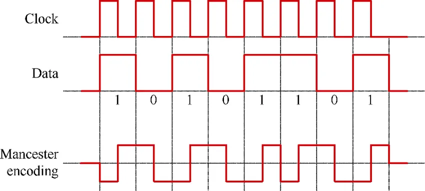
- 100BASE-TX Ethernet: It adopts 4B/5B encoding, which encodes 4-bit data into 5-bit codewords to ensure sufficient transitions in each codeword; the 5-bit codewords are further transmitted via MLT-3 (Multi-Level Transmission, 3-level).
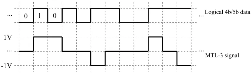
- 1000BASE-T Ethernet: It adopts 4D-PAM5 encoding, uses 4 twisted pairs, and employs 5-level Pulse Amplitude Modulation (PAM5) on each pair of cables for simultaneous transmission over the four twisted pairs; each cable pair transmits 2 bits of data, thus achieving 8 bits of data transmission per symbol.
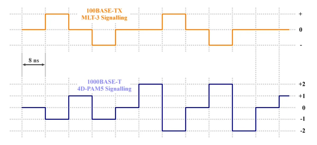
3. Deterministic MAC and Non-deterministic MAC
In the Medium Access Control (MAC) sublayer, medium access control methods can be classified into two major categories: deterministic and non-deterministic. The primary differences between these two methods lie in the timing and scheduling of data transmission: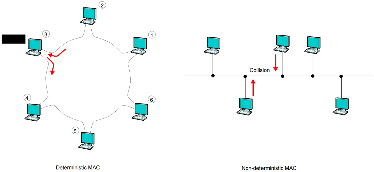
- Deterministic MAC Method: It guarantees that the timing of data transmission is deterministic, meaning that each device gets the opportunity to access the network within a specific time window. This method is suitable for application scenarios that require strict time control, such as industrial control systems and real-time communication systems. We can implement deterministic MAC using token ring or time division multiple access.
- Non-deterministic MAC methods: They do not guarantee the timing of data transmission, as devices contend for the Right of access to the network, which may result in uncertain transmission delays. They are suitable for general data communication scenarios, such as Ethernet and wireless local area networks. We can use CSMA/CD or CSMA/CA methods to avoid conflicts arising from device communication.
4. CSMA/CD Carrier Sense and Collision Detection Mechanism
Here, we take the data transmission and reception of an Ethernet hub as an example to explain the CSMA/CD (Carrier Sense Multiple Access with Collision Detection) mechanism. In the 1990s, Ethernet hubs were commonly used to connect multiple computers for communication (multiple nodes are connected to the same network bus, forming a bus-type network). When data is transmitted to the hub from one port, the hub broadcasts the signal from all ports until the destination device receives it. However, when it receives multiple data streams (assuming there is no CSMA/CD mechanism), it will lead to network collisions:
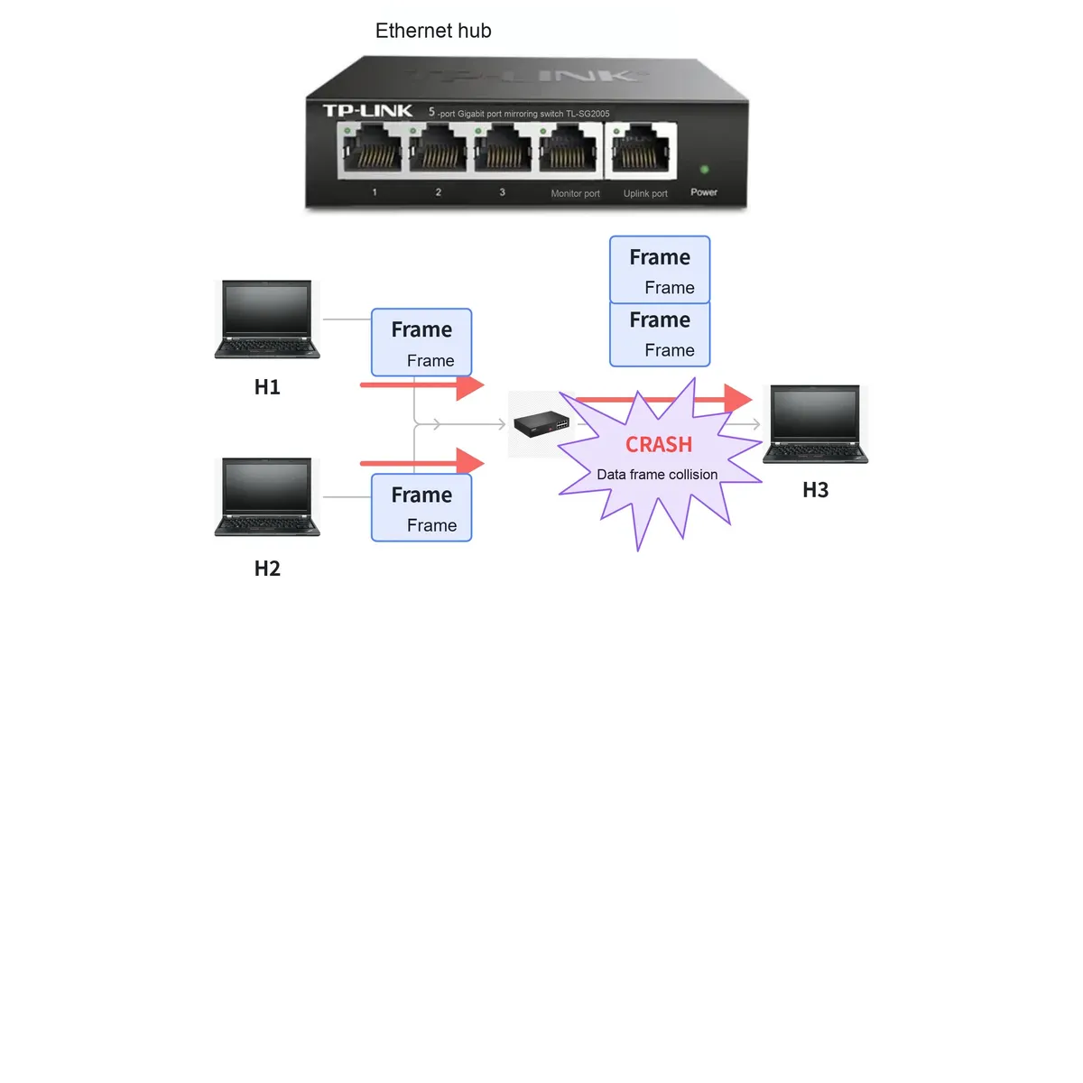
To address this issue, we must adopt the half-duplex transmission mode: half-duplex means that transmission and reception cannot be performed simultaneously. When one computer is transmitting, all other computers have to wait; when no device is transmitting, any device may initiate transmission. However, communication collisions will still occur if two computers both determine that "the line is idle" and start transmitting at the same time.
To address this issue, researchers have adopted the CSMA/CD mechanism, and the main content of the CSMA/CD protocol is as follows: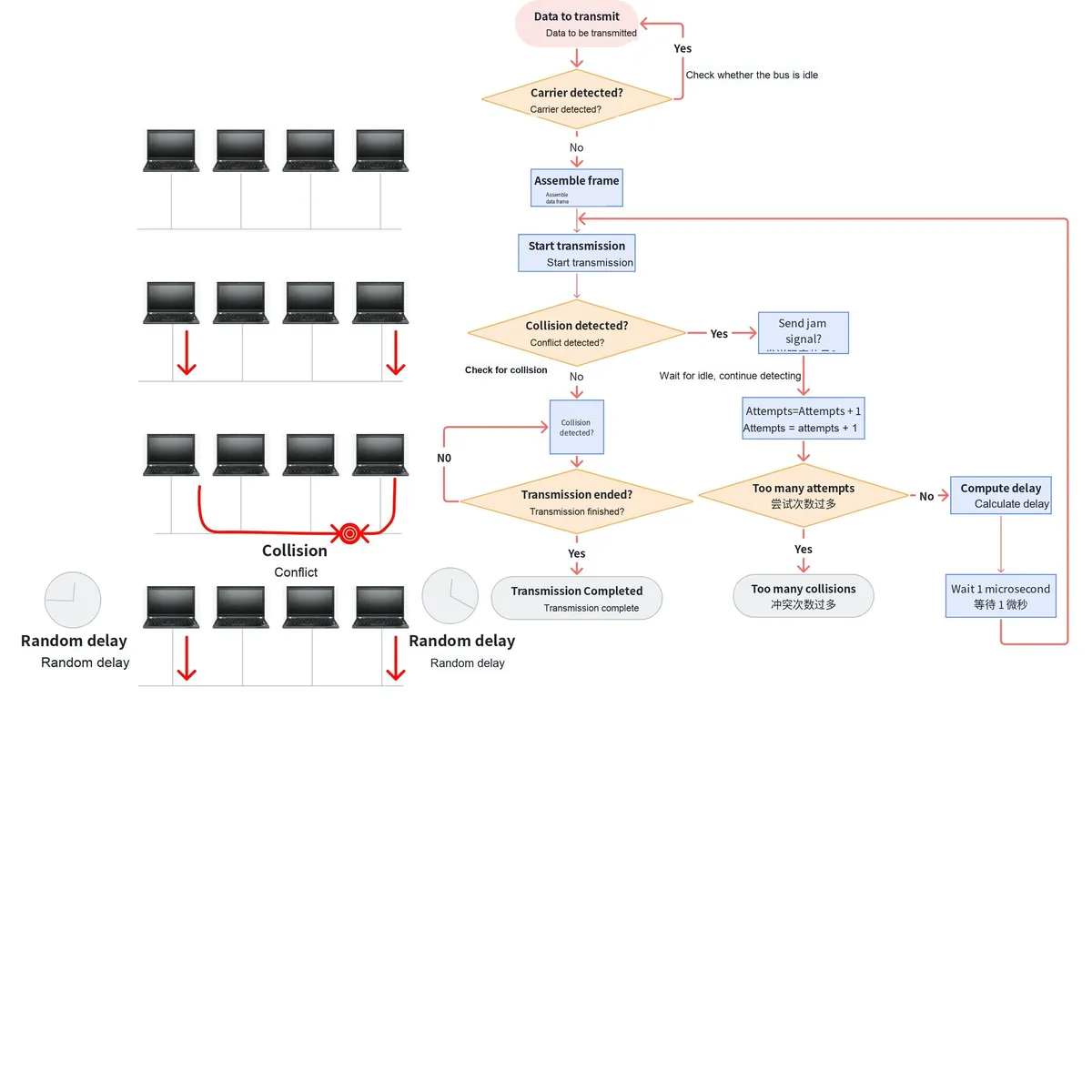
- Carrier Sense
- Before transmitting data, the network card first detects whether there are other devices transmitting data on the network cable (carrier detection).
- If it detects that another device is transmitting data, it will defer its own data transmission to avoid collisions.
- Multiple Access
- Ethernet allows multiple devices to share the same network cable for data transmission
- Each device can transmit data independently without the need for central scheduling.
- Collision Detection
- If two devices start transmitting data at the same time, a collision will occur.
- Upon detecting a collision, the device will immediately stop transmission and retry after a random period of time.
Simply put, the working principle of CSMA/CD is as follows: in a shared Ethernet, a device first listens to check whether the channel is idle before transmitting data; if the channel is idle, it transmits data and meanwhile sets a timer to guard against collisions; if the channel is busy, it waits for a random period of time before retrying; if collisions still occur after multiple attempts, it abandons the transmission and reports an error.
In modern Ethernet networks, hubs have been replaced by switches. Switches connect devices via independent ports, enabling full-duplex communication and avoiding collisions. Specifically, they can read Ethernet frames and forward them only to the devices that need them. When there are two frames to be forwarded on a port, the switch can queue the second one to prevent conflicts.
5. Common Ethernet Error Types
Ethernet is one of the core technologies of modern network communication, yet various errors may occur during its actual operation. The following are common Ethernet error types and their descriptions:
- Collision: A collision occurs when two or more devices attempt to transmit data simultaneously. This is particularly common in half-duplex Ethernet networks (such as networks using hubs).
- Frame Error: A data frame gets corrupted during transmission, resulting in a mismatch of the frame's checksum (e. g., FCS).
- Jumbo Frame: A data frame that exceeds the standard Ethernet frame length (1518 bytes)
- Runt Frame: A frame with a length of less than 64 bytes, usually caused by collisions or hardware failures
- CRC Error (Cyclic Redundancy Check Error): The CRC checksum of the frame does not match, indicating that the data has been corrupted during transmission.
- Dropped Frame: When the buffer of a switch or router is full, data frames are discarded
- Duplex Mismatch: A situation where the two ends of a network are configured with different duplex modes, with one port operating in full-duplex mode and the other in half-duplex mode
6. Auto-negotiation
Auto-Negotiation is a feature defined in Ethernet standards that automatically determines the optimal connection parameters, such as speed and duplex mode, between Ethernet devices. This function helps ensure that network devices communicate at their best performance while reducing manual configuration errors.
The workflow of Auto-Negotiation is as follows: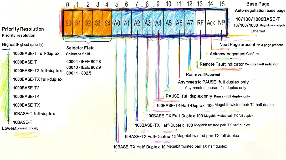
- Initial Connection: When two network devices (such as a computer and a switch) are connected, they exchange Auto-Negotiation frames through the Physical Layer (PHY) to initiate the auto-negotiation process.
- Capability exchange: Each device transmits capability frames containing the supported speed and duplex mode, and these frames are referred to as Fast Link Pulses (FLPs).
- Select the optimal configuration: The two devices select the highest mutually supported speed and the optimal duplex mode (full-duplex or half-duplex) based on their respective capability frames.
- Set connection parameters: The devices configure their respective interfaces according to the negotiation result and start data communication
7.5-4-3 Rule
The 5-4-3 rule is a provision in Ethernet standards, applicable to shared-medium Ethernet (such as networks using coaxial cables or hubs). It defines the constraints of network topology to ensure effective signal transmission and collision detection.
Simply put, the 5-4-3 rule is as follows: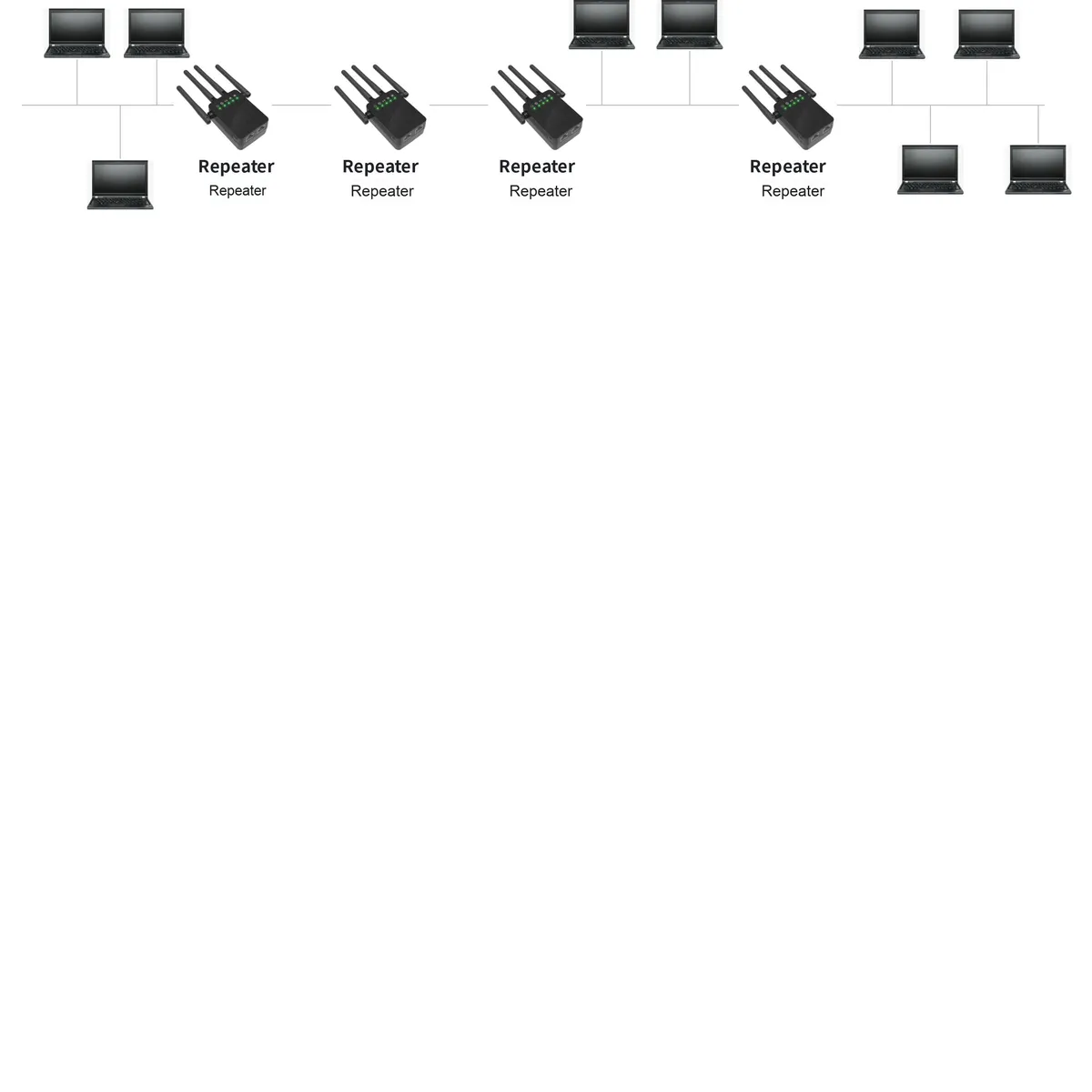
- 5 Cable Segments (5 Segments): In a network, there can be a maximum of 5 cable segments (also referred to as physical segments or collision domains)
- 4 Repeaters: A maximum of 4 repeaters (hubs or transponders) can be connected between these cable segments; these devices are used to extend network coverage but will also introduce latency.
- 3 Populated Segments (segments with nodes): Among these 5 cable segments, a maximum of only 3 can be connected to terminal nodes (such as computers, printers, etc.), while the remaining 2 can only be used for signal extension (i. e., repeater segments)
Ethernet relies on the CSMA/CD protocol (Carrier Sense Multiple Access with Collision Detection) to handle collisions in the network. The 5-4-3 rule ensures that the signal transmission time within the collision domain falls within the specified range, so as to effectively detect and handle collisions. Meanwhile, limiting the number of repeaters and cable segments can reduce signal attenuation and delay, thus guaranteeing the integrity and reliability of signals in the network.
However, with the popularization of full-duplex Ethernet and switches, the 5-4-3 rule is no longer applicable in modern Ethernet networks. Switches eliminate collision domains, with each port forming an independent collision domain and supporting full-duplex communication, which makes network design more flexible and no longer restricted by the traditional 5-4-3 rule.
8. Segments and Micro-segments
A traditional Ethernet network consists of a single segment, and data transmitted over the network is received by all stations connected to it. As the number of stations connected to the network increases, the number of collisions also rises accordingly. To avoid performance degradation, the network can be segmented using switches.
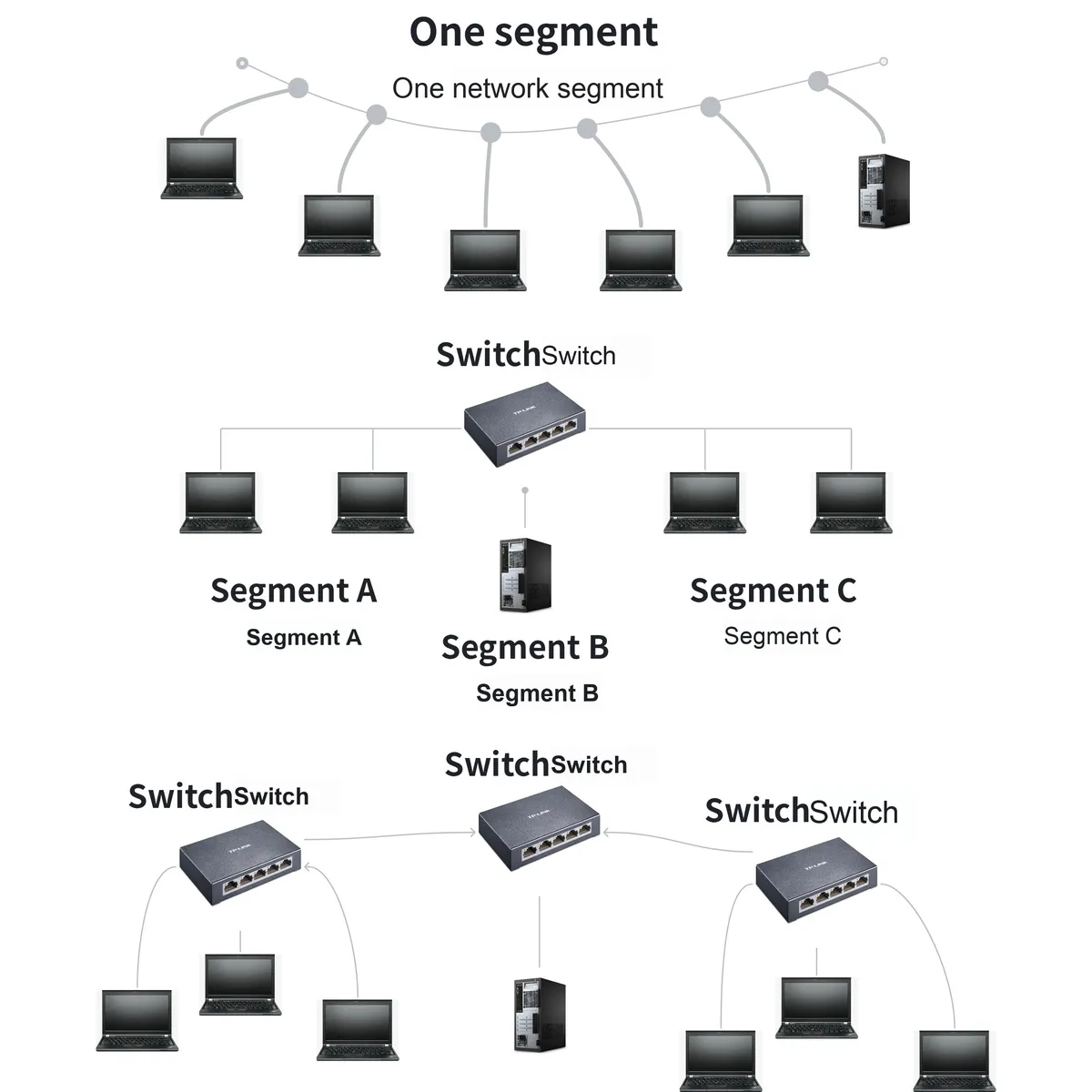
Segmentation refers to the process of dividing a large network into multiple smaller subnets or zones, while microsegmentation is an advanced form of network segmentation designed to implement fine-grained segmentation for each device, application or workload in the network.
9. VLAN (Virtual Local Area Network)
VLAN (Virtual Local Area Network) is a networking technology that enables the creation of logically independent subnets over a physical network.
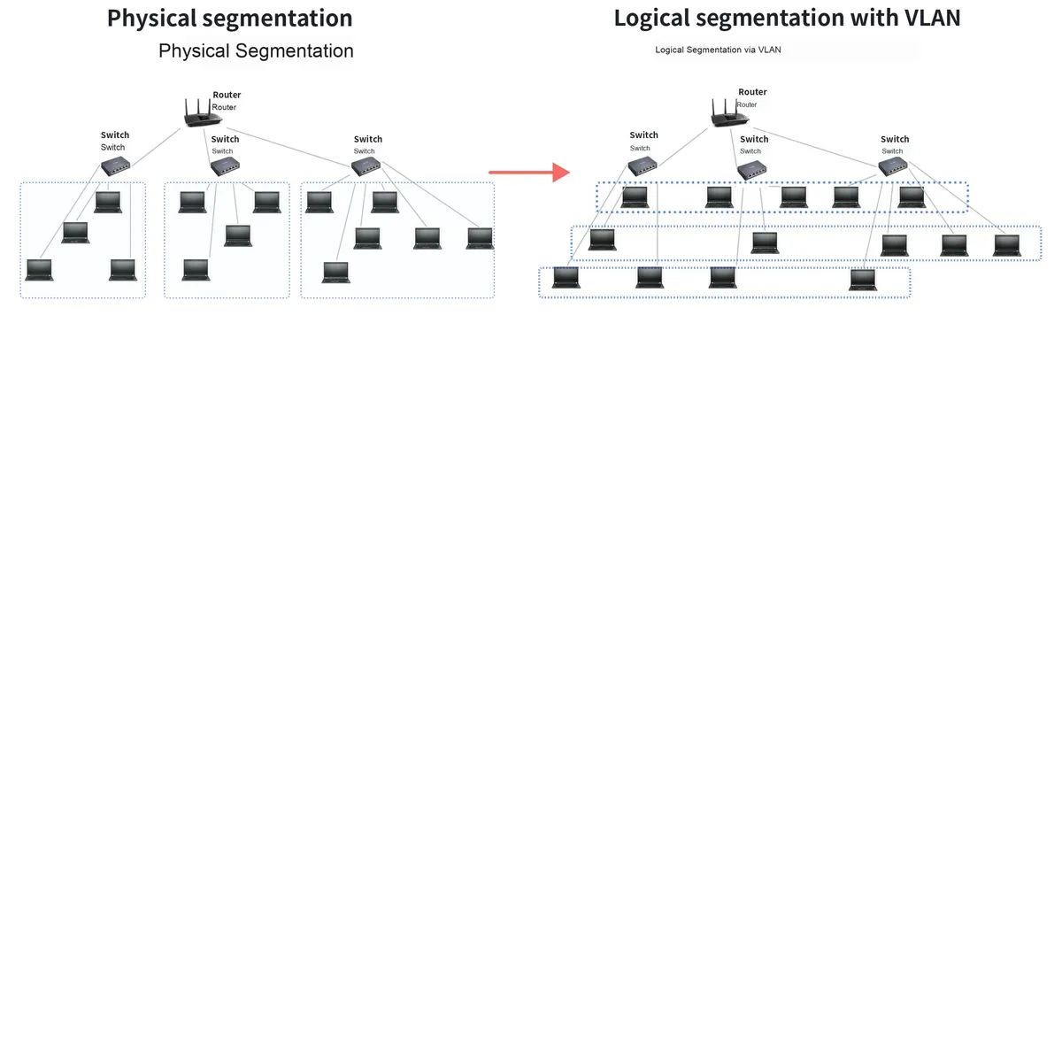
Bridging devices typically forward broadcast traffic to all connected network segments. This can lead to broadcast storms, where broadcast packets circulate continuously and degrade network performance, especially in large-scale networks. By tagging data frames at the data link layer, VLANs ensure that devices in different VLANs do not broadcast to other VLANs even when they are physically connected. This approach enhances security, prevents broadcast storms, and improves the flexibility and manageability of the network.
Although VLANs can divide a large network into multiple smaller broadcast domains, traditional bridging still requires maintaining a MAC address table for each VLAN, which may lead to increased resource consumption and management complexity. Meanwhile, traditional bridging devices cannot implement complex access control policies between VLANs.
1.1.5.2 Data Link Layer
According to the IEEE 802.3 standard, the data link layer can be divided into the MAC layer and the LLC layer: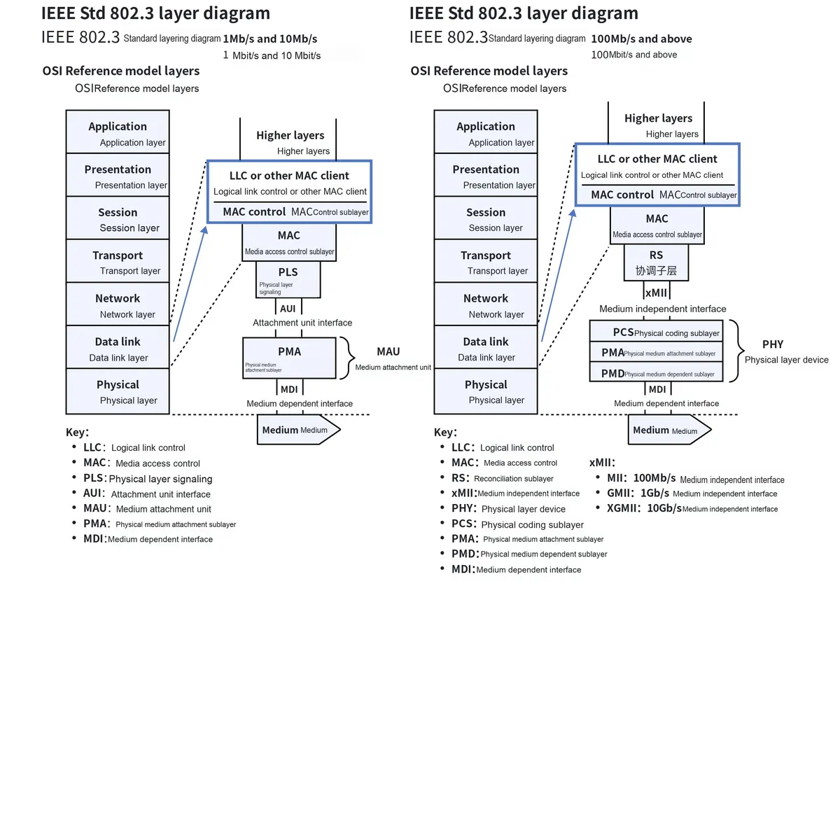
- LLC Logical Link Control Sublayer (Logical Link Control): It is located in the upper part of the data link layer, responsible for functions such as data frame synchronization, flow control and error detection, and provides a unified data link service interface for upper layers
- MAC Media Access Control Sublayer (Media Access Control): Located in the lower sublayer of the data link layer, it is responsible for solving the media access problem of multiple devices sharing a single channel, implementing media access mechanisms such as CSMA/CD and CSMA/CA, and meanwhile providing the functions of data frame addressing and error check.
In practical network devices, the network interface card on the PC side is responsible for implementing the functions of the MAC layer and the physical layer, while the protocol stack of the operating system implements the LLC layer and higher-layer protocols. In embedded devices, the MAC layer and the physical layer may also be integrated into a single chip.
1. MAC Media Access Control Sublayer
The MAC sublayer is a component of the data link layer, which is mainly responsible for transmitting data frames between network nodes and processing the raw bit streams transmitted from the physical layer. It provides functions such as data frame encapsulation/decapsulation, error detection, flow control and physical address addressing, ensuring the stable operation of the data link layer and efficient data transmission.
MAC packets (also referred to as MAC frames) are the fundamental unit used by the data link layer for data transmission. A typical MAC frame consists of the following components: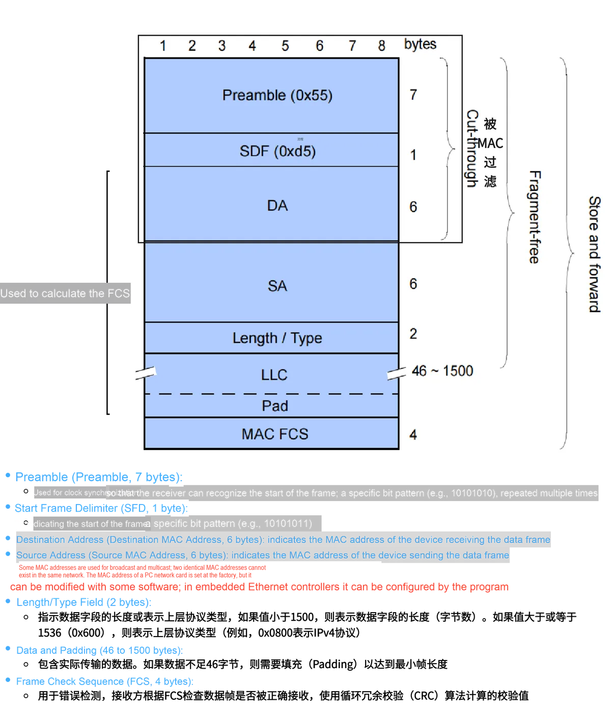
- Preamble: used for frame synchronization
- Start Frame Delimiter (SFD): indicates the start position of a frame
- Destination MAC Address: The MAC address of the device that receives the data frame
- Source MAC Address: The MAC address of the device that transmits the data frame
- Length/Type Field: indicates the length of the data field or represents the type of the upper-layer protocol
- Data and Padding: The data field contains the actually transmitted data, and the padding field ensures the minimum length of the frame
- Frame Check Sequence (FCS): Used for error detection
Suppose we have a simple MAC frame, with the contents of its fields as follows:
- Preamble:
10101010repeated 7 times - SFD:
10101011 - Destination Address:
00:14:22:01:23:45 - Source Address:
00:16:36:29:48:01 - Type field:
0x0800(indicating IPv4) - Data: Actual data content
- Padding: Add 0 bytes if padding is required
- FCS: the CRC value obtained through calculation
The structure of this MAC frame is as follows:
+-----------+---------+-----------------+---------------+------------+---------------------+-----+
| 10101010  | 10101011| 00:14:22:01:23:45| 00:16:36:29:48:01| 0x0800   | Actual data         | CRC |
| 10101010  |         |                 |               |           | (and padding, if needed)|     |
| ... (7 times)       |                 |               |           |                     |     |
+-----------+---------+-----------------+---------------+------------+---------------------+-----+
In addition to standard MAC data packets, there are extended MAC data packets (also referred to as VLAN-tagged MAC data packets or IEEE 802.1Q frames) that support Virtual Local Area Networks (VLANs). These extended packets add a 4-byte QTag prefix field to the standard MAC packet, and the QTag field is located between the source MAC address (SA) and the packet type field.
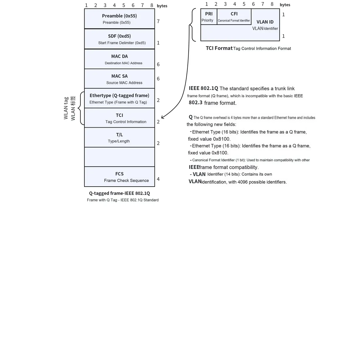
The QTag prefix field consists of the following parts:
- Tag Protocol Identifier (TPID) – 2 bytes: a fixed value
0x8100, used to identify that this frame contains a QTag prefix. - Tag Control Information (TCI) - 2 bytes:
including the following contents:
- User Priority (Priority) – 3 bits: Defines the priority of the frame.
- Canonical Format Indicator (CFI) – 1 bit: usually set to 0 (for Ethernet).
- VLAN Identifier (VLAN ID) – 12 bits: Identifies the VLAN to which the frame belongs.
2. LLC Logical Link Control Sublayer
The LLC sublayer is located in the upper layer of the data link layer, providing a unified data link service interface. It shields the differences of the underlying MAC sublayer and offers standardized services to upper-layer protocols. Its main functions include encapsulation/decapsulation of data frames, flow control, error recovery, link management and other capabilities, so as to ensure the efficient and stable operation of the link and support data transmission for upper-layer protocols such as the IP layer.
LLC frames are located in the header part of MAC frames and contain the following fields: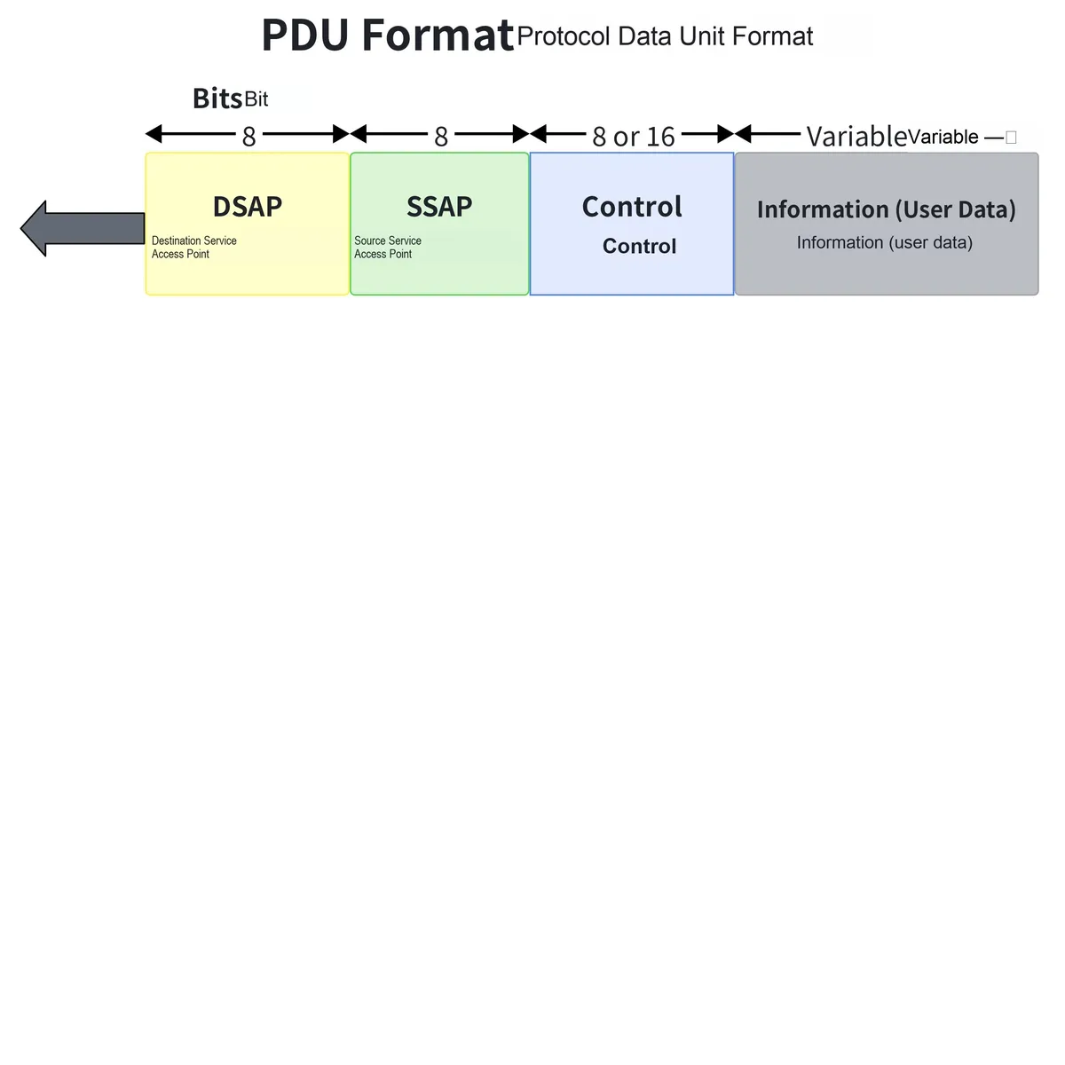
- DSAP (Destination Service Access Point): Destination Service Access Point address, used to indicate the destination protocol of the data packet
- SSAP (Source Service Access Point): Source Service Access Point address, which is used to indicate the source protocol of the data packet
- Control Field: A control field that defines the type and control information of the data packet. For example, the data packet types supported by the LLC layer include information (I-frame), acknowledgment (S-frame), and unnumbered (U-frame), etc.
- information field: carries the actual data payload
1.1.6 DHCP Dynamic Host Configuration Protocol
1.1.6.1 Introduction to DHCP Protocol
Earlier, when we discussed the Network Layer of the OSI model, we mentioned that when using TCP/UDP protocols for data transmission, parameters such as IP Address, subnet mask, and default gateway need to be manually configured. As network scales continue to expand, this manual configuration method has become extremely cumbersome and error-prone. Furthermore, most of the addresses we currently use are IPv4 addresses, which are extremely limited in quantity, and manual IP address allocation also tends to cause address waste.
Meanwhile, for mobile devices such as laptops and smartphones, it is necessary to frequently change the IP Address configuration when switching between different network environments; manually modifying IP settings is not only cumbersome but may also cause network connection interruptions.
This gave rise to the DHCP protocol. Short for Dynamic Host Configuration Protocol, DHCP is a network protocol that dynamically assigns IP Addresses. By automatically assigning IP Addresses and other TCP/IP parameters, DHCP can greatly simplify network configuration work and avoid IP Address conflicts (i. e., two devices using the same IP Address) that occur during manual IP Address configuration.
1.1.6.2 Working Principle of DHCP Protocol
In DHCP, there are mainly three roles: DHCP server, DHCP Client and DHCP relay.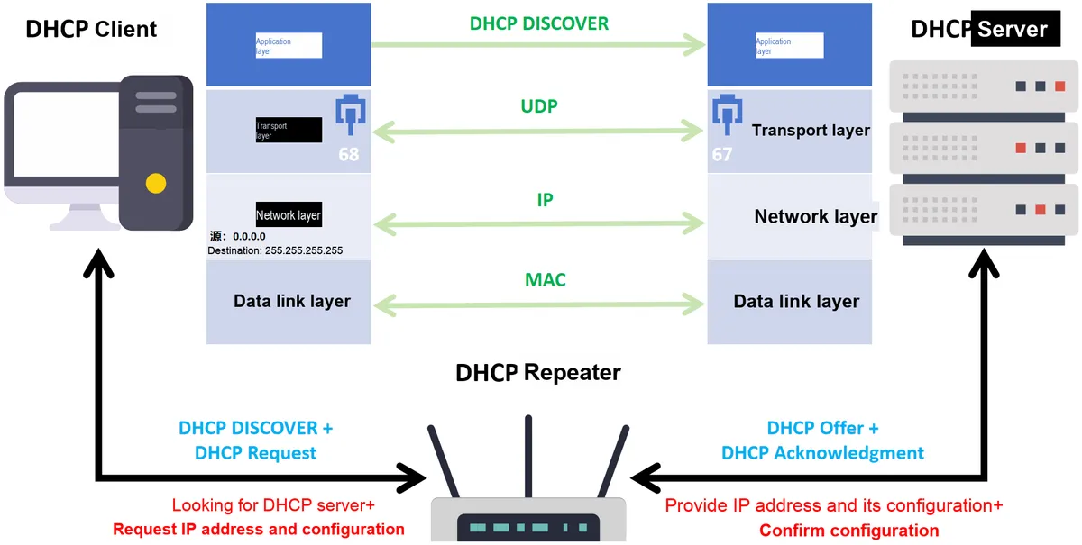
- DHCP Server (DHCP Server)
- IP Address Assignment and Configuration: The DHCP server is responsible for assigning IP Addresses and providing other network configuration parameters (such as subnet mask, default gateway, and DNS servers) to Client devices on the network.
- Address Pool Management: The server maintains an IP Address pool to manage available IP Addresses and their lease periods.
- Respond to requests: When a DHCP Client sends a request, the server responds with the corresponding DHCP message and provides configuration parameters
- DHCP Client (DHCP Client)
- Request Configuration: A DHCP Client is a device on the network (such as a computer, printer, or smartphone) that needs to obtain an IP Address and other network configuration information from a DHCP server
- Auto-configuration: Client uses the DHCP protocol to automatically obtain an IP Address and network configuration without manual setup
- DHCP Relay
- Forwarding Request: A DHCP relay is an intermediate device (such as a router or switch) located between the Client and the server. When the Client and the server are not in the same broadcast domain, the relay is responsible for forwarding the Client's request to the server and forwarding the server's response back to the Client.
- Supports cross-broadcast domain: DHCP relay enables DHCP services to span different network segments or subnets, allowing Client and servers to operate in separate networks
1.1.6.2 Working Steps of the DHCP Protocol
DHCP operates based on UDP, and the steps on its communication link are as follows:
- The DHCP Client broadcasts a DHCP DISCOVER message carrying a transaction ID and the MAC address of the DHCP Client. The source IP Address of the IP datagram encapsulating this message is 0.0.0.0, which is used as a substitute since the host has not been assigned an IP Address yet, and the destination IP Address is the broadcast address 255.255.255.255. The reason for sending it via broadcast is that the host does not yet know which DHCP servers exist on the network.
- When receiving a DHCP Discover message, the server broadcasts a DHCP Offer message, which contains an available IP Address and other configuration parameters
- Client selects an Offer and sends a DHCP Request message to request this IP Address
- The server confirms and sends a DHCP Acknowledgment message to complete the IP Address assignment
- So far, the DHCP network configuration is completed, and then TCP/IP communication can be carried out between the hosts on the communication link.
- When there is no need for an IP Address, the Client can send a DHCPRELEASE packet to release the IP address; in addition, a lease duration is usually configured in DHCP settings, within which the DHCP Client can send a DHCP request packet to notify that it intends to extend this lease period
1.1.7 DNS Protocol
1.1.7.1 Introduction to DNS Protocol
DNS (Domain Name System) is a critical service on the Internet that implements the mapping between domain names and IP Addresses, forming a distributed database. This service enables users to access the Internet more conveniently without having to memorize the numeric IP Addresses that machines can read directly. On the Internet, every computer is assigned a unique identifier, which is the IP Address. However, IP Addresses consist of numbers and are not easy for people to remember.Therefore, we usually use domain names to access various websites; for example, the domain name www.st.com.cn can be used to access the official website of STMicroelectronics.
1.1.7.2 Working Process of DNS Protocol
The workflow of DNS is as follows: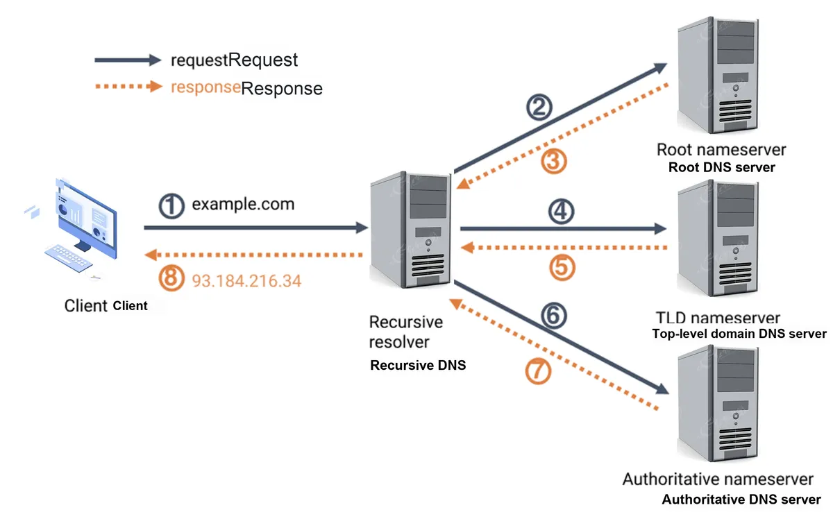
- User device initiates a query: the user enters
www.example.comin the browser and presses Enter, then the browser will send a DNS query request to the local DNS resolver (usually provided by the ISP), requesting thewww.example.comIP Address - Local DNS resolver query: The local DNS resolver checks its cache to see if the IP Address of
www.example.comis already cached. If not, it initiates a recursion query. - Recursion query process:
- Root DNS Server:
- The local DNS resolver first sends a request to the root DNS server. The root DNS server does not directly provide the
www.example.comIP Address, but it knows the address of the DNS server responsible for the. comTop-Level Domain - The root DNS server returns
the address of the. comTop-Level Domain DNS server
- The local DNS resolver first sends a request to the root DNS server. The root DNS server does not directly provide the
- Top-Level Domain DNS server:
- The local DNS resolver then sends a request to the
. comTop-Level Domain DNS server. The Top-Level Domain DNS server knows the address of the authoritative DNS server forexample.com - The Top-Level Domain DNS server returns
example.comthe address of the authoritative DNS server
- The local DNS resolver then sends a request to the
- Authoritative DNS server:
- The local DNS resolver ultimately sends a request to the authoritative DNS server for
example.com. The authoritative DNS server holds the actual DNS records forwww.example.com. - The authoritative DNS server returns
www.example.com's IP Address, for example93.184.216.34
- The local DNS resolver ultimately sends a request to the authoritative DNS server for
- Root DNS Server:
- Caching and Responses: The local DNS resolver caches the
www.example.comIP Address for a certain period of time, so that future requests for the same domain name can be responded to faster, and the local DNS resolver returns the IP Address93.184.216.34to the user's device - User device accesses a website: The user's browser now has
www.example.com's IP Address93.184.216.34, and it uses this IP Address to send an HTTP request to the target server to load the website content
There are many common DNS (Domain Name System) servers:
- 114DNS IPv4: 114.114.114.114 and 114.114.115.115
- Alibaba DNS IPv4: 223.5.5.5 and 223.6.6.6
- Google Public DNS IPv4: 8.8.8.8 and 8.8.4.4
1.1.8 HTTP Protocol
1.1.8.1 Working Principle and Message Structure of HTTP Protocol
HTTP (Hypertext Transfer Protocol) is a protocol used for transmitting and receiving hypertext (such as web pages) over the Internet. It is an application layer protocol that operates at the application layer of the TCP/IP protocol stack. The HTTP protocol defines the communication mode between a Client (usually a browser) and a server, and supports data exchange in the form of requests and responses: the Client sends an HTTP request message to the server, the server processes the received HTTP request message, and then returns a response to the Client.
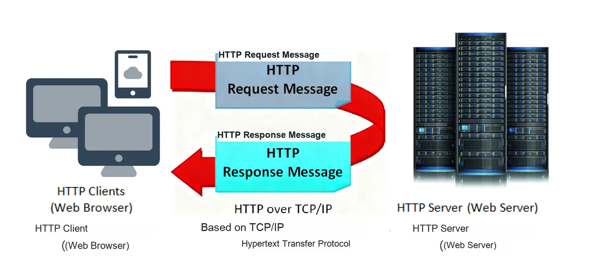
The structures of HTTP request message and response message are as follows:
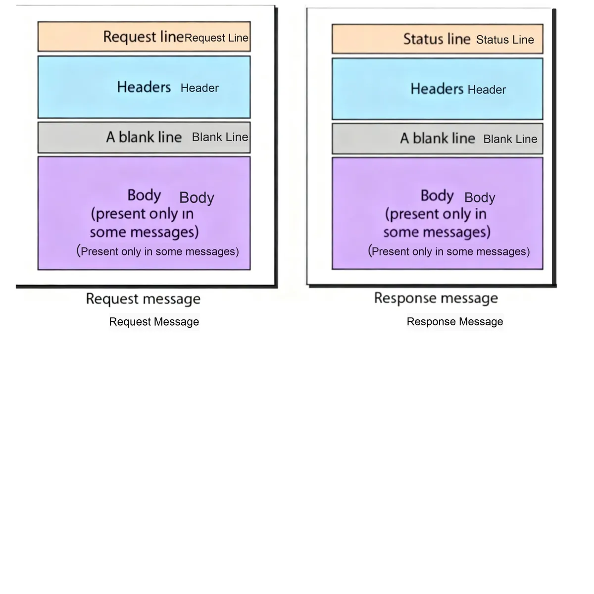
1.1.8.2 HTTP Request Message
An HTTP request message is the data format used when a Client (such as a browser) sends a request to a server, and it consists of a request line, request headers, and an optional request body:
- Request Line: consists of three parts
- Method: Specifies the operation type of the request, for example
GET,POST,PUT,DELETE - Request Target (Request-URI): Specifies the path or URL of the resource to be accessed. URL, Uniform Resource Identifier, is the string used in HTTP requests to designate the requested resource. A URI can be either absolute or relative.
- HTTP Version: Specifies the version of the HTTP protocol to be used, e. g.
HTTP/1.1
- Method: Specifies the operation type of the request, for example
- Request Headers: Request headers contain additional information about the request and the Client. Each request header consists of a header field name and a header field value, in the following format:
<Header-Name>: <Header-Value>. Common request headers include:- Host: Specifies the host name and Port Number of the server (e. g.
Host:www.example.com) - User-Agent: Specifies the Client software information that initiates the request (e. g.
User-Agent: Mozilla/5.0) - Accept: Specifies the media types that the Client can process (e. g.
Accept: text/html) - Accept-Language: Specifies the language accepted by the Client (e. g.
Accept-Language: en-US)
- Host: Specifies the host name and Port Number of the server (e. g.
- Request Body: The request body is used to transmit data in certain HTTP methods (such as
POST,PUT). It is optional and is usually empty forGETrequests. The content format of the request body is specified by theContent-Typerequest header
Common HTTP request methods include:
- GET: Requests a specified resource, typically used to retrieve data, with an empty request body
- POST: Submit data to the specified resource, usually used for submitting forms or uploading files, with the request body containing the data
- PUT: Update the specified resource or create a new resource, with the request body containing data
- DELETE: Delete the specified resource
- HEAD: Similar to
GET, but only requests the response header without returning the response body - OPTIONS : Retrieve the HTTP methods supported by the server
URL (Uniform Resource Locator)
URL (Uniform Resource Locator) is the abbreviation of Uniform Resource Locator, which is the standard form of resource address on the Internet. URL is a specific implementation of URI (Uniform Resource Identifier).
The basic format of a URL is as follows: scheme://host: port/path? query#fragment
where:
- scheme (protocol): indicates the access protocol for a resource, usually
http://orhttps:// - host (host): indicates the host name or IP address where the resource is located
- port (port): indicates the Port Number on the host; it can be omitted if the default port is used (80 for HTTP, 443 for HTTPS)
- path: indicates the specific location or path of a resource on the host
- query (query string): denotes the parameters to be passed to the resource, separated by
?, and multiple parameters are separated by& - fragment (anchor): refers to a specific location or part within a resource, starting with
#
A URL is a standardized form of resource address that provides a uniform way to access resources on the Internet. Through URLs, we can uniquely identify and access various resources on the Internet, such as web pages, images, videos, and files.
1.1.8.3 HTTP Response Message
An HTTP response message is the data format used when a server returns the result of a request to a Client. It consists of three parts: a status line, response headers, and a response body:
- Status Line: consists of three parts
- HTTP Version: Specifies the version of the HTTP protocol to be used, e. g.
HTTP/1.1 - Status Code: A three-digit code that indicates the server's processing result for a request (e. g.,
200,404) - Reason Phrase: A brief description of the status code (e. g.,
OK,Not Found)
- HTTP Version: Specifies the version of the HTTP protocol to be used, e. g.
- Response Headers: Response headers contain additional information returned by the server, such as resource type, server type, content length, cache control, etc. Response headers are also represented in the form of Attribute–Value Pairs:
<Header-Name>: <Header-Value> - Response Body: The response body contains the data content returned by the server to the Client, the content of which is specified by the
Content-Typeresponse header, and the length of which is specified by theContent-Lengthresponse header; the content of the response body can be an HTML page, JSON data, an image, etc.
HTTP status codes are commonly classified into the following types:
- 1xx (Informational): Informational status code, indicating that the request has been received and is being processed. Example:
100 Continue - 2xx (Success): The request has been processed successfully. Example:
200 OK(request succeeded),201 Created(resource created successfully) - 3xx (Redirection): Further action is required to complete the request. Examples:
301 Moved Permanently(the resource has been permanently moved),302 Found(the resource has been temporarily moved) - 4xx (Client Error): The Client request is incorrect. Examples:
400 Bad Request(invalid request),404 Not Found(resource not found) - 5xx (Server Error): The server failed to fulfill a valid request. Examples:
500 Internal Server Error(internal server error),502 Bad Gateway(invalid gateway)
1.1.8.4 Features and Versions of HTTP Protocol
The HTTP protocol supports Cookies, which are small pieces of data stored on the Client and used by servers to track user sessions and personalize settings.
The HTTP protocol itself does not provide encryption, so the data transmitted may be eavesdropped or tampered with. To improve security, HTTPS can be used, which provides data encryption based on HTTP via the SSL/TLS protocol.
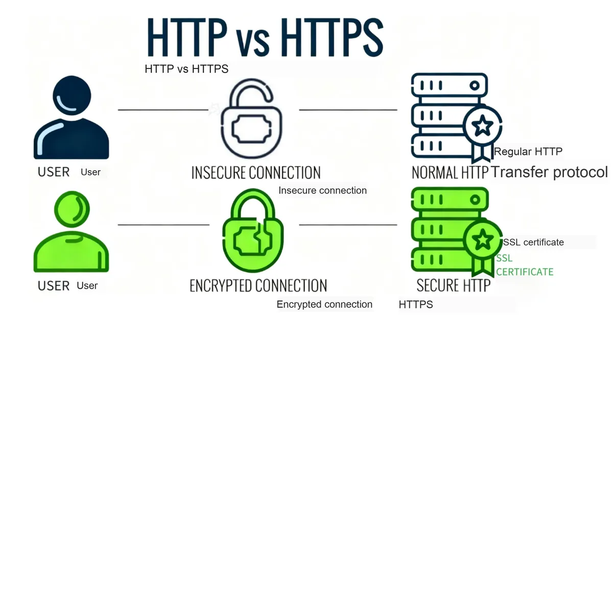
With the development of the Internet, the HTTP protocol has evolved continuously, and its mainstream version is HTTP/2, which introduces features such as multiplexing and header compression on the basis of HTTP/1.1, further improving the speed and performance of web page loading:
- HTTP/1.0: The earliest version of HTTP, which supports basic requests and responses, but requires a separate connection for each request and response.
- HTTP/1.1: introduced improvements such as persistent connections (i. e., connection reuse) and support for pipelining (i. e., sending multiple requests over a single connection), which reduced the overhead of establishing and closing connections.
- HTTP/2: It introduces features such as binary framing, multiplexing and header compression, aiming to improve performance and efficiency.
- HTTP/3: Based on the QUIC protocol, it improves the connection establishment speed and the reliability of data transmission
1.1.8.5 HTML Markup Language
HTML (HyperText Markup Language) is a markup language used to create and design web pages. It defines the structure and content of web pages, and uses tags (such as <div>, <h1>, <p>, etc.) to describe the position and style of text, images, links and other multimedia elements on a page.When you enter a URL in your browser (for example, www.example.com ), the browser sends a request to the server via HTTP, the server returns a response containing HTML content, and the browser then parses the HTML and renders the web page for the user.
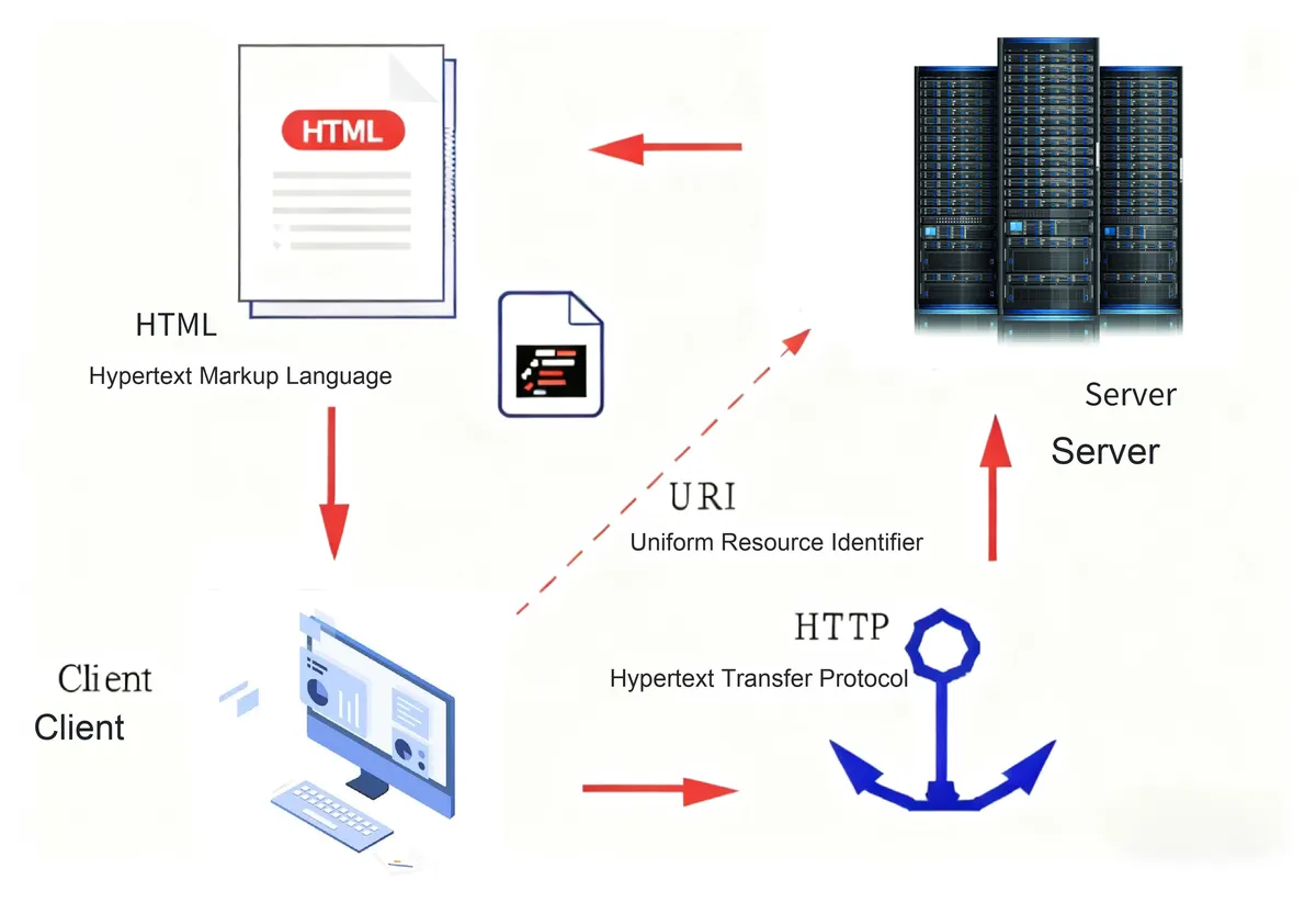
Simply put, HTML is responsible for defining the content and structure of web pages, while HTTP handles the transmission of such content between the Client and the server.
A standard HTML document structure consists of the following parts:
<!DOCTYPE html> <!-- Document type declaration -->
<html lang="en"> <!-- HTML document -->
  <head> <!-- Head -->
    <meta charset="UTF-8"> <!-- Character set -->
    <meta name="viewport" content="width=device-width, initial-scale=1.0"> <!-- Responsive design -->
    <title>Document Title</title> <!-- Page title -->
  </head>
  <body> <!-- Main content -->
    <!-- Content goes here -->
  </body>
</html>
These include several basic tags:
<!DOCTYPE html>: Declares the HTML5 document type to help browsers render web pages<html>: The root element that contains the entire HTML document<head>: Document header, containing information about the document (such as title, metadata, links to CSS files, etc.)<body>: The main body of the document, which contains the actual web page content
Commonly used tags include heading tags, paragraph and text formatting, links and images, lists, tables, forms, etc. :
- Title Tag
<h1>Heading 1</h1>
<h2>Heading 2</h2>
<h3>Heading 3</h3>
<h4>Heading 4</h4>
<h5>Heading 5</h5>
<h6>Heading 6</h6>- Paragraph and Text Formatting
<p>This is a paragraph.</p>
<b>Bold text</b>
<i>Italic text</i>
<strong>Important text</strong>
<em>Emphasized text</em>- Links and Images
<a href="https://www.example.com">Click here to visit Example.com</a>
<img src="image.jpg" alt="描述文字">- List
<!-- Unordered list -->
<ul>
  <li>Item 1</li>
  <li>Item 2</li>
  <li>Item 3</li>
</ul>

<!-- Ordered list -->
<ol>
  <li>First item</li>
  <li>Second item</li>
  <li>Third item</li>
</ol>- Table
<table>
  <thead>
    <tr>
      <th>Header 1</th>
      <th>Header 2</th>
    </tr>
  </thead>
  <tbody>
    <tr>
      <td>Cell 1</td>
      <td>Cell 2</td>
    </tr>
    <tr>
      <td>Cell 3</td>
      <td>Cell 4</td>
    </tr>
  </tbody>
</table>- Form
<form action="/submit" method="post">
  <label for="name">Name:</label>
  <input type="text" id="name" name="name">
  <label for="email">Email:</label>
  <input type="email" id="email" name="email">
  <input type="submit" value="提交">
</form>
HTML elements can have attributes, which provide additional metadata or control how the elements are displayed. Common attributes include:
id: Uniquely identifies the element.
class: Defines the class name of the element, used for CSS styling or JavaScript operations.
style: Inline style definition.
href: The target URL of the link.
src: The source URL of the image.
alt: Alternative text for the image.
For code in HTML, we can add comments to it in the following form:
<!-- This is a comment -->In HTML, we can use various controls to enhance the interactivity and user experience of web pages, such as text input controls, multi-line text input controls, button controls, selection controls, file upload controls, range selection controls, etc. :
- Input Box (Input): Used to receive user input, including text input, numeric input, password input, etc.
<input type="text" placeholder="Enter your name">- Drop-down List (Select): Provides users with a drop-down selection option
<select>
  <option value="option1">Option 1</option>
  <option value="option2">Option 2</option>
  <option value="option3">Option 3</option>
</select>- Checkbox: Allows users to select one or more options
<input type="checkbox" name="option1" value="option1"> Option 1<br>
<input type="checkbox" name="option2" value="option2"> Option 2<br>
<input type="checkbox" name="option3" value="option3"> Option 3- Radio Button (Radio): Allows users to select one option from multiple choices
<input type="radio" name="gender" value="male"> Male<br>
<input type="radio" name="gender" value="female"> Female- Button: Used to trigger specific actions, such as form submission, click events, etc.
<button type="button" onclick="alert('Hello, World!')">Click me</button>- File Upload (File): Allows users to upload files to the server
<input type="file" name="file_upload">- Date Picker (Date): Provides users with the function of selecting dates
<input type="date" name="user_date">- Slider (Range): Allows users to select a value within a specified range
<input type="range" name="volume" min="0" max="100">In practical applications, in addition to common form controls and basic UI components, the combination of HTML, CSS and JavaScript can also implement many complex and custom controls, for example:
- Progress Bar (
<progress>tag) - Rating Widget (usually with custom CSS and JavaScript)
- Pop-up/Dialog Box (using modal boxes or JavaScript libraries)
These controls can have their basic functions defined via HTML structure, be styled for better appearance via CSS, and have interactive behaviors added via JavaScript. For example, you can use CSS animations to enhance the visual effect of the Progress Bar, or use JavaScript to create a dynamic rating system.
1.1.9 MQTT Protocol
1.1.9.1 Introduction to MQTT Protocol
MQTT (Message Queuing Telemetry Transport) is a lightweight messaging protocol based on the publish/subscribe pattern, designed for network environments with low bandwidth, high latency or instability — the "MQ" in its name stands for Message Queue, which originates from IBM's MQSeries message queue product line, although MQTT contains "MQ" in its name, it does not actually require the implementation of queuing functionality.Unlike TCP or UDP protocols that adopt the traditional Client-Server architecture where a Client can communicate with the server, this protocol is based on the publish/subscribe model: the publisher sends messages to the Middleware broker, and the Middleware broker forwards the messages to the corresponding subscribers according to the subscription information of the subscribers. This protocol is particularly suitable for Internet of Things (IoT) applications, as it can effectively reduce network traffic and communication overhead.
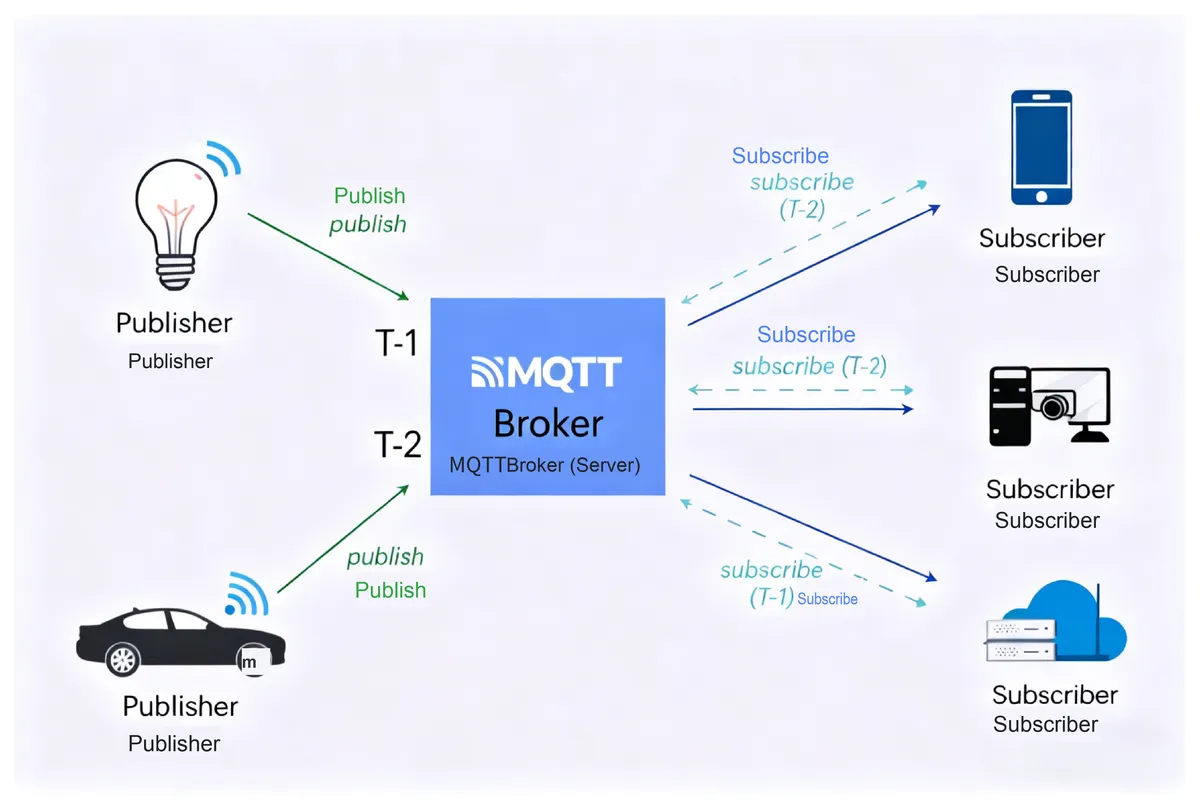
In 1999, Andy Stanford-Clark and Arlen Nipper faced a challenge: they needed to design an efficient communication protocol for an oil pipeline monitoring system connected via satellite. This system was required to operate under extreme environmental conditions, including:
- Bandwidth limitation: Satellite communication bandwidth is usually very limited and costly.
- Battery Consumption: Devices are usually powered by batteries, so it is very important to reduce energy consumption.
- Unreliable network: Satellite connections may suffer from high latency and instability issues.

To address these challenges, the design objectives of the MQTT protocol include:
- Easy to implement: Design a simple protocol that can be implemented on resource-constrained devices to reduce the complexity of development and deployment.
- Reduce data transmission costs: Minimize the overhead of message headers and streamline communication processes to cut down bandwidth usage and data transmission expenses
- Quality of Service (QoS) management: provides message service quality at different levels to meet the requirements of different applications for reliability and efficiency, which enables MQTT to maintain the reliability of message delivery under varying network conditions.
- Continuous Session Control: Allows the Client to maintain a persistent session and continue receiving undelivered messages even when the connection is interrupted
- Flexibility of data format: It does not impose rigid requirements on the specific type or format of data, and allows users to flexibly transmit various types of data as needed
The design of the MQTT protocol successfully addresses these challenges, making it a pivotal protocol for Internet of Things (IoT) and remote monitoring applications. It enables efficient data transmission in environments with limited bandwidth and unstable networks, and is particularly suited for use cases involving embedded devices and remote sensors. In 2013, IBM submitted the specification for MQTT version 3.1 to OASIS to promote its adoption as an open standard. Subsequently, MQTT gradually evolved into one of the standard protocols in the IoT domain.The core principles of the MQTT protocol are as follows: featuring a streamlined design, adopting the publish/subscribe pattern, prioritizing transmission efficiency and reliability in low-bandwidth and high-latency network environments, supporting flexible topic creation and quality of service management, and being suitable for devices with limited computing power.
The main features of the MQTT protocol include:
- Publish-Subscribe Pattern: MQTT adopts the publish-subscribe communication mode, where publishers publish messages to topics, and subscribers subscribe to topics of interest to receive relevant messages. The MQTT protocol requires a Broker as Middleware to manage message publishing and subscription, ensuring that messages can be reliably distributed to subscribers.
- This pattern decouples senders and receivers, enhancing the flexibility and scalability of the system:
- The sender and the receiver achieve spatial decoupling: The publisher does not know which subscribers exist, nor does it need to know. Similarly, subscribers are unaware of which publishers there are, and only need to subscribe to the topics they are interested in.
- The sender and the receiver achieve time decoupling: In the publish-subscribe pattern, publishers and subscribers do not need to be online simultaneously. A publisher can publish messages even when subscribers are not running; the messages will be cached by the Broker and pushed only after the subscribers come online. Likewise, a subscriber can subscribe even when the publisher is offline, and will receive messages immediately once the publisher goes online.
- Meanwhile, publishers and subscribers can send and receive messages asynchronously without waiting for each other's response, thus realizing asynchronous communication.
- This pattern decouples senders and receivers, enhancing the flexibility and scalability of the system:
- Layered Quality of Service (QoS): MQTT provides three distinct levels of message delivery quality of service
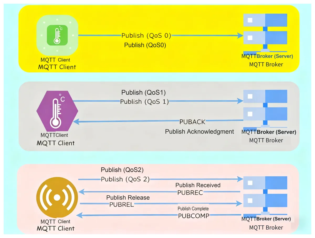
Comparison of Message Delivery Mechanisms for QoS 0, QoS 1 and QoS 2 - QoS 0 (at most once): Messages may be lost, but the transmission overhead is minimized, making it suitable for application scenarios that are insensitive to data loss, such as Data Acquisition of environmental sensor data, where losing a single record will not affect the overall result, or push notifications for ordinary apps — if a smart device is not connected to the internet when a message is pushed, it will not receive the notification.
- QoS 1 (At Least Once): Messages will be delivered at least once, but duplicates may occur, which applies to application scenarios where message arrival needs to be guaranteed and duplicate messages will not cause serious consequences.
- QoS 2 (Exactly Once): The message will be delivered precisely once, which applies to scenarios with extremely strict requirements for message delivery where no message loss or duplication is allowed. For example, billing systems and push notifications for instant messaging apps require guaranteed accurate and error-free message delivery.
By using QoS (Quality of Service) levels, MQTT can control the transmission priority and redundancy of messages, thereby saving bandwidth.
- Lightweight and efficient: The MQTT protocol features a small header that only contains necessary information, reducing communication overhead. Meanwhile, it supports binary encoding to further improve transmission efficiency, making these characteristics well-suited for resource-constrained devices and low-bandwidth network environments.
- Connection Keepalive and Last Will Message: An MQTT Client can configure the keepalive interval, and periodically send connection keepalive messages to the server to ensure the connection remains alive. Meanwhile, the Client can also set a last will message; when the Client disconnects unexpectedly, the server will publish this message to notify other subscribers.
- Topic-based addressing: MQTT uses hierarchical topics to identify messages, and subscribers can subscribe to Wildcard topics to receive multiple related messages; this topic subscription method provides a flexible message routing and filtering mechanism
- Security Mechanism: MQTT supports SSL/TLS encryption to protect the security of message transmission, and it is equipped with dedicated authentication mechanisms such as username/password or OAuth.
- Based on TCP/IP: MQTT operates on top of the TCP/IP protocol stack to ensure reliable data transmission, and there is also a UDP-based version named MQTT-SN
1.1.9.2 MQTT Packet Structure
The basic data unit of MQTT is the message, whose format consists of a Fixed Header, a Variable Header and a Payload:
+----------+-------------------+-------------------+
| Fixed    | Variable Header   | Payload           |
| Header   |                   |                   |
+----------+-------------------+-------------------+
The MQTT message format is as follows:
- Fixed Header:
- Packet Type: Identifies the type of MQTT message, such as connection request (CONNECT), published message (PUBLISH), subscription message (SUBSCRIBE), etc.
- Reserved Bit: Reserved for future expansion
- Packet Quality of Service (QoS Level): specifies the transmission quality level of the message, with valid values being 0 (highest quality), 1 (at-least-once delivery guarantee), or 2 (exactly-once delivery)
- Duplication Flag: Indicates whether this message is a duplicate message
- Keep Alive: Indicates how often the Client should send keep-alive messages to maintain the connection
- Variable Header:
- Protocol Name: Always "MQTT"
- Protocol Level: indicates the MQTT version supported by the Client and the server
- Connection ID: An ID that uniquely identifies a Client connection
- Username: Optional field for identity authentication
- Password: Optional field used for identity authentication
- Heartbeat: Optional field used to check whether the connection is active
- Payload: The payload contains the actual data to be transmitted, and its length depends on the message type and QoS level.
- For PUBLISH messages, the message body contains the Topic and the Message Content.
- For SUBSCRIBE messages, the message body contains the list of subscribed topics (Topic List)
The design of the MQTT packet format aims to ensure message compactness and minimize transmission overhead, which is particularly critical for resource-constrained devices.
The following are common MQTT packet formats:
- CONNECT Packet: Used by the Client to request a connection to the server
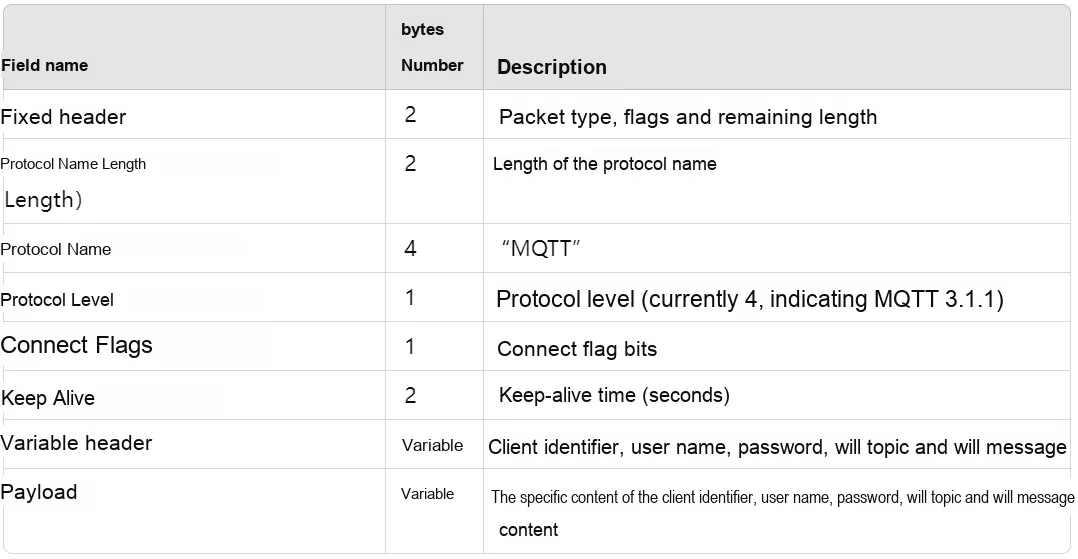
- CONNACK packet: used to acknowledge a connection request
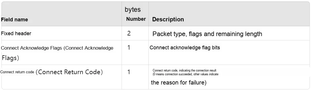
- PUBLISH packet: used for publishing messages
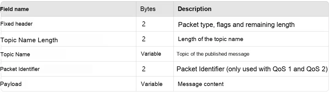
- PUBACK packet: used to confirm the receipt of a PUBLISH packet

- SUBSCRIBE Packet: Used for subscribing to topics
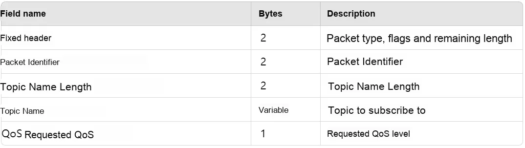
- SUBACK packet: used to confirm a SUBSCRIBE packet

- DISCONNECT message: used to terminate the connection

1.1.9.3 Workflow of MQTT Protocol
The workflow of the MQTT protocol consists of the following four steps: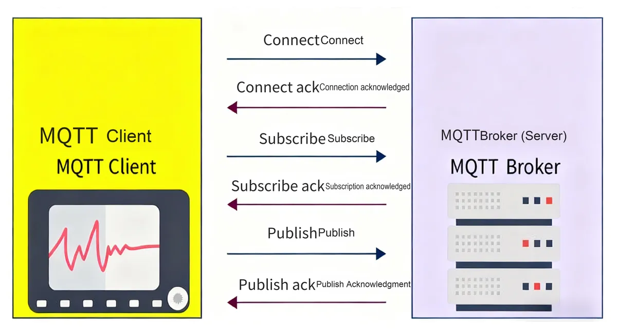
Need to redraw the diagram and supplement the Chinese content
- Client connects to the MQTT server: The Client establishes a connection with the MQTT server via the TCP/IP protocol
- The Client connects to the MQTT broker server, and during the connection process, it is required to provide information such as the client identifier (ClientId), username and password to the server
- Client sends a CONNECT packet, and the broker returns a CONNACK packet to confirm the connection
- If the connection succeeds, a session will be established between the Client and the server, and data transmission will commence.
- Subscribe to Topics: After establishing a connection, the Client can subscribe to topics of interest to receive messages published to those topics
- The Client sends a SUBSCRIBE packet to subscribe to one or more topics, and the packet needs to specify the topics to be subscribed to and the QoS level.
- The server returns a SUBACK packet to confirm the subscription, indicating whether the topic subscription succeeds or fails.
- Message Publishing: After a connection is established, the Client can publish messages to a specified topic
- The Client sends a PUBLISH packet to publish a message to a specified topic, and the topic to be published and the message content need to be specified in the packet.
- The server will return a PUBACK packet to indicate whether the message publication succeeds or fails.
- Disconnection: The Client can actively disconnect from the MQTT server
- The Client sends a DISCONNECT packet to disconnect the connection
- The server will return a DISCONNECT packet, indicating that the connection has been successfully disconnected.
Among these steps, the publishing and subscription steps are not limited to being configured only once, and can be configured multiple times.
It can be seen that the communication roles in the MQTT protocol are as follows:
- Server/Broker:
- Responsible for managing and forwarding messages
- Maintain the connection status of the Client
- Receive messages published by publishers and distribute them to subscribers who have subscribed to the relevant topics
- Client/Client: A client can both publish and subscribe, which is divided into the following two types according to the data direction of communication
- Subscriber: It usually needs to maintain a persistent connection with the broker. This is because the subscriber expects to continuously receive messages on the topics it is interested in, and if the connection with the broker is interrupted, the subscriber may miss messages published to the topics it has subscribed to.
- Connect to the broker and subscribe to the topics you are interested in
- Receive messages only when there are new updates in the thread
- Multiple topics can be subscribed to, and messages from different topics can be processed accordingly.
- Publisher: A connection is usually established only when there is a message to be published. Once the message publication is completed, the publisher can disconnect. This practice helps save resources, especially in scenarios with low publishing frequency; if a publisher needs to publish messages frequently, it may choose to maintain the connection to avoid reconnecting to the broker for each individual publication.
- Connect to the broker and publish messages to a specific topic
- There is no need to maintain a long-term connection; a connection only needs to be established when a message needs to be sent.
- Multiple publishers can publish to the same topic
- Subscriber: It usually needs to maintain a persistent connection with the broker. This is because the subscriber expects to continuously receive messages on the topics it is interested in, and if the connection with the broker is interrupted, the subscriber may miss messages published to the topics it has subscribed to.
1.1.9.4 MQTT Keepalive Mechanism
The MQTT heartbeat mechanism works by periodically sending PINGREQ packets to maintain the connection between the Client and the server. Upon receiving the PINGREQ packet, the server will immediately respond with a PINGRESP packet. This process ensures that the connection between the Client and the server remains active and prevents the connection from being disconnected due to prolonged idling.
In MQTT, the heartbeat mechanism is controlled by the keepalive parameter. This parameter indicates the maximum allowed idle time (in seconds) between the Client and the server. If the Client does not send any messages within the keepalive interval, it will automatically send a PINGREQ packet. If the server does not receive any messages (including PINGREQ packets) from the Client for a period of time, it may disconnect the connection.
1.1.9.5 MQTT Version
The MQTT protocol has undergone several versions of evolution. Below is a brief introduction to its major versions: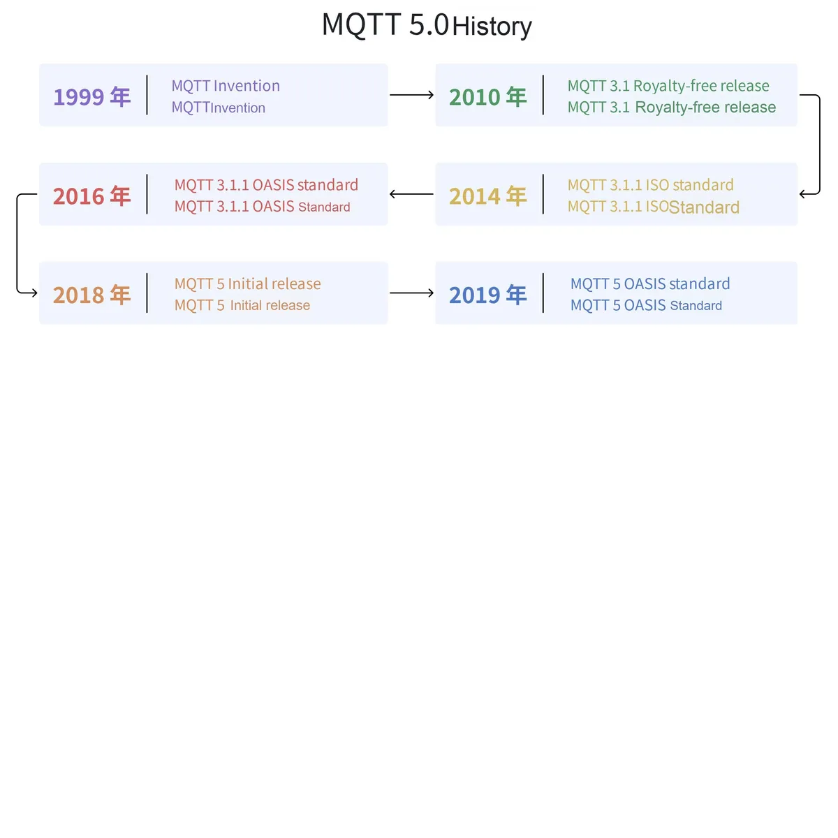
- MQTT 3.1 (2010): Released by IBM, this was the first public version of MQTT, designed to enable device communication in low-bandwidth, high-latency, and unreliable network environments. It introduced basic Quality of Service (QoS) levels, the topic publish-subscribe mechanism, and the Keep Alive mechanism.
- MQTT 3.1.1 (2014): Released by OASIS (Organization for the Advancement of Structured Information Standards) as the official standard for the MQTT protocol. It introduces a number of improvements and corrections based on MQTT 3.1, including clarifying certain detailed requirements of the protocol, and enhancing aspects such as connection mechanisms, message formats, and error handling.
- MQTT 5.0 (2019): Released by OASIS, it introduces numerous new features and improvements, including enhanced error reporting, message properties, user properties, request/response pattern, topic aliases, etc. It supports more complex message delivery modes and extends the QoS (Quality of Service) management capabilities.
1.1.10 Modbus TCP Protocol
1.1.10.1 Introduction to Modbus TCP Protocol
Modbus TCP is a TCP/IP-based implementation of the Modbus protocol, used for transmitting Modbus protocol data over Ethernet networks. Modbus adopts a master-slave architecture, in which one device acts as the master station and the other devices serve as slave stations. The master station sends requests, and the slave stations respond to the requests and send data. This communication mode allows one master station to communicate with multiple slave stations simultaneously, thereby enabling centralized management and control.
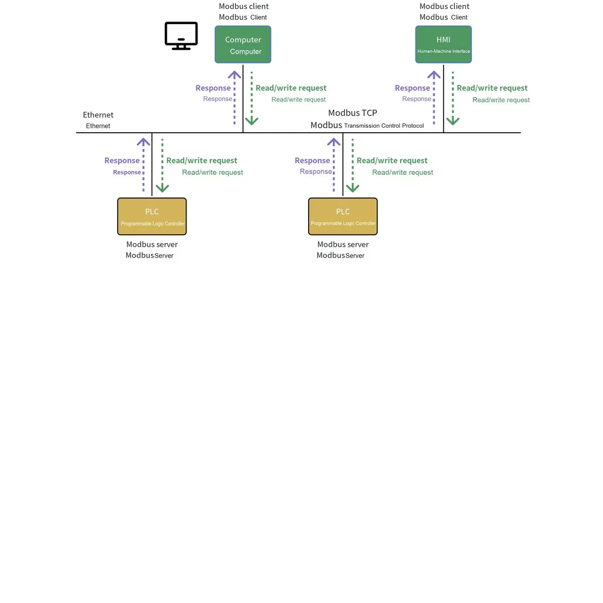
The main features of the Modbus TCP protocol include:
- TCP/IP-based communication: Modbus TCP adopts the standard TCP/IP protocol stack as the underlying transport layer, enabling communication over Ethernet networks. This endows Modbus TCP with excellent network compatibility and a wide range of application scenarios.
- Client-Server Architecture: Modbus TCP adopts the classic Client-Server mode. A Client (usually a device such as a PLC or HMI) sends a Modbus request, and the server (usually a Modbus slave device) responds and returns data.
- Modbus Service Function Codes: Modbus TCP inherits the function codes of the Modbus protocol, covering common functions such as reading/writing single/multiple registers and reading/writing single/multiple coils, which ensures the compatibility between Modbus TCP and existing Modbus applications.
- Message Format: A Modbus TCP message consists of the Modbus Application Protocol Data Unit (MBAP) and Modbus function codes/data. The MBAP header contains fields such as the transaction identifier, protocol identifier, length, and unit identifier, which are used to identify the message.
- Port Number: Modbus TCP uses port number 502 by default, which is the standard port for the Modbus protocol over TCP/IP
- Connection Management: A Modbus TCP Client usually initiates a TCP connection to the server proactively, and this connection can be reused for multiple Modbus requests. The server side is responsible for processing and responding to requests from the Client.
- Performance: Compared with the traditional Modbus RTU (serial) protocol, Modbus TCP delivers better performance in terms of network latency, throughput and other aspects, but it also needs to handle the overhead brought by the TCP/IP protocol stack.
In industrial automation control systems, the Modbus TCP protocol is a commonly used data exchange protocol that enables different control systems to communicate over TCP/IP networks. There are several key reasons why this protocol is so important in industrial automation:
- Data exchange between devices: The Modbus TCP protocol enables data exchange between different devices, including sensors, actuators and other industrial automation components. This capability is critical for integrated and automated control systems.
- Remote Access and Control: Since Modbus TCP is based on TCP/IP, it supports remote access and control over the Internet, which means operators can monitor and control industrial equipment from any location, thus improving work flexibility.
- Integration with Other Communication Protocols: The openness of Modbus TCP enables it to be integrated with other Communication Protocols such as HTTP, FTP or MQTT. This flexibility allows Modbus TCP to be applied in diverse system and device environments.
- Real-time Data Communication: For applications requiring real-time monitoring and control, Modbus TCP is capable of providing real-time data communication. In fields such as energy management and environmental monitoring, real-time data communication is the key to achieving accurate and timely control.
1.1.10.2 Modbus TCP Data Frame
The data frames of Modbus TCP can be divided into two parts: MBAP and PDU, as specified below: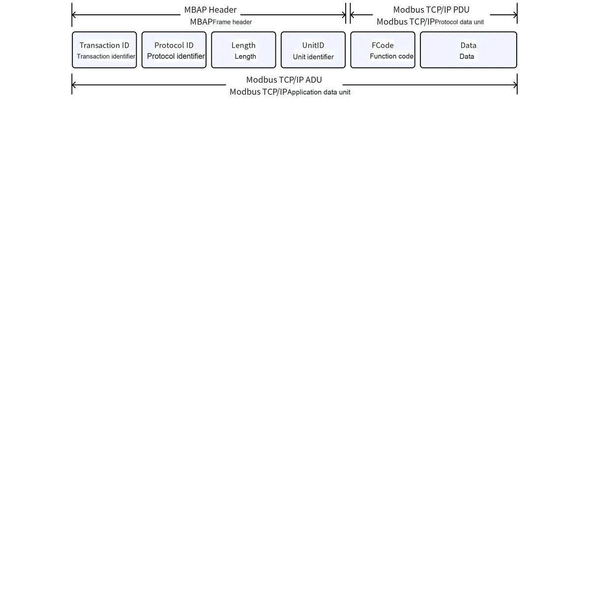
- MBAP (Modbus Application Protocol): The message header, whose function is to locate Modbus requests or responses in a TCP/IP network and ensure that correct data is transmitted to the target device, has a fixed length of 7 bytes.
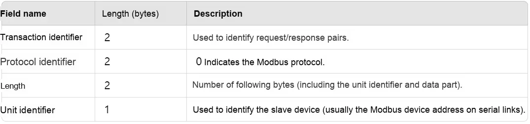
- PDU (Protocol Data Unit): It is the core part of the Modbus protocol and contains the specific data to be transmitted. The PDU consists of two parts:

- Function Code: A function code is 1 byte long, which defines the type of data in the PDU or the operation to be performed, such as reading from or writing to registers.
- Data: The length of the data part is variable, depending on the specific function to be performed
1.1.10.3 Modbus TCP Data Frame Function Code
The function codes of Modbus TCP data frames are used to specify the operation to be performed. Listed below are some common function codes and their descriptions:
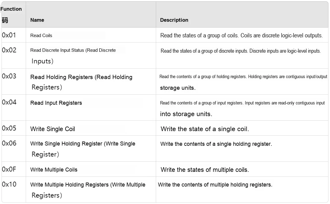
According to specific Modbus application requirements, master devices (such as PLCs and HMIs) send corresponding function code requests to slave devices, which perform corresponding operations based on the function codes and return response data. These function codes provide Modbus TCP with rich data access and control capabilities.
1.1.11 PPP Protocol and PPPoE Protocol
PPP (Point-to-Point Protocol) is a data link layer Communication Protocol that is widely used to transmit packets of various network layer protocols between two directly connected nodes. It is most commonly used for dial-up Internet access, but can also be applied to other types of point-to-point communications, such as serial connections, ISDN, and certain types of broadband access.
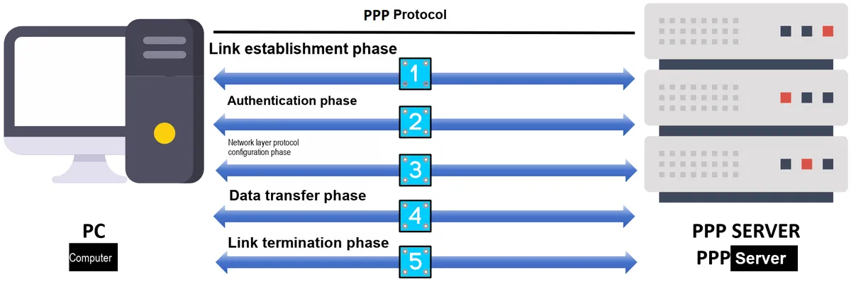
Its main features are as follows:
- Link Control Protocol (LCP):
- used to establish, configure and test data link connections
- It supports link quality monitoring, error detection, and multiple link configuration options.
- LCP negotiates various link parameters, such as the maximum frame length and authentication protocols.
- Network Control Protocol (NCP):
- It is used to configure and manage different network layer protocol data for each network layer protocol
- Common NCPs include the IP Control Protocol (IPCP), the IPv6 Control Protocol (IPV6CP), etc.
- Authentication Mechanism:
- PPP supports multiple authentication protocols, such as PAP (Password Authentication Protocol) and CHAP (Challenge Handshake Authentication Protocol).
- Authentication mechanisms are used to verify the identities of both parties involved in a connection to ensure the security of the connection.
- Multi-protocol Support:
- PPP can encapsulate and transmit data packets of multiple network layer protocols, including IP, IPX, AppleTalk, etc.
- Segmentation and Reassembly:
- It supports splitting Big data packets into smaller frames for transmission and reassembling them at the receiving end
The workflow is as follows:
- Link Establishment Phase:
- Establish a physical link using the LCP packet, and both parties negotiate link parameters
- After confirming that the link is normal, proceed to the authentication phase (if required)
- Certification Phase (Optional):
- Authenticate using PAP or CHAP to verify the identity of the peer
- After successful authentication, the process proceeds to the network layer protocol configuration phase.
- Network Layer Protocol Configuration Phase:
- Configure network layer protocol parameters using NCP, such as IP Address, DNS server, etc.
- Each network layer protocol has a corresponding NCP for specific configuration.
- Data Transmission Phase:
- After the physical link is established and the network layer protocol configuration is completed, data transmission starts.
- Encapsulate network layer data packets using PPP frames and transmit them over physical links
- Link Termination Phase:
- When communication is completed or an error occurs, use LCP packets to terminate the link
- Clean up resources and disconnect the physical connection
The basic structure of a PPP frame is as follows:
| Field | Size | · |
|---|---|---|
| Flag | 1 byte | Flag field, used to indicate the start and end of a frame |
| Address | 1 byte | Broadcast address field, usually 0xFF |
| Control | 1 byte | Control field, usually 0x03 |
| Protocol | 2 bytes | Indicates the type of the encapsulated packet |
| Information | Variable length | Packet payload |
| FCS (Frame Check Sequence) | 2 or 4 bytes | Frame check sequence, used for error detection |
PPPoE (Point-to-Point Protocol over Ethernet) is a technology that encapsulates the PPP protocol on Ethernet links, providing PPP with data link layer transmission based on Ethernet, enabling PPP to communicate over Ethernet networks.
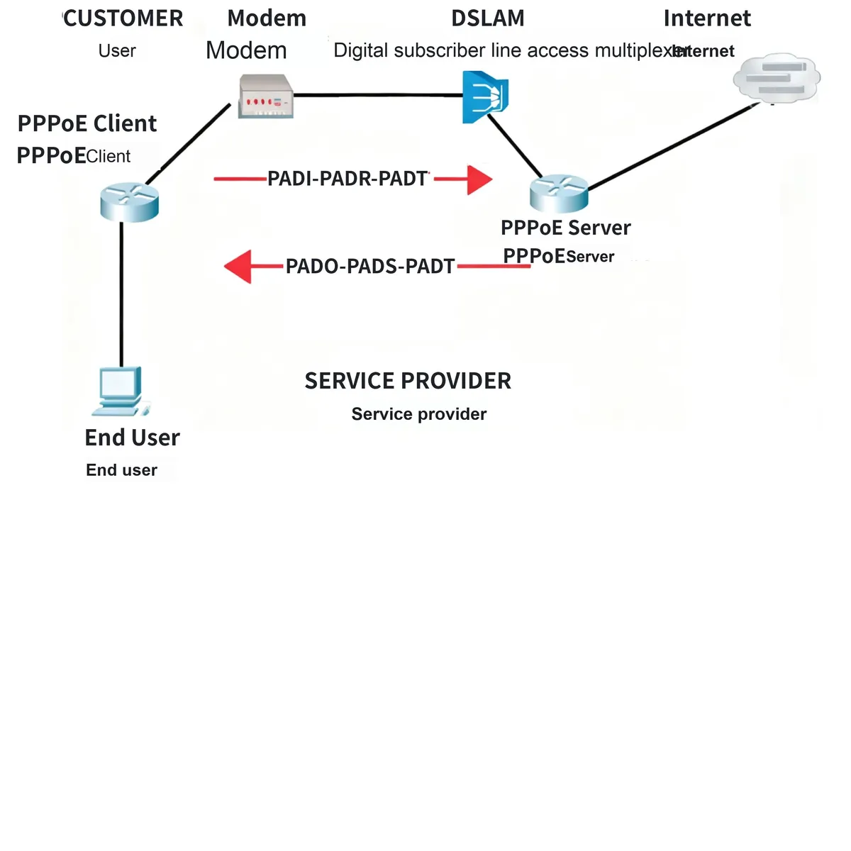
The workflow of the PPPoE protocol is as follows:
- Discovery Phase:
- PPPoE Active Discovery Initiation (PADI): The Client broadcasts PADI packets to search for PPPoE servers
- PPPoE Active Discovery Offer (PADO): The PPPoE server responds with a PADO packet to provide services
- PPPoE Active Discovery Request (PADR): The Client selects a server and sends a PADR packet to request services.
- PPPoE Active Discovery Session-confirmation (PADS): The server sends a PADS packet to confirm the session and assign a session ID.
- Session Phase:
- Use PPP to establish and configure links, including authentication, network layer protocol configuration and data transmission
- PPP frames are encapsulated in Ethernet frames and transmitted over Ethernet.
- Termination Phase:
- Terminate the session and clean up resources by using PPPoE Active Discovery Termination (PADT) packets
1.2 Introduction to the W5500 Ethernet Module
W5500 is a chip produced by WIZnet, which integrates a TCP/IP protocol stack, 10/100M MAC and PHY. This chip can implement network connectivity on a single chip, making it ideal for network applications in embedded systems. The W5500 chip communicates with the host MCU via SPI, featuring a simple interface and high transmission speed. Users can easily write drivers to control the W5500 chip to achieve data reception and transmission.In practical applications, the W5500 can be used in devices that require network connectivity, such as smart home devices and Internet of Things gateways.
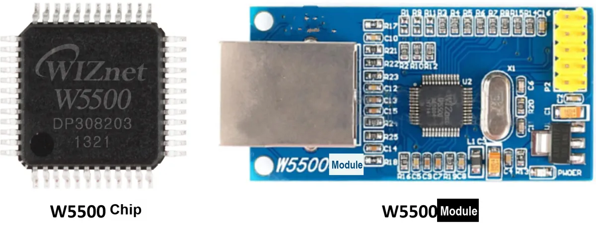
The main features of the W5500 chip are as follows:
- This chip supports the following hardwired TCP/IP protocols: TCP, UDP, ICMP, IPv4, ARP, IGMP, PPPoE
- It supports the simultaneous use of 8 independent sockets, and has 32KB of internal memory for send/receive buffers.
- It supports power-off mode and enables the remote wake-up LAN function via UDP.
- It supports the High-Speed Serial Peripheral Interface (SPI Mode 0 and 3), with a data transmission speed of up to 133 Mbps.
- It has a built-in 10BaseT/100BaseTX Ethernet PHY,
- Supports auto-negotiation (full-duplex and half-duplex, based on 10 and 100), and does not support IP fragmentation
- Operates at 3.3V, features 5V I/O signal tolerance, and comes in a 48-pin LQFP lead-free package (7x7mm, 0.5mm pitch)
- with LED outputs (full-duplex/half-duplex, link, speed, activity)
1.2.1 Internal Structure of the W5500 Chip
The internal structure diagram of the W5500 chip is as follows:
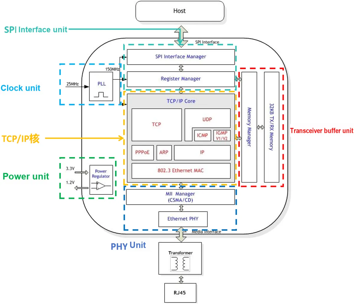
Here, we divide its internal structure into the following parts:
- Clock Unit: It requires a 25MHz clock source for driving, and the frequency is multiplied to 150MHz via a Phase-Locked Loop (PLL) inside the chip.
- Power supply unit: Powered by 3.3V, it can generate a 1.2V power output
- PHY unit: A physical layer (PHY) is internally integrated, which is used for signal conversion and transmission, automatic link detection and cable type detection; the chip adopts the MAC of the 802.3 Ethernet link layer, supports auto-negotiation for 10/100M connection, and controls the PHY through the MII Manager to perform network communication at the link layer.
- TCP/IP Core: A complete TCP/IP protocol stack is built in, supporting protocols such as TCP, UDP, IP, ARP, ICMP and IGMP. It also provides a set of Socket interfaces, supporting up to 8 Sockets; users only need to focus on how to implement UDP and TCP communication through Socket programming.
- Transmit and Receive Buffer Unit: Consists of a transmit buffer and a receive buffer for storing data packets. Users can allocate an appropriate size of transmit and receive buffer for each Socket by modifying the register configuration of the W5500.
- SPI Interface Unit: It provides a communication interface with the main controller, supporting a maximum communication frequency of 80MHz. Users can access the registers of the W5500 through the SPI interface to complete tasks such as device configuration and network communication.
1.2.2 Pins and Peripheral Circuits of the W5500
The W5500 chip features the following pin units:
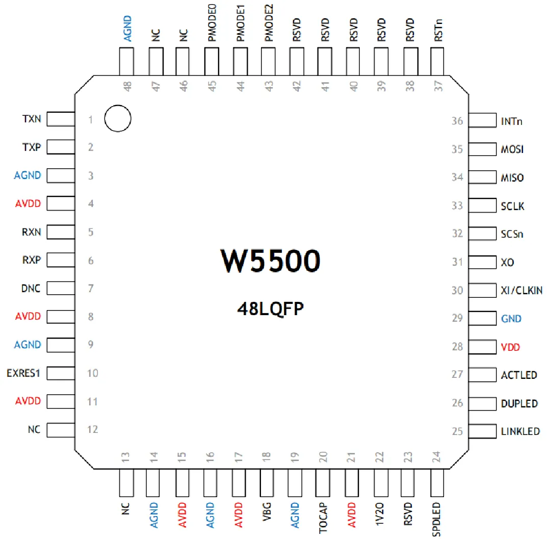
The functions of the pins are as follows:
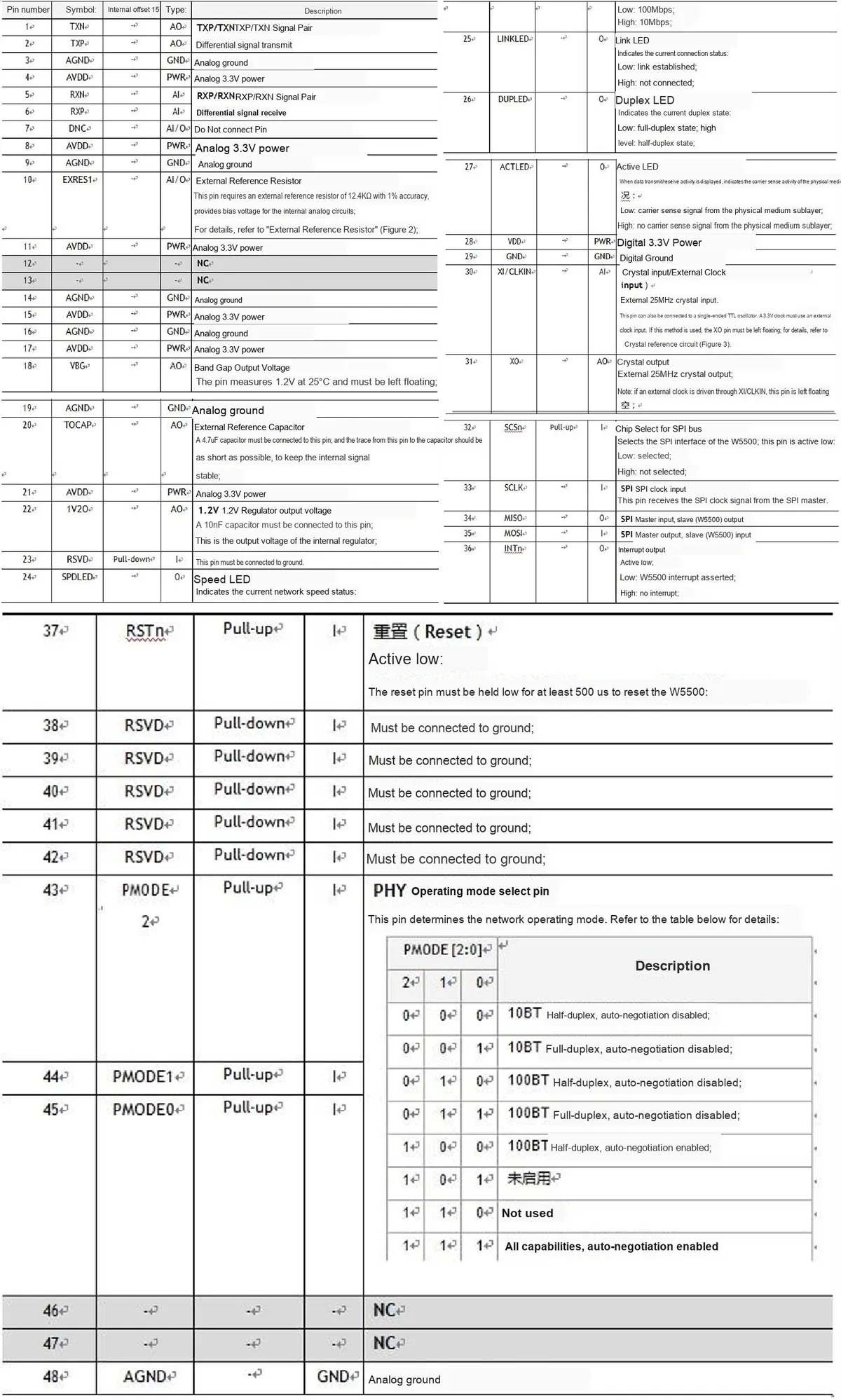
Simply put, pins can be classified as follows:
- Power Supply and Ground
- VCC (3.3V): Supplies 3.3V power
- GND: Ground pin
- AVDD: Analog 3.3V power supply
- AGND: Analog ground pin
- Network Interface Pin
- TXN (1): Differential transmit data negative signal
- TXP (2): Differential transmit data positive signal
- RXN (5): Differential Received Data Negative Signal
- RXP (6): Differential Receive Data Positive Signal
- Reset and Clock
- RSTn (37): Reset signal, active low
- XI/CLKIN (30): External 25MHz crystal oscillator input or external clock input
- XO (31): External 25MHz crystal oscillator output
- SPI interface pins
- SCSn (32): SPI chip select signal, active low
- SCLK (33): SPI clock signal
- MOSI (35): SPI Master Output, Slave Input
- MISO (34): SPI Master In, Slave Out signal
- INTn (36): Interrupt output signal, active low
- Indicator pin
- SPDLED (24): Speed indicator; low level indicates 100Mbps, high level indicates 10Mbps
- LINKLED (25): Link indicator light. A low level indicates that a link is established, while a high level indicates that no link is established.
- DUPLED (26): Full-duplex/half-duplex indicator; a low level indicates full-duplex mode, while a high level indicates half-duplex mode
- ACTLED (27): Activity indicator LED. A low level indicates carrier sense is present, while a high level indicates no carrier sense.
- Other pins
- EXRES1 (10): External reference resistance pin, connect a 12.4KΩ resistor for internal analog circuit biasing
- TOCAP (20): External reference capacitor pin, connect a 4.7uF capacitor
- 1V2O (22): 1.2V regulated output voltage, connect a 10nF capacitor to this pin
- PMODE2 (43), PMODE1 (44), PMODE0 (45): PHY operating mode selection pins
- VBG (18): Bandgap output voltage, floating
- RSVD (23,38,39,40,41,42): Reserved pins, connected to ground
The reference peripheral circuits are as follows:
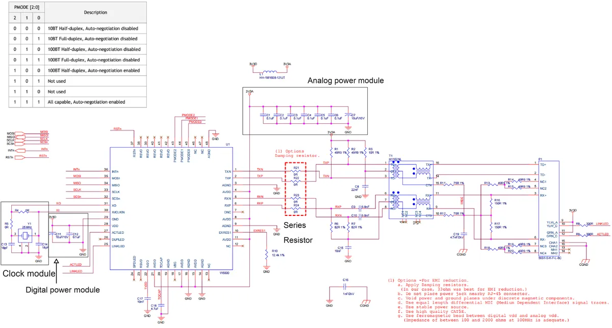
It can be seen that the network interface is connected to the RJ45 jack via a network transformer, which functions to provide isolation and impedance matching, and a damping resistor for suppressing circuit oscillation is connected in series on the network interface.
When using the W5500 chip, we need to connect the following pins of the W5500 chip with a microcontroller:
Pin Name | Pin Description |
VCC | Connect to a 3.3V power supply |
GND | Connect the GND of the microcontroller |
MISO | SPI Master In Slave Out signal, connected to the MISO port of the microcontroller |
MOSI | SPI master output-slave input signal, connected to the MOSI port of the microcontroller |
SCS | Chip select signal, connected to the GPIO port of the microcontroller |
SCLK | SCLK clock signal, connected to the SCLK pin of the microcontroller |
RST | Reset signal, connected to the GPIO port of the microcontroller |
INT | Interrupt output signal, connected to the GPIO port of the microcontroller |
1.2.3 Host Interface and SPI Data Frame Format
The W5500 communicates with the host via SPI slave mode, requiring four signal lines: SCSn, SCLK, MOSI, and MISO.
In SPI, there are a total of 4 operating modes depending on the level and phase of the clock signal SCLK. Among them, both Mode 0 (CPOL = 0, CPHA = 0) and Mode 3 (CPOL = 1, CPHA = 1) sample data on the rising edge of the clock signal and prepare data on the falling edge. The W5500 only supports these two operating modes, and each data transmission is carried out from the Most Significant Bit (MSB) to the Least Significant Bit (LSB).
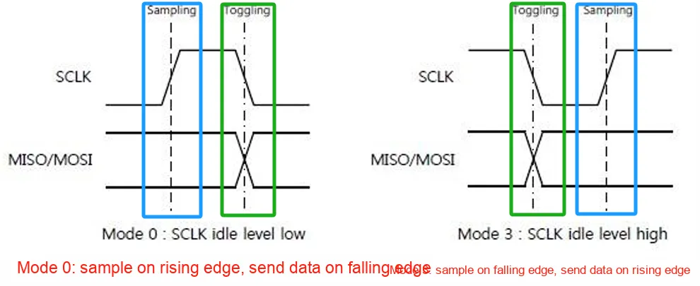
The W5500 supports both fixed-length data communication and variable-length data communication with the host, which is specifically determined by the OM bit (operation mode bit) in the SPI data frame control field of the communication data frame: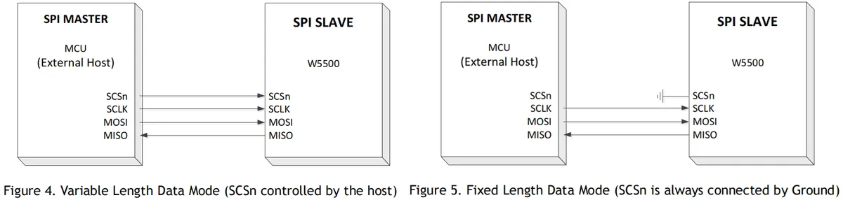
- When OM[1:0] = '01'/'10'/'11', FDM fixed data length communication mode:
- Data is transmitted in fixed-length data blocks, which is typically applied in scenarios where the data length is known and fixed, such as certain real-time control applications.
- The SCSn pin can be directly grounded, in which case the host's SPI port will be exclusively occupied by the W5500 and can no longer be used for communication with other devices.
- When OM[1:0] = '00', VDM variable data length communication mode:
- Data transmission can be performed as required, and the length of data frames can be varied, making it suitable for applications where the data length is uncertain or dynamic adjustment is needed.
- The chip select signal SCSn will be used as the signal to mark the end of data transmission, and in this mode, the SCSn signal line must be controlled by the host:
- When the SCSn signal is pulled low (from high level to low level), it indicates the start of the SPI frame of the W5500.
- When the SCSn signal goes high (from low level to high level), it indicates the end of the SPI frame of the W5500.
The SPI data frame format of the W5500 consists of a 16-bit address field, an 8-bit control field, and N bytes of data field:
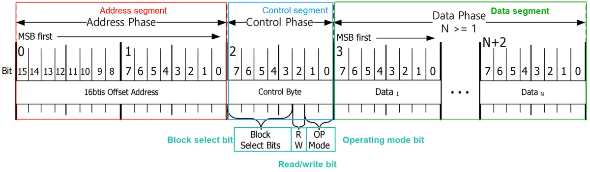
Wherein:
- Address Phase: The address phase describes the offset address for read and write accesses in the data phase. Inside the W5500, continuous read and write access to data is implemented via address auto-increment based on the 16-bit offset address contained in this phase.
- Control Phase:
The control section consists of three parts: the operation mode (OM), the read/write bit (RWB), and the block select bit (BSB).
- OM (Operation Mode): corresponding to the last two bits of the control segment, which is used to describe the length mode of this communication
- 00b: Variable Length Mode
- 01b: Fixed length, the data segment length is 1 byte
- 10b: Fixed length, the data segment length is 2 bytes
- 11b: Fixed length, the data segment length is 4 bytes
- In the variable-length mode, the host-controlled chip select signal changes from a high level to a low level, marking the start of a communication. After the N-byte data segment is completely transmitted, the host sets the chip select signal to a high level, marking the end of the communication.
- In the communication mode with a fixed length, the length of the data segment is selected according to the value in OM. When the W5500 detects that the data segment has transmitted data of the specified length, it considers one communication to be completed.
- In all cases, the chip select signal SCSn must be kept low during the communication process.
- RWB (Read/Write Bit): describes whether the current communication is a read operation or a write operation
- 0: Write operation
- 1: Read operation
- BSB (Block Select Bits, Block Select Bits): Used to select the internal registers or memory space of the W5500
- The W5500 features a general register block that is used to configure the operating modes of the W5500, including the local IP Address, MAC address, subnet mask, gateway, and PHY.
- 8 socket register blocks, which are used for socket programming to implement UDP or TCP communication
- Each Socket has a read buffer and a write buffer for network communication.
- OM (Operation Mode): corresponding to the last two bits of the control segment, which is used to describe the length mode of this communication
- Data Phase: The data phase refers to the actually transmitted data. Its length is determined by the OM bit of the control phase and the chip select signal (SCSn), and the transmission direction of the data is determined by the RWB bit of the control phase.
1.2.4 Register and Memory Organization
1.2.4.1 Overview of W5500 Register and Memory Organization
The W5500 features a general register block, eight socket register blocks, and TX/RX buffer blocks allocated for each socket:
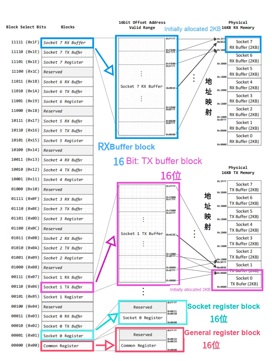
Wherein:
- The TX buffer block of each Socket resides in the physical 16KB TX memory, with an initial allocation of 2KB; the valid address range of the TX buffer is from 0x0000 to 0xFFFF, which is a 16-bit address range.
- The RX buffer block for each Socket also resides in the physical 16KB RX memory, with an initial allocation of 2KB; the valid address range of the RX buffer also spans from 0x0000 to 0xFFFF, which is a 16-bit address range.
Each block is selected by the BSB[4:0](Block Select Bits) of the SPI data frame:
BSB [4:0] | Meaning |
00000 | Select general-purpose registers |
00001 | Select Socket 0 Register |
00010 | Select Socket 0 TX Buffer |
00011 | Select Socket 0 RX Buffer |
00100 | Retain |
00101 | Select Socket 1 Register |
00110 | Select Socket 1 TX Buffer |
00111 | Select Socket 1 RX Buffer |
01000 | Retain |
01001 | Select Socket 2 Register |
01010 | Select Socket 2 TX Buffer |
01011 | Select Socket 2 RX Buffer |
01100 | Retain |
01101 | Select Socket 3 register |
01110 | Select Socket 3 TX Buffer |
01111 | Select Socket 3 RX Buffer |
10000 | Retain |
10001 | Select Socket 4 Register |
10010 | Select Socket 4 TX Buffer |
10011 | Select Socket 4 RX Buffer |
10100 | Retain |
10101 | Select Socket 5 Register |
10110 | Select Socket 5 TX Buffer |
10111 | Select Socket 5 RX Buffer |
11000 | Retain |
11001 | Select Socket 6 register |
11010 | Select Socket 6 TX Buffer |
11011 | Select Socket 6 RX Buffer |
11100 | Retain |
11101 | Select Socket 7 Register |
11110 | Select Socket 7 TX Buffer |
11111 | Select Socket 7 RX Buffer |
1.2.4.2 General Register Block
General register block, used to configure the working modes of the W5500 such as local IP Address, MAC address, subnet mask, gateway, and PHY:
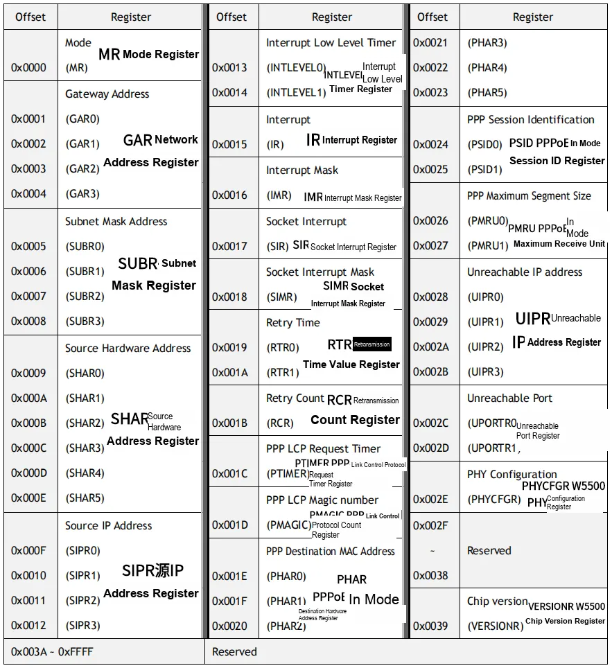
The meanings of the respective registers are as follows:
- MR (Mode Register): Used for the configuration of software reset, Ping block mode and PPPoE mode
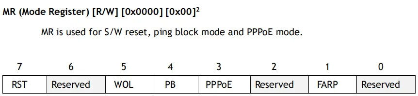
- GAR (Gateway Address Register): Configure the gateway IP Address of the device
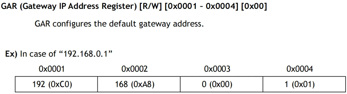
- SUBR (Subnet Mask Register): Configure the subnet mask of the device
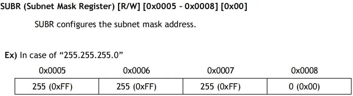
- SHAR (Source Hardware Address Register): Configure the MAC address of the device
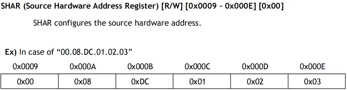
- SIPR (Source IP Address Register): Configure the IP Address of the device
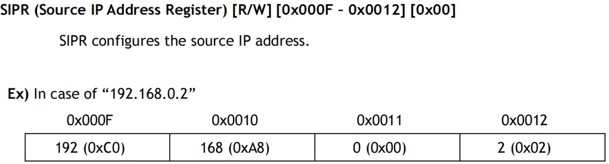
- INTLEVEL (Interrupt Low-level Timer Register): Configures the time value of the interrupt low-level timer.
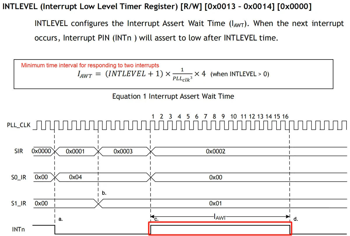
- IR (Interrupt Register): Displays the current interrupt status
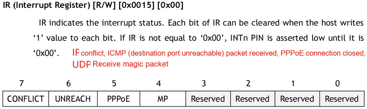
- IMR (Interrupt Mask Register): configures interrupt masking
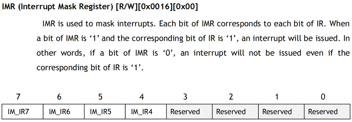
- SIR (Socket Interrupt Register): Displays the current socket interrupt status
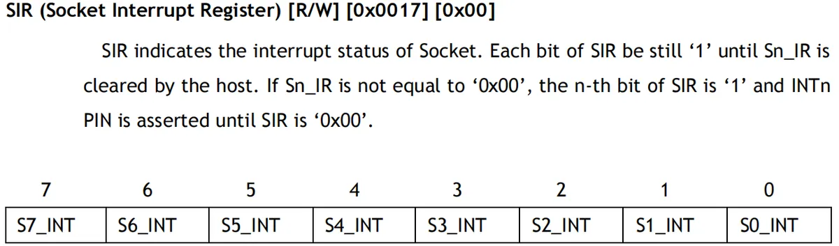
- SIMR (Socket Interrupt Mask Register): Configures the socket interrupt mask
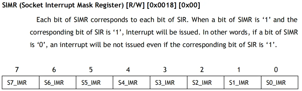
- RTR (Retransmission Time Value Register): configures the time value for retransmission
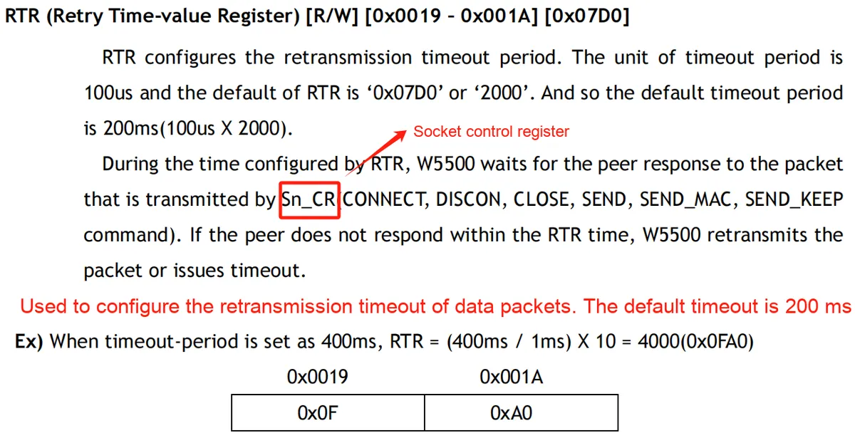
- RCR (Retransmission Count Register): Configure the number of retransmissions
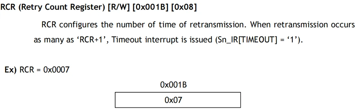
- PTIMER (PPP Link Control Protocol Request Timer Register): A timer that configures the interval for PPP to send LCP echo requests
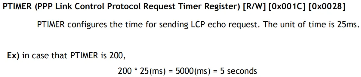
- PMAGIC (PPP Link Control Protocol Magic Number Register): Configures the magic number used by PPP in LCP Echo-Request packets
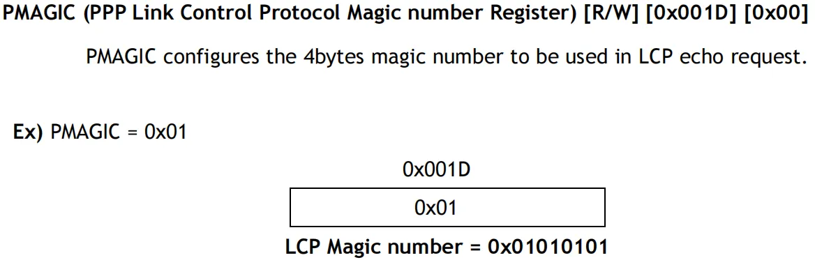
- PHAR (Destination hardware Address Register in PPPoE mode): Configure the destination MAC address of the PPPoE server in PPPoE mode
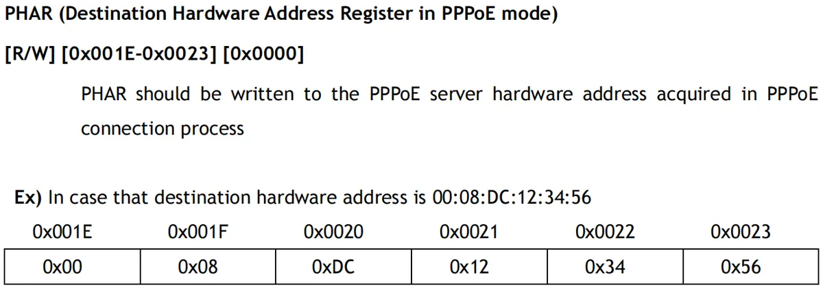
- PSID (Session ID Register in PPPoE Mode): Configure the PPPoE session ID
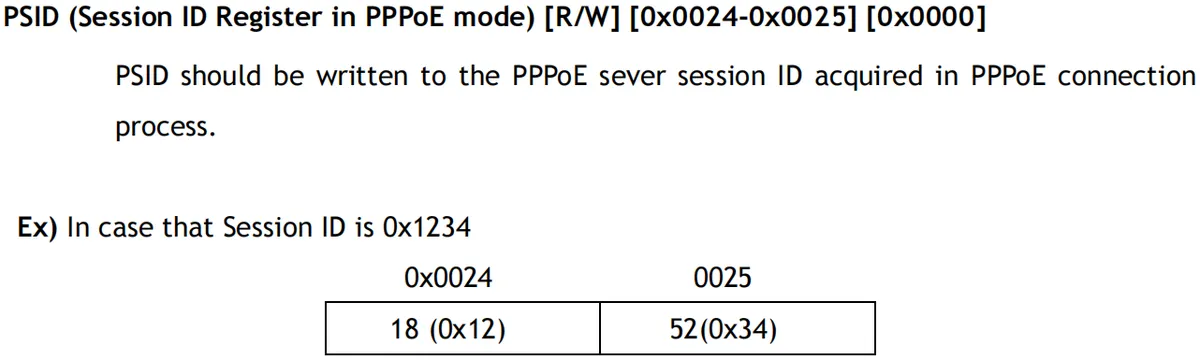
- PMRU (Maximum Receive Unit in PPPoE mode): Configure the PPPoE Maximum Receive Unit
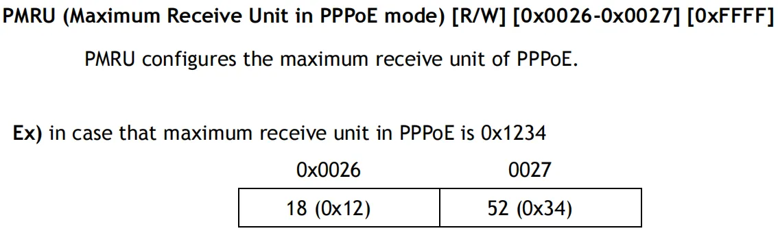
- UIPR (Unreachable IP Address Register): Configures the last unreachable IP Address

- UPORTR (Unreachable Port Register): Configures the last unreachable port
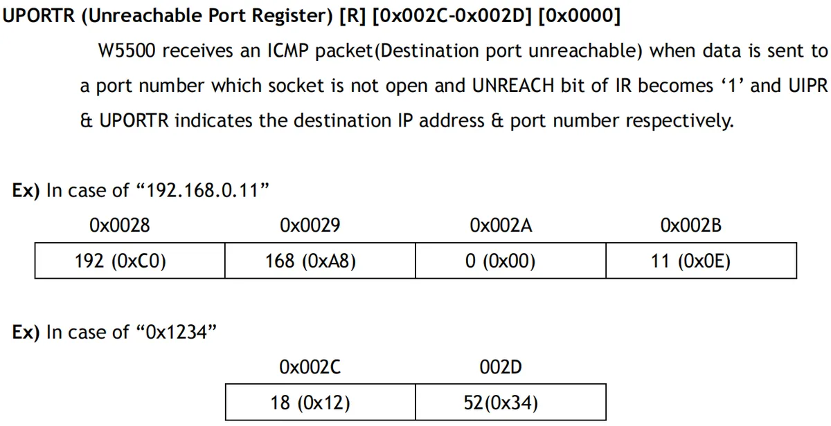
- PHYCFGR (W5500 PHY Configuration Register): Configures the PHY operation mode and performs a reset

- VERSIONR (W5500 Chip Version Register): Displays the chip version number

For the detailed definition and operation method of each register, please refer to Section 4.1 of the original document:
http://www.boccn.com.cn/artupfile/2014-02-11/02014021111343613482.pdf
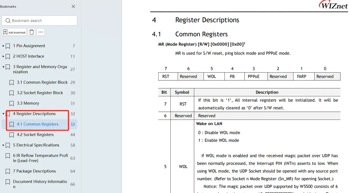
1.2.4.3 Socket Register Block
The W5500 chip supports 8 communication channels, each of which is controlled via the Socket n register block (when 0 ≤ n ≤ 7). The n value of the Socket n register can be selected through BSB[4:0] in the SPI frame.
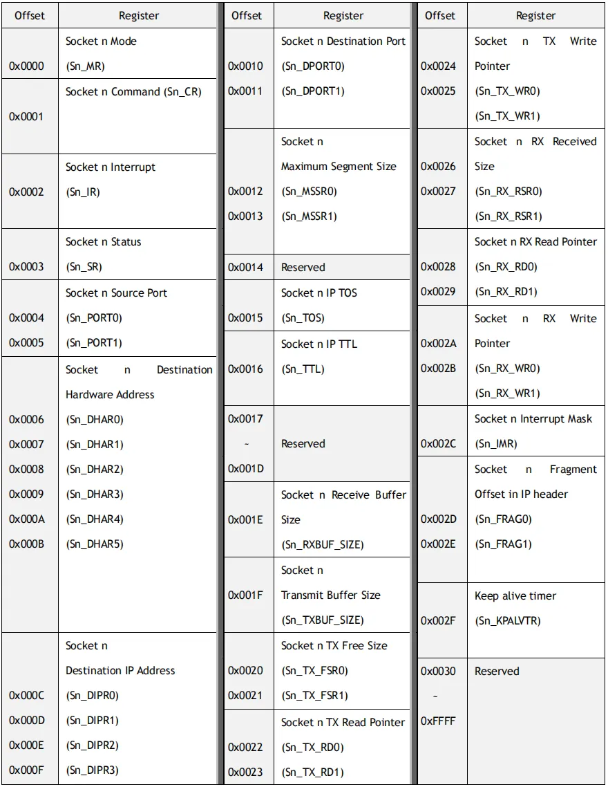
The table below briefly explains the functions of the registers in each Socket n register block.
| Offset address | Register name | Description |
|---|---|---|
| 0x0000 | Socket n Mode (Sn_MR) | Configures the operating mode and protocol type of Socket n |
| 0x0001 | Socket n Command (Sn_CR) | Used to issue Socket commands, such as open connection, close connection, send data, etc. |
| 0x0002 | Socket n Interrupt (Sn_IR) | Reads the interrupt status of the Socket. |
| 0x0003 | Socket n Status (Sn_SR) | Reads the current status of the Socket, such as connection status, receive/send status, etc. |
| 0x0004 | Socket n Source Port (Sn_PORT0) | Configures the upper 8 bits of the Socket source port number |
| 0x0005 | Socket n Source Port (Sn_PORT1) | Configures the lower 8 bits of the Socket source port number |
| 0x0006~ 0x000B | Sn_DHAR (Socket n Destination Hardware Address Register) | Used to configure the destination hardware (MAC) address of Socket n when using the SEND_MAC command in UDP mode |
| 0x000C~ 0x000F | Sn_DIPR (Socket n Destination IP Address Register) | Register used to store the destination IP address of Socket n |
| 0x0010~ 0x0011 | Sn_DPORT (Socket n Destination Port Register) | Used to configure or indicate the destination port number of Socket n |
| 0x0012 | Socket n Maximum Segment Size (Sn_MSSR0) | Register used to set and get the TCP Maximum Segment Size (MSS), corresponding to the upper 8 bits of the MSS value |
| 0x0013 | Socket n Maximum Segment Size (Sn_MSSR1) | Register used to set and get the TCP Maximum Segment Size (MSS), corresponding to the lower 8 bits of the MSS value |
| 0x0014 | Reserved | Reserved for future extension or debugging |
| 0x0015 | Socket n IP TOS (Sn_TOS) | Used to configure the TOS (Type of Service field) in the IP header of socket n |
| 0x0016 | Socket n IP TTL (Sn_TTL) | Used to configure the TTL (Time To Live field in the IP header) of socket n |
| 0x0017 ~ 0x001D | Reserved | Reserved for future extension or debugging |
| 0x001E | Socket n Receive Buffer Size (Sn_RXBUF_SIZE) | Used to configure the receive buffer block size of socket n; the receive buffer block size of socket n can be set to 1, 2, 4, 8 or 16 KB |
| 0x001F | Socket n Transmit Buffer Size (Sn_TXBUF_SIZE) | Used to configure the transmit buffer block size of socket n; the transmit buffer block size of socket n can be set to 1, 2, 4, 8 or 16 KB |
| 0x0020 | Socket n TX Free Size (Sn_TX_FSR0) | Indicates the upper 8 bits of the free size of the socket n TX buffer |
| 0x0021 | Socket n TX Free Size (Sn_TX_FSR1) | Indicates the lower 8 bits of the free size of the socket n TX buffer |
| 0x0022 | Socket n TX Read Pointer (Sn_TX_RD0) | Configures the upper 8 bits of the Socket transmit buffer read pointer |
| 0x0023 | Socket n TX Read Pointer (Sn_TX_RD1) | Configures the lower 8 bits of the Socket transmit buffer read pointer |
| 0x0024 | Socket n TX Write Pointer (Sn_TX_WR0) | Configures the upper 8 bits of the Socket transmit buffer write pointer |
| 0x0025 | Socket n TX Write Pointer (Sn_TX_WR1) | Configures the lower 8 bits of the Socket transmit buffer write pointer |
| 0x0026 | Socket n RX Received Size (Sn_RX_RSR0) | Reads the upper 8 bits of the received data size in the Socket receive buffer |
| 0x0027 | Socket n RX Received Size (Sn_RX_RSR1) | Reads the low 8 bits of the received data size in the Socket receive buffer |
| 0x0028 | Socket n RX Read Pointer (Sn_RX_RD0) | Configures the high 8 bits of the Socket receive buffer read pointer |
| 0x0029 | Socket n RX Read Pointer (Sn_RX_RD1) | Configures the low 8 bits of the Socket receive buffer read pointer |
| 0x002A | Socket n RX Write Pointer (Sn_RX_WR0) | Configures the high 8 bits of the Socket receive buffer write pointer |
| 0x002B | Socket n RX Write Pointer (Sn_RX_WR1) | Configures the low 8 bits of the Socket receive buffer write pointer |
| 0x002C | Socket n Interrupt Mask (Sn_IMR) | Configures the Socket interrupt mask register, used to mask or allow Socket interrupts |
| 0x002D | Socket n Fragment Offset in IP header (Sn_FRAG0) | Configures the high 8 bits of the fragment offset in the IP header of the Socket packets |
| 0x002E | Socket n Fragment Offset in IP header (Sn_FRAG1) | Configures the low 8 bits of the fragment offset in the IP header of the Socket packets |
| 0x002F | Socket n Keep Alive Timer (Sn_KPALVTR) | Configures the Socket Keep Alive timer, used to keep the connection active. |
| 0x0030 ~ 0xFFFF | Reserved | Reserved for future expansion or debugging. |
For the detailed definition and operation method of each register, please refer to Section 4.2 of the original document:
http://www.boccn.com.cn/artupfile/2014-02-11/02014021111343613482.pdf
1.2.4.4 Memory Organization
The W5500 features 16KB of TX memory and 16KB of RX memory, which serve as the buffer for Sockets.
- TX Memory Allocation: By default, each Socket is allocated 2KB of TX buffer blocks (2KB × 8 = 16KB), and the size can be reconfigured via the
Sn_TXBUF_SIZEregister. After configuration, the TX buffers allocate memory sequentially, and the total buffer size of all Sockets shall not exceed 16KB to avoid data transmission errors. - RX Memory Allocation: Initially, the RX buffer block for each Socket is allocated 2KB (2KB × 8 = 16KB), and the size can be reallocated via the
Sn_RXBUF_SIZEregister. After configuration is completed, the RX buffers allocate memory sequentially; the total buffer size of all Sockets shall not exceed 16KB to avoid data reception errors. - Address Mapping:
- The TX and RX buffers use 16-bit offset addresses (0x0000 to 0xFFFF), which are mapped to a 16KB physical memory space.
Sn_TX_WRandSn_RX_RDregisters are used to control these pointers.
Address Mapping Mechanism
Address mapping refers to the process of mapping the logical addresses of a device (register or memory addresses) to actual addresses in the physical Memory Space. When handling the addresses of transmit and receive buffers, the W5500 adopts the address mapping mechanism: the address range of the W5500's registers and buffers spans from 0x0000 to 0xFFFF, which corresponds to a 64KB logical address space, while the actual size of the TX and RX buffers is 16KB; logically, the W5500 uses the 64KB address range to access these memory regions.This means that the device maps a 64KB address space to 16KB of actual physical memory.
1.2.4.5 Read and Write Data in VDM Variable Data Length Mode
1. Write data
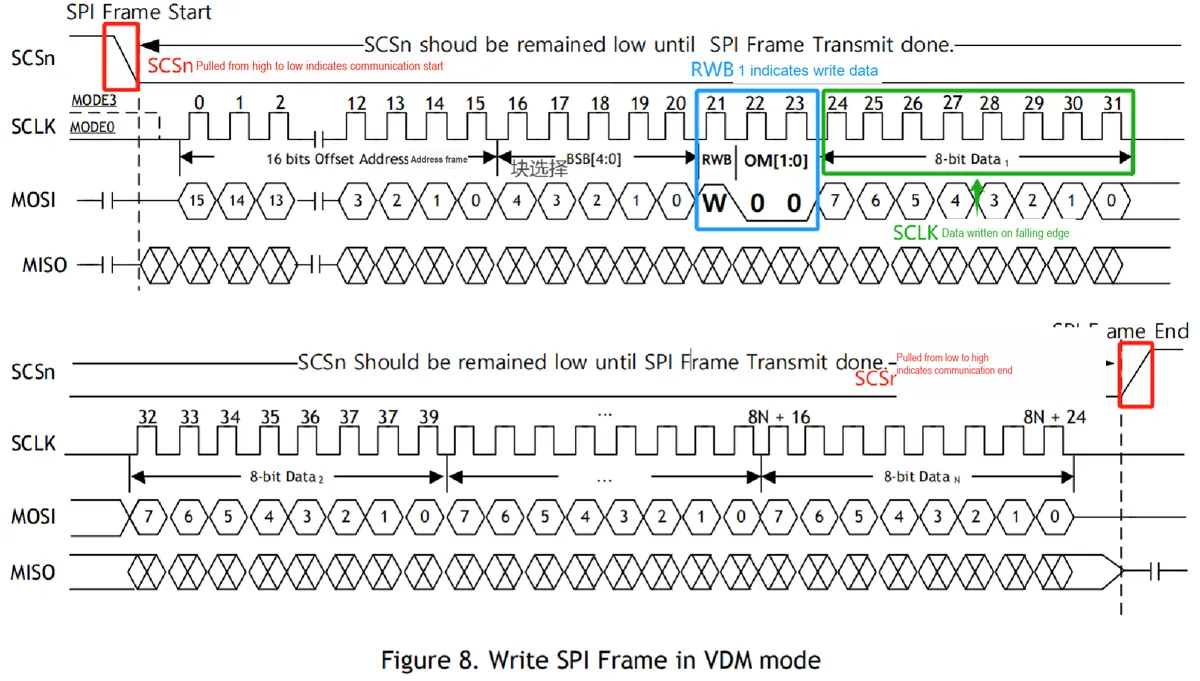
Wherein:
- VDM Mode:
- RWB signal: Set to '1' to indicate that a write operation is to be performed
- OM[1:0]: Set to '00' during the SPI frame control phase to indicate VDM mode
- SPI Frame Transmission Process:
- SCSn Signal: Before transmitting an SPI frame, the external host pulls the SCSn signal from high to low to select the W5500 and prepare for data reception.
- MOSI Signal: The host transmits all data bits to the W5500 via the MOSI signal, and all data bits are synchronized with the falling edge of SCLK.
- SCLK signal: a serial clock signal used to synchronize data transmission
- Transmission completed:
- After completing the SPI frame transmission, the host pulls the SCSn signal from low level to high level (Low-to-High) to terminate the transmission process.
- Sequential data write is supported when the SCSn signal is at low level and the data phase continues
2. Read Data
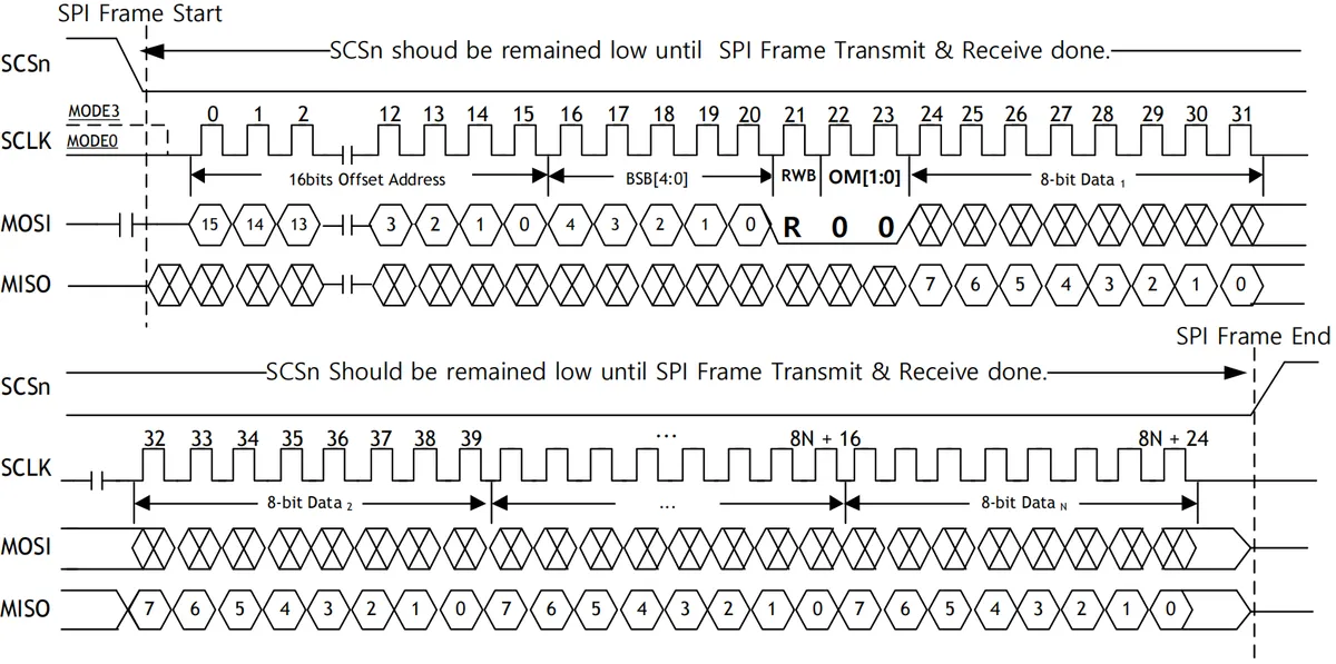
At this point, the RWB signal is set to '0', indicating that a read operation is to be performed.
The start and end procedures of SPI frame transmission are similar to those of a write operation: the master receives all data bits via the MISO signal and synchronizes by sampling the rising edge of SCLK.
1.2.4.6 Read and Write Data in FDM Fixed Data Length Mode
When the external host cannot control the SCSn signal, the FDM mode can be used. In this mode, the SCSn signal should be connected to a low level (always connected to GND), and the host cannot share the SPI bus with other SPI devices.
In FDM mode, the length of the data phase is controlled by the OM[1:0] value ('01'/'10'/'11'), and 1-byte, 2-byte or 4-byte data transmission can be selected.
1. Write data
Take single-byte and double-byte writing as an example:
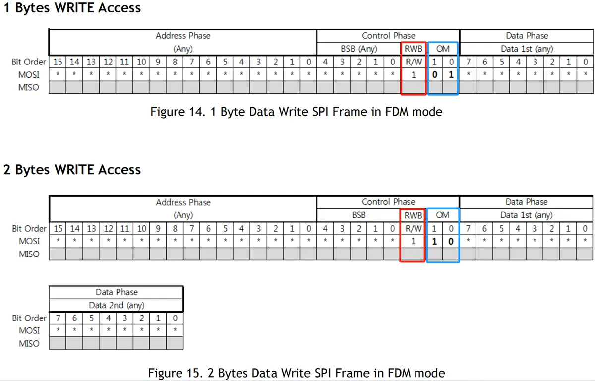
The RWB signal is set to '1' to indicate a write operation; the OM bit can control the number of bytes for data transmission.
2. Read Data
Taking single-byte and double-byte reading as examples:
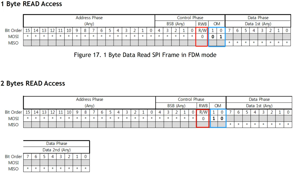
The RWB signal is set to '0' to indicate a read operation; the OM bit can control the number of bytes for data transmission.
2. Software Control Method
2.1 Firmware Flashing for Wiznet W5500-EVB-Pico
Here, the focus of our explanation is not on the usage of the W5500 chip, but on communication based on respective network protocols. In practical applications, we will use Wiznet the MicroPython version of Ethernet communication firmware for the Raspberry Pi Pico provided by the manufacturer, which supports richer network communication functions and runs faster.
We download the MicroPython firmware (v1.23.0 version) for Wiznet W5500-EVB-Pico from the URL in the following link:
https://micropython.org/download/W5500_EVB_PICO/
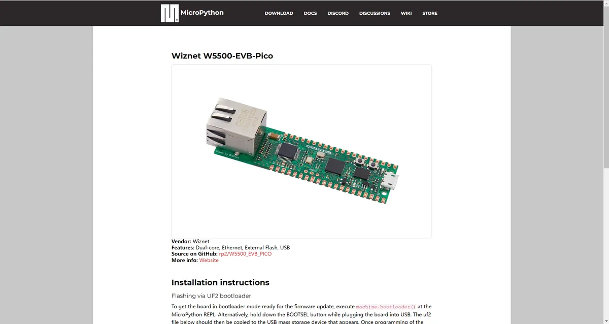
You can also find this Ethernet communication firmware in the reference folder attached to our documentation: elegance-devkit v1\Reference Materials\Official Materials\Official Firmware.
Wiznet W5500-EVB-Pico is an Ethernet evaluation board designed for the Raspberry Pi Pico, with an onboard Wiznet W5500 Ethernet controller chip. This firmware supports the standard TCP/IP protocol stack, including TCP, UDP, DHCP, DNS and other protocols, and provides an easy-to-use API to facilitate upper-layer application development. Following the firmware flashing steps we introduced earlier: hold down the BOOTSEL button, connect the board to the computer via a USB cable, then drag and drop the firmware into the virtual USB drive to complete the flashing process.
It should be noted that when using this firmware for Ethernet communication, the GPIO16, GPIO17, GPIO18, GPIO19, GPIO20 and GPIO21 pins cannot be used, as these pins are by default connected to the W5500 Ethernet chip:
I/O | Pin Name | Description |
I | GPIO16 | Connected to MISO on W5500 |
O | GPIO17 | Connected to CSn on W5500 |
O | GPIO18 | Connected to SCLK on W5500 |
O | GPIO19 | Connected to MOSI on W5500 |
O | GPIO20 | Connected to RSTn on W5500 |
I | GPIO21 | Connected to INTn on W5500 |
On our Fengya No. 1 Base Board - Ethernet & SD Card Expansion Board, the connection between the W5500 module and the Raspberry Pi Pico is shown in the following diagram:
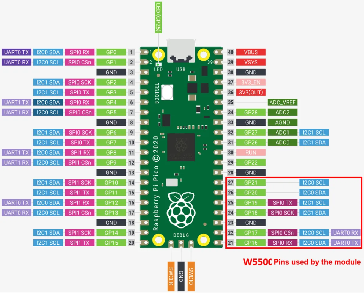
After the flashing is complete, reconnect the Raspberry Pi Pico, open the terminal, and use mpremote to connect:
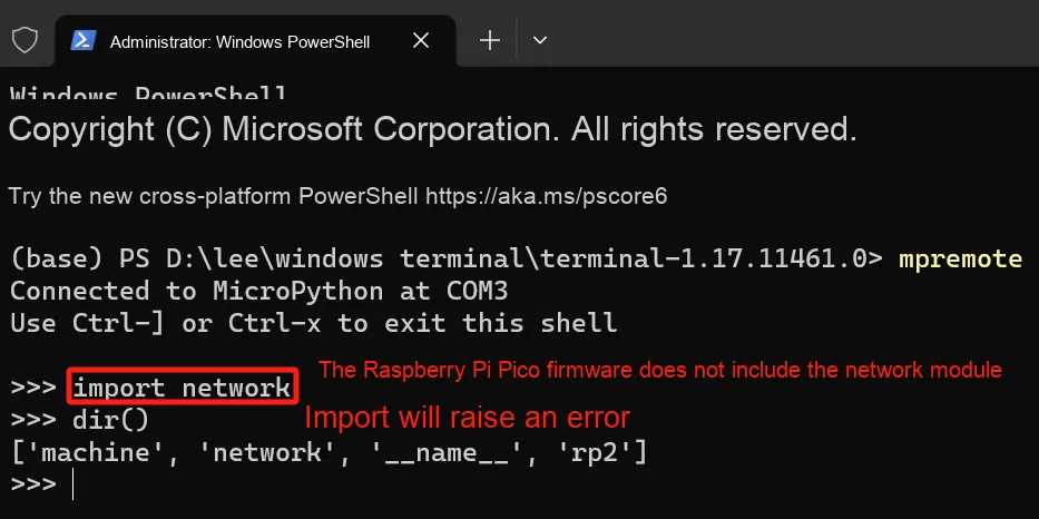
Enter import network statement. If no error is reported, the programming is successful.
2.2 Methods Related to Ethernet Communication Category
When performing TCP, UDP, HTTP and MQTT protocol communication over Ethernet, the following modules and libraries are required:
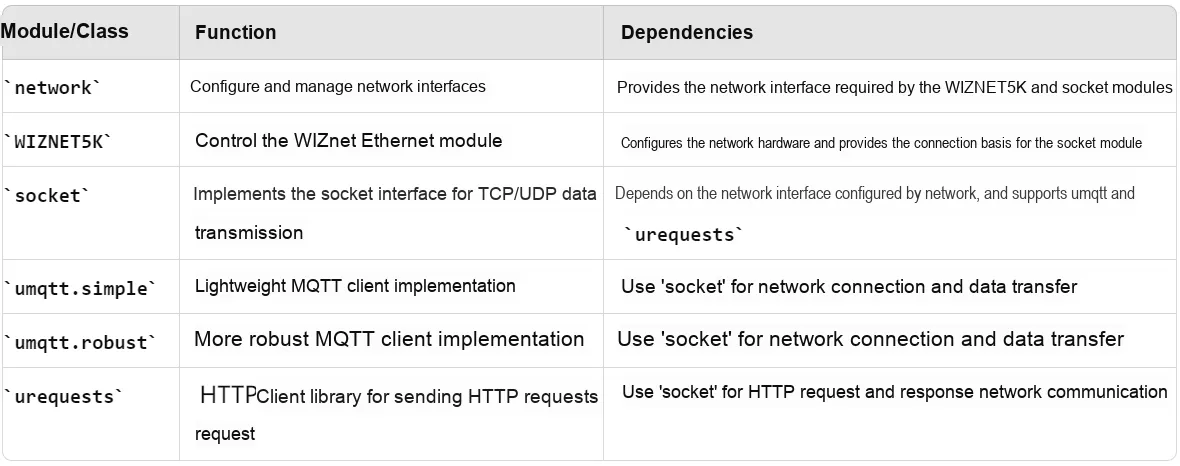
These modules and classes work together to enable MicroPython to implement various network communication functions on embedded devices, ranging from basic TCP/UDP connections to advanced MQTT and HTTP protocols.
2.2.1 network module
In MicroPython, the network module is used to handle network configuration and drivers, providing control over various network interfaces such as Wi-Fi and Ethernet.
For the introduction of the network module, please refer to the link: https://docs.micropython.org/en/latest/library/network.html
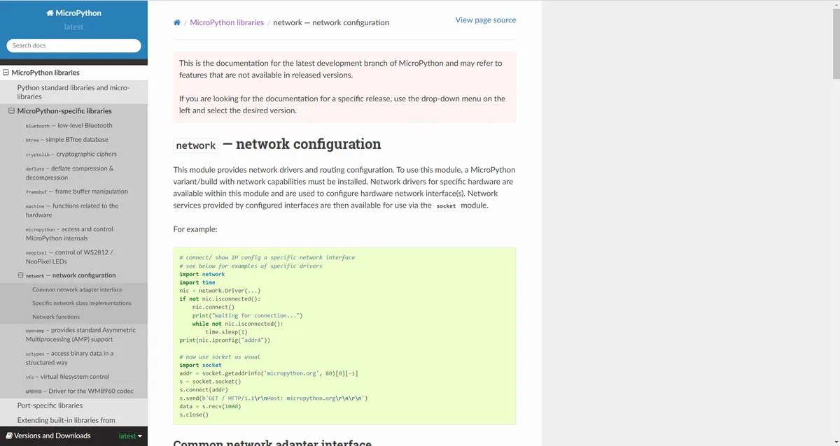
network module provides network drivers and routing configuration functions. It offers control over network hardware, such as Wi-Fi and Ethernet interfaces. This module allows you to set up network connections, obtain interface status, perform scans, and more:
- Manage network interfaces: e. g., activate, deactivate, connect, and disconnect network interfaces
- Configure IP Address: Set static IP address, gateway, DNS server, etc.
- Scan the network: discover available network services
- Query Status: Obtain the current status of the interface, such as signal strength, connection status, etc.
The network module provides an abstract base class AbstractNIC that offers a unified interface for all network interface classes. This class defines a set of methods and attributes that are consistent across all concrete network classes implementing this interface, and this consistency enables different types of network interfaces to be operated via the same methods.
network module defines the following methods:
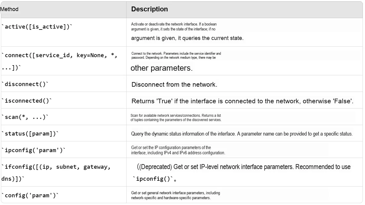
You can refer to the link for details about the parameters, return values and functions of all methods.
Specific network interface classes such as WLAN and WIZNET5K implement the concrete methods of this interface. Through AbstractNIC, MicroPython abstracts different network interfaces (such as Wi-Fi, Ethernet), so that users do not need to care about specific hardware details when programming, and only need to perform network operations according to a unified interface.
2.2.2 WIZNET5K Class
WIZNET5K class is designed to control the WIZnet5x00 series Ethernet modules. It inherits from the abstract base class AbstractNIC, implements and instantiates the control and configuration functions for Ethernet modules, and provides several additional features specific to the WIZnet 5x00 chips. This class is used to initialize and control Ethernet modules, and communicates with the chips via the SPI bus.
For details about the WIZNET5K class, please refer to the following link:
https://docs.micropython.org/en/latest/library/network.WIZNET5K.html
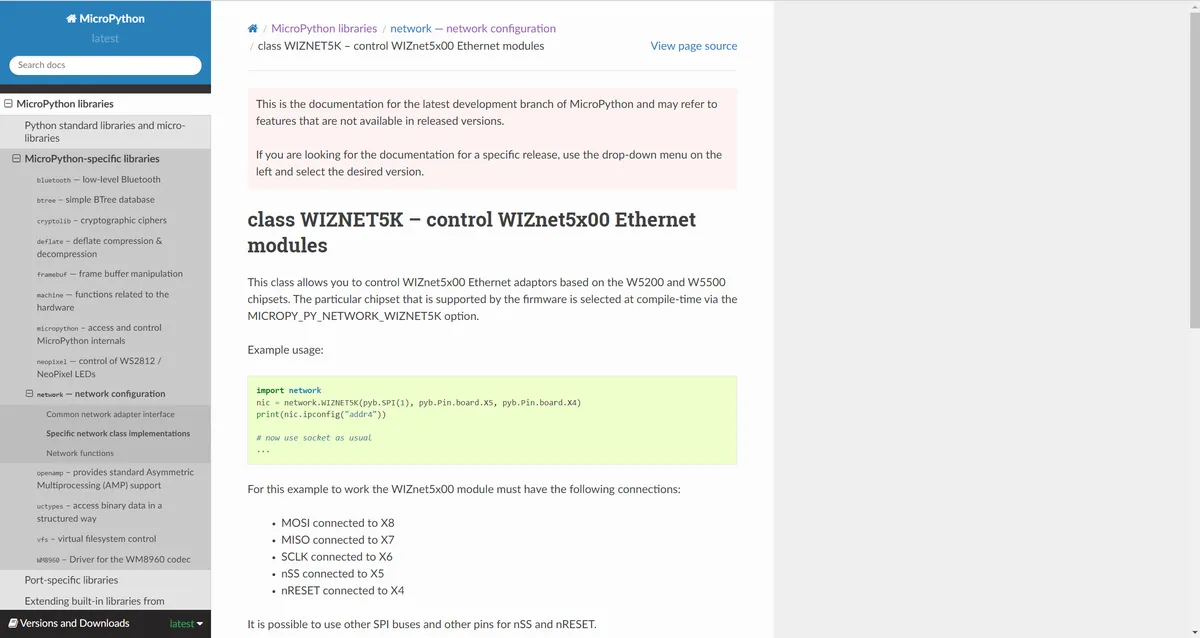
We use the constructor of the WIZNET5K class to create and initialize the WIZnet 5x00 driver object:
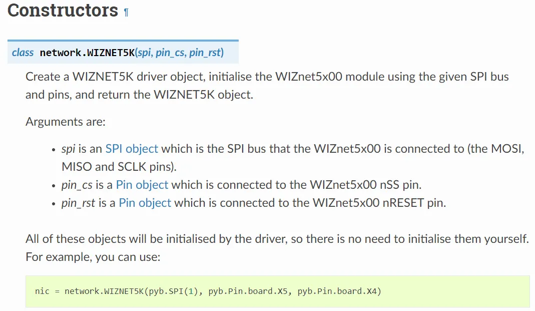
WIZNET5K(spi, pin_cs, pin_rst)
spi: An SPI object representing the SPI bus (including MOSI, MISO and SCLK pins) to which the WIZnet 5x00 module is connectedpin_cs: A Pin object connected to the nSS (chip select) pin of the WIZnet 5x00pin_rst: A Pin object connected to the nRESET pin (reset pin) of the WIZnet 5x00
Other methods include:
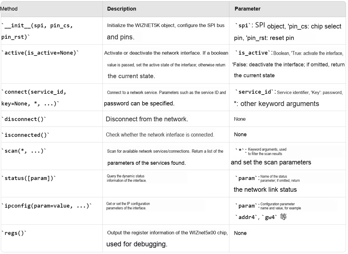
2.2.3 socket module
network module and the socket module are typically used together. First, you use the network module to configure and manage network interfaces, then use the socket module to handle actual data communication. The socket module provides low-level network communication capabilities, allowing you to send and receive data over the network. It offers a socket programming interface that supports network operations for protocols such as TCP and UDP. The socket module can be used to establish network connections, send data, receive data, and more.
For specific information about the socket module, please refer to the following link:
https://docs.micropython.org/en/latest/library/socket.html
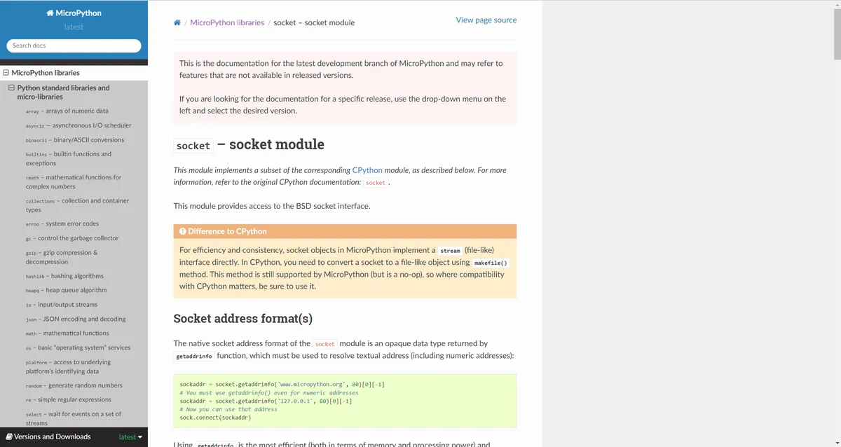
The socket module provides some basic configuration and data conversion methods:
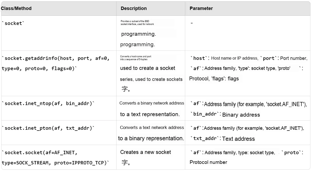
We create a socket via the socket module's socket.socket class for network communication, and the socket.socket class has the following methods:
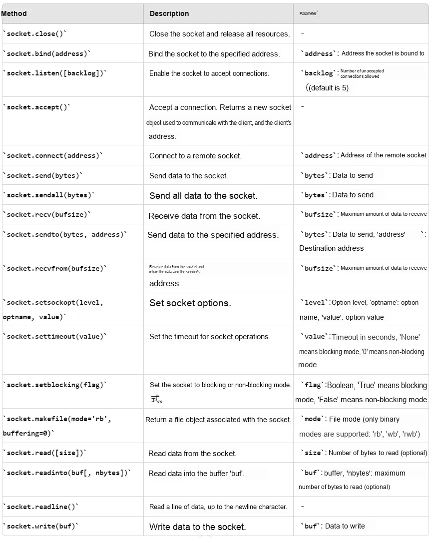
and provides the following constants for configuring parameters:
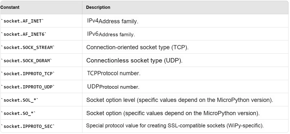
The socket module in MicroPython and the socket module in CPython have the following differences:
- Exception Handling: MicroPython uses
OSErrorin place of CPython'ssocket.errorandsocket.gaierror - Timeout handling: MicroPython uses the
settimeout ()andsetblocking ()methods to configure timeouts and blocking modes, but does not support thesocket.timeoutexception from CPython - File Interface: The
makefile ()method of MicroPython only supports binary mode, and does not support theencoding,errorsandnewlineparameters in CPython
Although the socket module provides basic TCP and UDP protocols, additional modules or libraries are indeed required to implement more advanced protocols such as MQTT and HTTP. These protocols usually come with extra functions and more complex processing, which are generally not included in the basic socket module.
- MQTT Protocol:
umqtt.simple: This is a lightweight MQTT Client library in MicroPython, which is used to handle the basic functions of the MQTT protocol, including connection, publishing, subscription and message receiving. It is suitable for scenarios with relatively low resource requirements.umqtt.robust: This is another MQTT Client library that provides more comprehensive and robust support for the MQTT protocol. It can handle more complex MQTT features such as automatic reconnection and QoS support.
- HTTP Protocol:
urequests: This is a simple HTTP Client library for sending HTTP requests (such as GET, POST, PUT, DELETE) and processing responses. It provides an interface similar to that of the standard Pythonrequestslibrary, but is more lightweight.
2.3 Debugging Software Download
Here, we need to download the NetAssist software and the Advanced IP Scanner software for debugging, both of which can be found in the attached resource folder:
- NetAssist Software: This is a professional Network Diagnostics and analysis tool, whose main functions include network device scanning and topology discovery, port scanning and service detection, and basic Network Diagnostics. It provides rich debugging options and visual analysis interface, and supports multiple protocol parsing.
You can refer to the following link for its download and usage tutorial: https://cloud.tencent.com/developer/article/1739493
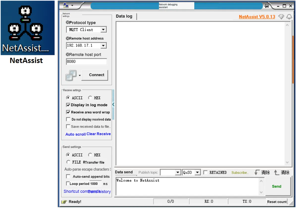
- Advanced IP Scanner: This is a simple and efficient network scanning and management tool. Its main functions include quickly scanning online devices within a network segment, displaying information such as device IP addresses, MAC addresses, and hostnames, and providing basic Network Diagnostics features such as ping tests and port scanning.
You can refer to the following link for its download and usage tutorial: https://blog.csdn.net/Thomas_DUCK/article/details/120843968
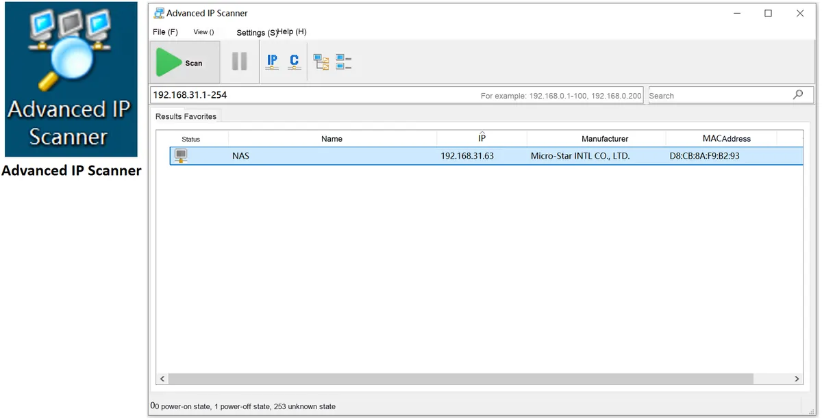
- MQTTX Software: A cross-platform open-source MQTT Client tool designed specifically for the development, debugging and testing of Internet of Things (IoT) applications. It can manage multiple MQTT connections simultaneously, each with configurable parameters such as different server addresses, ports, protocol versions, usernames and passwords. It also provides an intuitive User Interface, allowing users to easily configure and manage MQTT connections, publish and subscribe to topics, and view message history.
For its download and usage tutorial, please refer to the link: https://www.emqx.com/zh/blog/mqtt-x-guideline
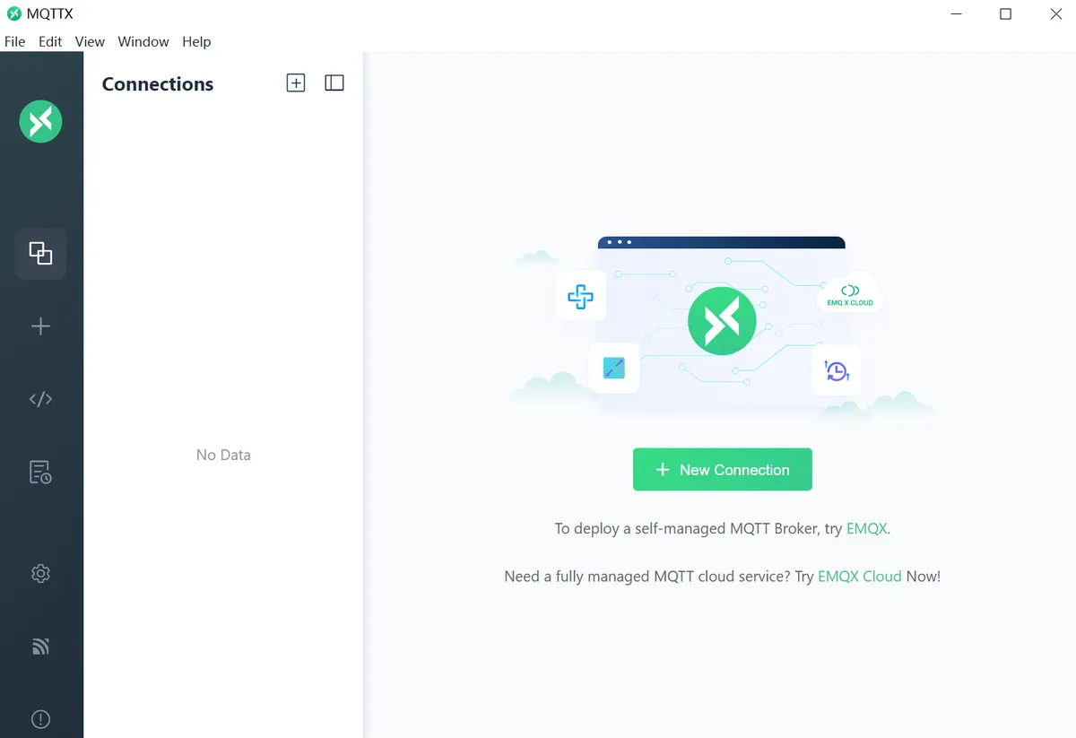
2.4 Preparations
Before connecting a computer to the W5500 Ethernet port via the Ethernet protocol, several preparations are required. First, you need to disable the computer's firewall: you can refer to the link https://www.zhihu.com/question/423956982 for relevant configuration steps.
Then insert the Fengya No. 1 Board - Ethernet & SD Card Expansion Board into the Fengya No. 1 Board - Universal Compatible Expansion Board:
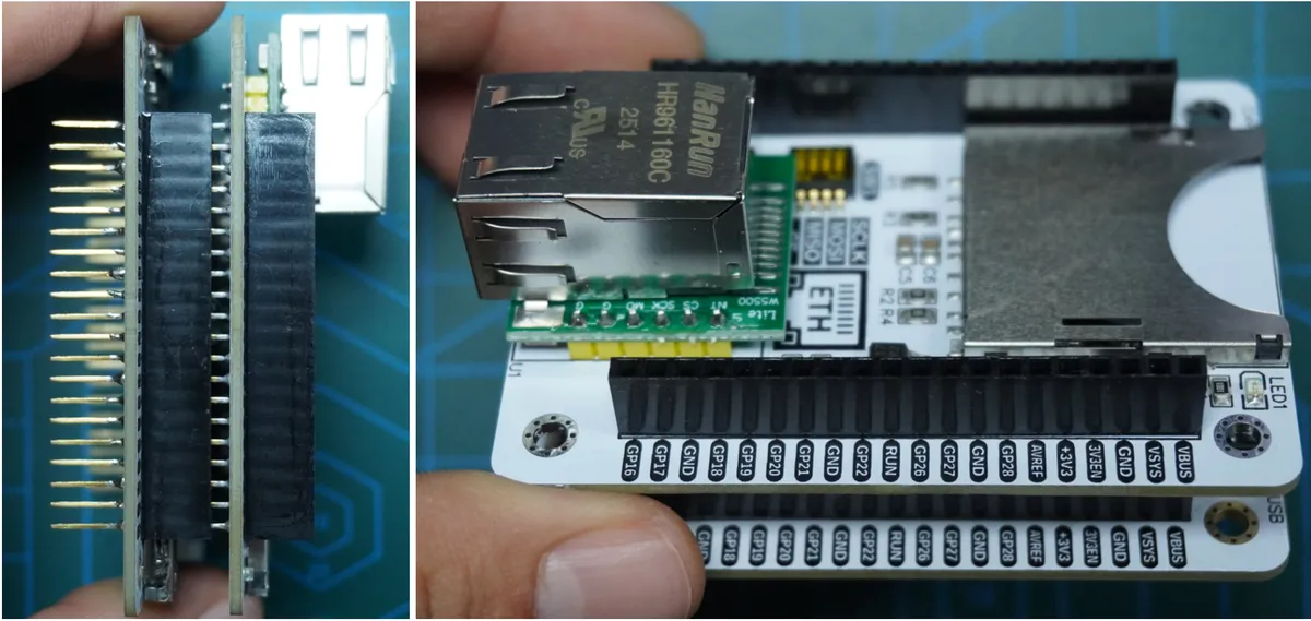
Next, there are two ways to connect the W5500 Ethernet port on the computer and the expansion board:
- Direct connection between a computer and the W5500: Simply use a single Ethernet cable, no additional equipment is required; however, since the W5500 does not support polarity reversal, if your computer does not support
Auto-MDIX, a crossover Ethernet cable is required for the connection; meanwhile, if the network adapter of your computer does not support auto-negotiation, you need to manually configure the Ethernet communication speed and mode. - Connection via a switch: Connect the computer and the W5500 Ethernet port to the same switch using two straight-through network cables. This method eliminates the need for crossover cables, allows easy expansion to connect multiple devices, and enables network traffic and device connection status to be managed via the switch.
Here, we adopt the second method to connect the W5500 module and the computer via a switch.
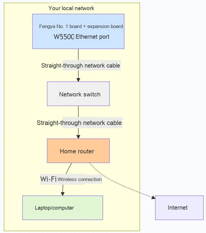
If you use the first method, you need to manually configure the Ethernet communication speed and mode. First, open Network & Internet settings, click Change adapter options:
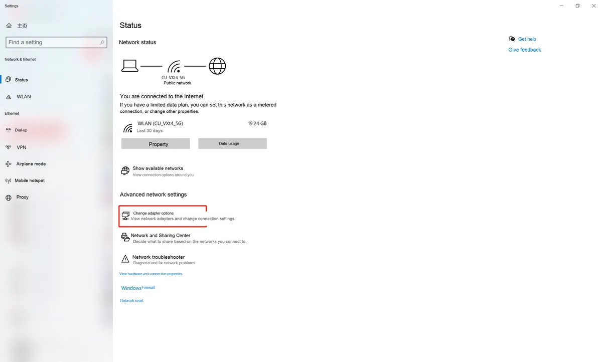
Select Ethernet, right-click Properties, and click Configure:
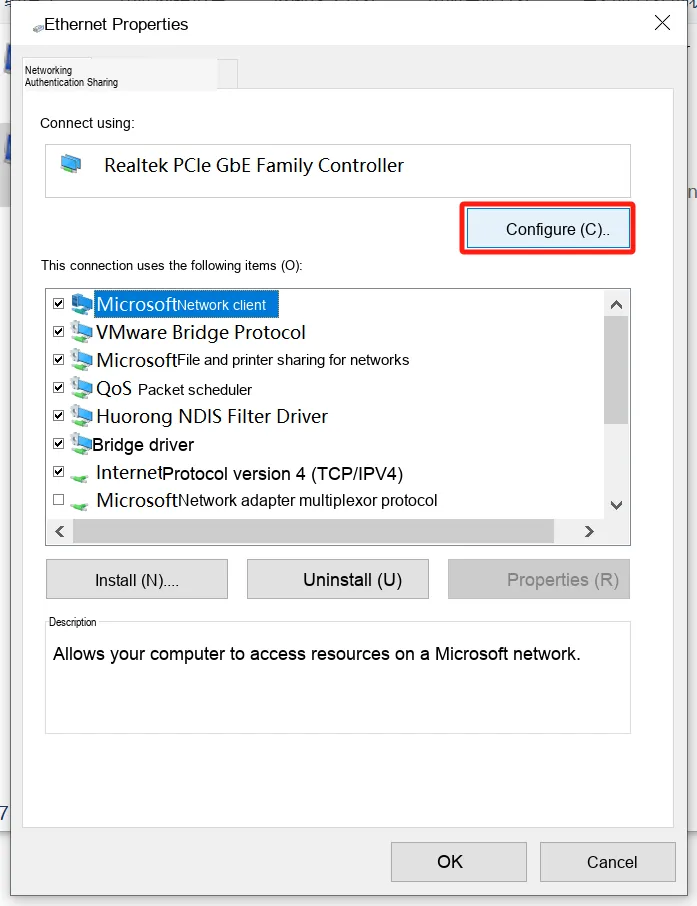
Click Advanced , select Link Speed & Duplex , and set the value to 10 Mbps Full Duplex:
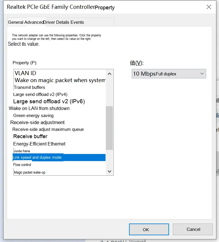
After the modification is completed, click OK to apply the configuration, then set the local IP Address to be in the same network segment as the IP Address set for the W5500, that is, in the Ethernet Properties settings, double-click Internet Protocol Version 4 (TCP/IPv4), and select Use the following IP Address:
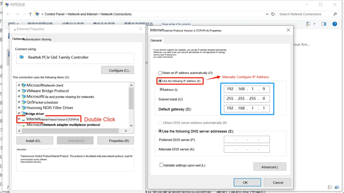
Here, the IP Address is set as follows:
- IP Address:
192.168.1.6(in the same network segment as W5500). - Subnet Mask:
255.255.255.0. - Default Gateway:
192.168.1.1(if applicable).
Click OK to save:
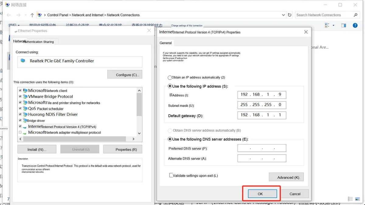
Next, we officially move on to the communication application part of various network protocols.
2.5 Special Notes
In 3.1 TCP Protocol Experiment, 3.2 UDP Protocol Experiment and 3.5.2 HTTP Server Experiment, if you connect the W5500 module Ethernet port of the Raspberry Pi Pico to the computer's Ethernet port via a crossover Ethernet cable, you do not need to modify the IP address and gateway address of the Raspberry Pi Pico, as well as the IP address, subnet mask and default gateway address of the computer in the code, and can directly use the configurations in 2.4 Preparations section.
For the remaining experiments (such as 3.3 DHCP Protocol Experiment, 3.4 DNS Protocol Experiment, 3.5.1 HTTP Client Experiment, and 3.6 MQTT Protocol Experiment), you need to connect the network port of the W5500 module on the Raspberry Pi Pico to the router. At this point, you need to modify the IP address and gateway address settings of the Raspberry Pi Pico in the code accordingly according to the actual network configuration of the router.
Here, for demonstration purposes, after modifying the network configuration of the router, open the terminal and enter the ipconfig command to view the detailed information of the network adapter, including the IP address, subnet mask, default gateway and other network configuration parameters (the computer is connected to the router via WIFI at this time):
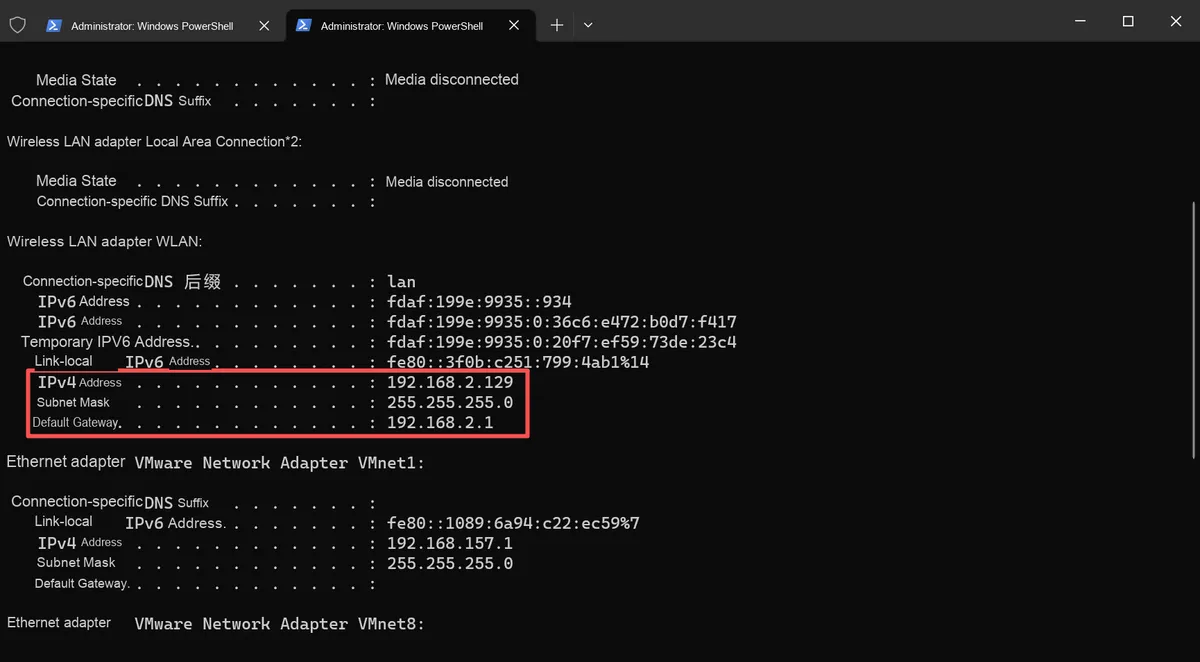
From the output of the ipconfig command above, we can extract the core network configuration information of the LAN where the current router is located, which will serve as the direct basis for modifying the code parameters of the Raspberry Pi Pico W5500 module:
- LAN segment:
192.168.2.x(as indicated by the computer's IPv4 address192.168.2.129) - Subnet Mask:
255.255.255.0(consistent with the computer's subnet mask) - Router gateway address:
192.168.2.1(i. e. the gateway to be configured for the W5500 module)
Based on this, we need to, in the experiment codes that require router connection including 3.3 DHCP Protocol Experiment, 3.4 DNS Protocol Experiment and others, adjust the network configuration parameters of the Raspberry Pi Pico in a targeted manner, locate the part in the code that defines netinfo (usually containing the device IP, subnet mask, gateway, and DNS), and replace the original parameters of the 192.168.1.x network segment with the current LAN configuration:
# New configuration (router connection scenario, based on ipconfig results)
ip = '192.168.2.20'  # Must be in the same subnet as the computer and not used by other devices on the LAN (e.g. a free IP between 192.168.2.20-100)
sn = '255.255.255.0'        # Exactly the same as the computer's subnet mask
gw = '192.168.2.1'          # Same as the router gateway address (i.e. the computer's default gateway)
dns = '8.8.8.8'     # Optional: a public DNS in China, or the router's own DNS (usually the same as the gateway, i.e. 192.168.2.1)
netinfo = (device_ip, sn, gw, dns)
After the code modification is completed and flashed to the Raspberry Pi Pico, check the network initialization result via the serial terminal:
- If the display shows
ip : 192.168.2.20(static IP scenario) orip : 192.168.2.x(DHCP automatic assignment scenario),gw : 192.168.2.1, it indicates that the network configuration matches the router successfully; - When performing subsequent DNS resolution (such as the query in Experiment 3.4 for
www.cnblogs.com) or HTTP Client requests (such as in Experiment 3.5.1), if the IP can be obtained normally or data can be received successfully, it proves that the router connection and parameter configuration are correct.
Through the above steps, the W5500 module of the Raspberry Pi Pico can be ensured to integrate into the local area network of the current router, meeting the requirements for "external network connectivity" in experiments such as DHCP, DNS, and HTTP Client (for example, DNS resolution requires access to a public DNS server, and the MQTT protocol requires connection to a cloud server, etc.).
Alternatively, directly insert the following DHCP configuration logic into the w5x00_init () function, between the lines "Activate network interface (nic.active (True))" and "Wait for network connection (while not nic.isconnected ())". The function will first print "Configuring DHCP" and attempt to dynamically obtain the IP, subnet mask, gateway and DNS parameters from the router via nic.ifconfig ('dhcp')(this adapts to scenarios requiring router connection such as the 3.3 DHCP Protocol Experiment and 3.4 DNS Protocol Experiment, eliminating the need for manual IP modification):
try:
        print("\r\nConfiguring DHCP")
        # Try to use DHCP to dynamically obtain network configuration such as IP address, subnet mask, gateway and DNS server
        nic.ifconfig('dhcp')
    except:
        print("\r\nDHCP fails, use static configuration")
        # If DHCP fails, use the static IP address configuration
        nic.ifconfig(netinfo)
3. Application Examples
3.1 TCP Protocol Experiment
3.1.1 Ping Test Experiment
Here, we first conduct a ping test experiment: the Raspberry Pi Pico controls the w5500 chip to establish a network connection using the static IP Address configured by the user, after which we use the ping command on a computer to test the connection speed and latency.
ping test is a commonly used Network Diagnostics tool, which is used to check network connectivity and latency. The basic principle of the ping test is as follows:
- Sending ICMP Echo Request:
The pingtool sends anICMP(Internet Control Message Protocol) echo request packet to the target device - Waiting for response: After receiving the request, the target device returns an ICMP echo reply packet
- Calculation time:
The pingtool records the time from sending a request to receiving a response, usually in milliseconds (ms).
We can directly open the terminal and use the ping command in the terminal to complete the Ping test:
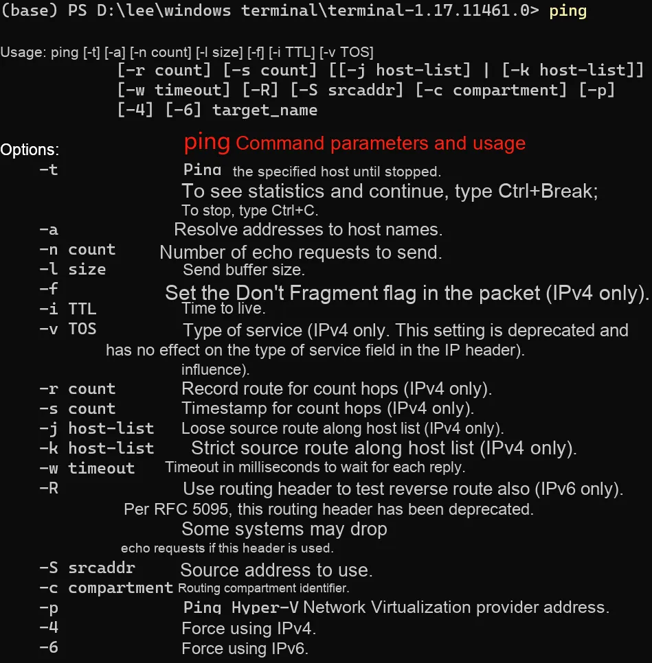
First, we use the ipconfig command to view the detailed information of the network adapter, including the IP address, subnet mask, default gateway and other network configuration parameters:
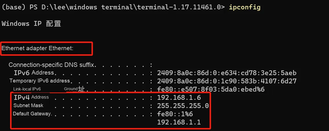
In the Ethernet Adapter Ethernet section, the network configuration of the computer's Ethernet (wired network) connection is described in detail. As you can see, the host address of our computer is 192.168.1.6. If you connect the ETH direct connection Ethernet cable to the W5500 Ethernet module and the computer, then this address is the host address; but if your computer is connected via WiFi to the same router that the W5500 Ethernet module is connected to, then the Wireless LAN Adapter WLAN section's IPv4 address is the host address:
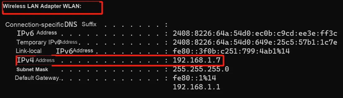
Next, we will configure the W5500 module such that its subnet mask and default gateway are identical to those of the host address.
We try to ping the computer host, and add the IP Address of the computer host after the ping command ping 192.168.1.6:
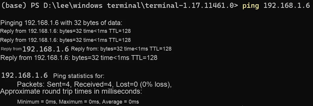
As can be seen, several types of data are returned:
- Packet Size: The size of the data packet to be sent, which is typically 32 bytes;
- Time (
time): Round-trip time, which refers to the time from sending a request to receiving a response; - Time to Live (
TTL, Time to Live): the maximum number of hops a data packet can traverse in a network, which reflects the number of routers the packet has passed through.
We can specify the data packet size as -l data_size by adding the parameter data_size:
ping -l 64 192.168.1.6
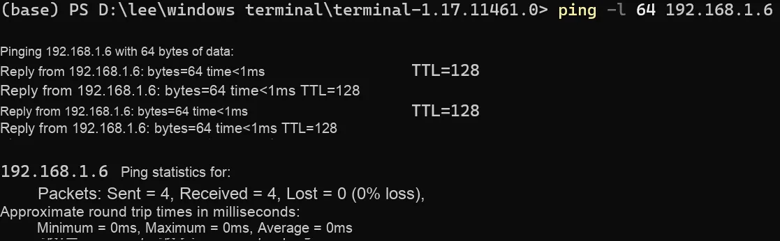
You can also add the -t parameter to specify continuous ping:
ping -t 192.168.1.6
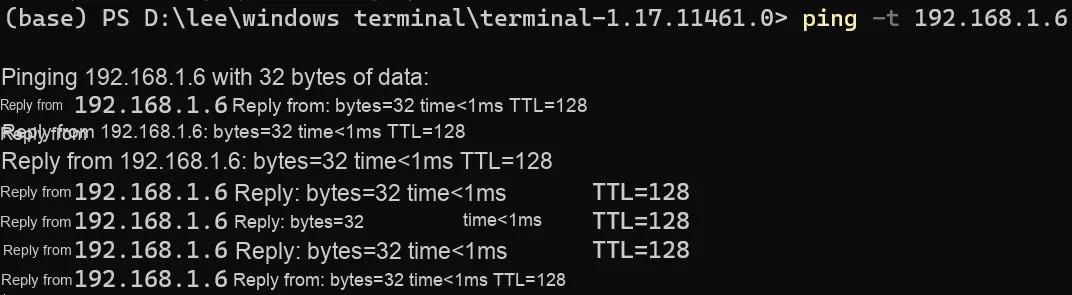
The following code can be found in the material package we provide elegance-devkit v1\Demo\40 ETH_TCP_Ping folder.
Next, we initialize the W5500 network chip, and configure network parameters such as a static IP address, then continuously test network connectivity via the ping command in the terminal:
# Python env   : MicroPython v1.23.0 on Wiznet W5500
# -*- coding: utf-8 -*-
# @Time    : 2024/8/6 10:17 PM
# @Author  : Li Qingshui
# @File    : w5x00_Ping_Test.py
# @Description : Ethernet experiment, performing a ping test

# ======================================== Import Modules ========================================

# Import the socket module
from usocket import socket
# Import hardware-related modules
from machine import Pin,SPI
# Import network-related modules
import network
# Import time-related modules
import time

# ======================================== Global Variables ============================================

# ======================================== Functions ============================================

# Initialize the network interface
def w5x00_init() -> network.WIZNET5K:
    """
    Initialize a network.WIZNET5K instance, set a static IP address, and connect to the network.

    Args:
        None

    Returns:
        network.WIZNET5K: The network.WIZNET5K instance that was initialized and connected successfully.

    Raises:
        None
    """
    # Initialize the SPI object
    spi = SPI(0, 2_000_000, mosi=Pin(19), miso=Pin(16), sck=Pin(18))
    # Instantiate the network.WIZNET5K class, passing in the chip select pin CS and reset pin RST
    nic = network.WIZNET5K(spi, Pin(17), Pin(20))
    # Activate the network interface
    nic.active(True)
    # Set the static IP address: host address, subnet mask, gateway address, and DNS server address
    nic.ifconfig(('192.168.1.20', '255.255.255.0', '192.168.1.1', '8.8.8.8'))

    # Loop while the network is not connected
    while not nic.isconnected():
        time.sleep(1)
        # Output register information
        print(nic.regs())

    # Print the configured IP address
    print("IP Address:", nic.ifconfig()[0])
    print("Subnet Mask:", nic.ifconfig()[1])
    print("Gateway:", nic.ifconfig()[2])
    print("DNS:", nic.ifconfig()[3])

    # Return the network.WIZNET5K instance
    return nic

# ======================================== Custom Classes ============================================

# ======================================== Initialization ==========================================

# Delay 3 s, wait for the device to power up
time.sleep(3)
# Print debug information
print("FreakStudio : Using W5x00 Ethernet to do Ping Test")

# Create the LED object
led = Pin(25, Pin.OUT)
# Initialize the network interface
nic = w5x00_init()

# ========================================  Main Program  ===========================================

while True:
    # Blink the LED to show the code is still running
    led.value(1)
    time.sleep(1)
    led.value(0)
    time.sleep(1)
    # Use the Ping command in the terminal to test the connection
    print("try ping", nic.ifconfig()[0])
When setting the host address for a static IP Address, we can use Advanced IP Scanner software to scan and check the host addresses of devices connected to the current network, then select an unoccupied host address to configure the host address of the w5500 chip:
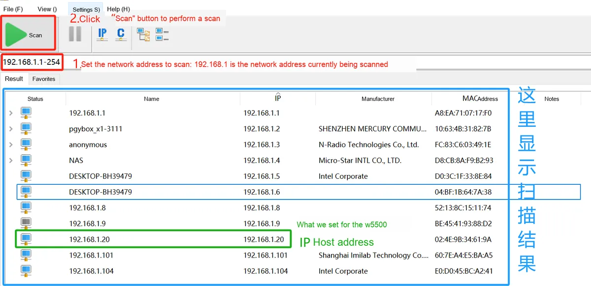
3.1.1 Application Experiment.mp4 2.8 MB
Here, we use 192.168.1.20 as the host address of the w5500 chip. Burn the code and open the remote terminal:
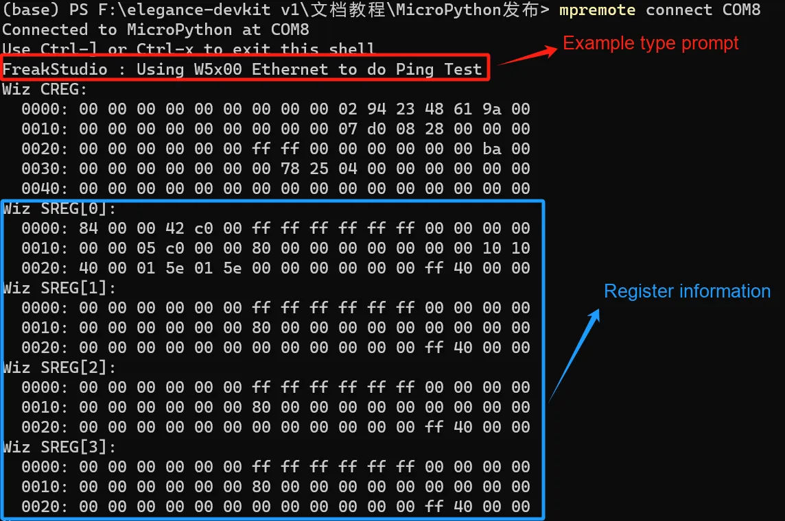
3.1.2 Application Experiment.mp4 4.2 MB
It can be seen that the output will first display w5500 the relevant data of the chip registers, which can be used for debugging, where:
- Wiz CREG: This is the
W5x00chip's general-purpose register, which stores the chip's basic configuration information, such as hardware version,MACaddress, etc. These pieces of information are usually read and saved during initialization. - Wiz SREG[0]-[3]: These are
W5x00'sSocketregisters. EachSockethas a set of associated registers, and the register contents of 4Socketsare presented here.
Then the configured static IP Address is output. After the connection with the computer is established successfully, it outputs try ping 192.168.1.20 debug info:

We open another terminal and enter ping 192.168.1.20, and we can see that the ping test has been successfully verified.
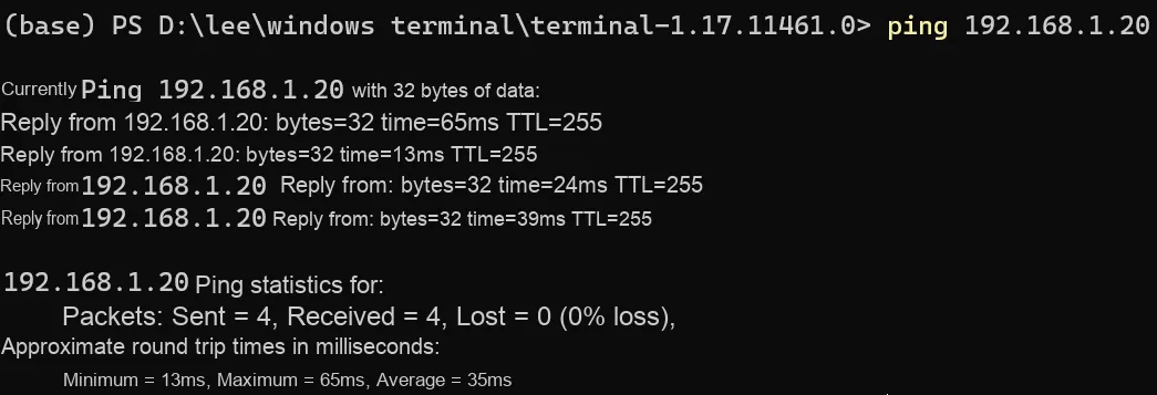
3.1.2 TCP Client Experiment
The following code can be found in the material package we provide, in the elegance-devkit v1\Demo\41 ETH_TCP_Client folder.
In this experiment, we will configure w5500 and Raspberry Pi Pico to act as TCP protocol Client, and transmit relevant data to the TCP server created in the network debugging assistant software. The sample code is as follows:
# Python env   : MicroPython v1.23.0 on Wiznet W5500
# -*- coding: utf-8 -*-
# @Time    : 2024/8/7 9:12 PM
# @Author  : Li Qingshui
# @File    : main.py
# @Description : Ethernet experiment, TCP client test

# ======================================== Import Modules ========================================

# Import the socket module used to create and manage network connections
from usocket import socket
# Import hardware-related modules
from machine import Pin,SPI
# Import time-related modules
import time
# Import network-related modules
import network

# ======================================== Global Variables ============================================

# TCP client IP address
ip = '192.168.1.20'
sn = '255.255.255.0'
gw = '192.168.1.1'
dns= '8.8.8.8'
# Tuple object used for the network connection
netinfo=(ip, sn, gw, dns)

# TCP server IP address: the IP address of the host computer
destip = '192.168.1.6'
# TCP server port
destport = 8080
# Tuple object used for the network connection
conn_info = (destip, destport)

# Global variable indicating the connection state
conn_flag = False

# ======================================== Functions ============================================

# Initialize the network interface
def w5x00_init() -> network.WIZNET5K:
    """
    Initialize a network.WIZNET5K instance, set a static IP address, and connect to the network.

    Args:
        None

    Returns:
        network.WIZNET5K: The network.WIZNET5K instance that was initialized and connected successfully.

    Raises:
        None
    """
    # Declare global variables
    global netinfo

    # Initialize the SPI object
    spi = SPI(0, 2_000_000, mosi=Pin(19), miso=Pin(16), sck=Pin(18))
    # Instantiate the network.WIZNET5K class, passing in the chip select pin CS and reset pin RST
    nic = network.WIZNET5K(spi, Pin(17), Pin(20))
    # Activate the network interface
    nic.active(True)
    # Set the static IP address: host address, subnet mask, gateway address, and DNS server address
    nic.ifconfig(netinfo)

    # Loop while the network is not connected
    while not nic.isconnected():
        time.sleep(1)
        # Output register information
        print(nic.regs())

    # Print the configured IP address
    print('ip :', nic.ifconfig()[0])
    print('sn :', nic.ifconfig()[1])
    print('gw :', nic.ifconfig()[2])
    print('dns:', nic.ifconfig()[3])

    # Return the network.WIZNET5K instance
    return nic

def client_loop() -> None:
    """
    Client loop: continuously receive data sent by the server and echo it back.

    This function tries to connect to the specified server address and port, and receives the data sent by the server after the connection succeeds.
    If data is received, it is sent back to the server. If the connection is lost, it tries to reconnect.

    Args:
        None

    Returns:
        None

    Raises:
        None
    """

    # Declare global variables
    global conn_flag

    # Create a socket object
    s = None

    # Loop to receive and send
    while (True):
        # If not currently connected
        if not conn_flag:
            # If the socket exists, close it first
            if s:
                try:
                    s.close()
                except:
                    pass

            # Delay 100 ms before re-creating the socket
            time.sleep_ms(100)

            # Create a new socket object
            try:
                s = socket()
                print("Created new socket")
            except:
                print("Failed to create socket")
                # Failed to create the socket, continue the loop
                continue

            # Try to connect to the specified IP address and port
            try:
                s.connect(conn_info)
                conn_flag = True
                print("Loopback client Connect!")
            except:
                print('connect error')
                conn_flag = False

        # If already connected
        elif conn_flag and s:
            try:
                # Try to receive up to 2048 bytes of data
                data = s.recv(2048)
                # Check whether data was received
                if data:
                    # Decode the received data into a string
                    data_str = data.decode('utf-8')
                    print(f'recv from {conn_info[0]}:{conn_info[1]}: {data_str}')
                    # Send the data back
                    s.send(data)
                else:
                    # Receiving empty data means the connection has been closed
                    print('Connection closed by server')
                    conn_flag = False
            except:
                print('disconnect')
                conn_flag = False

# ======================================== Custom Classes ============================================

# ======================================== Initialization ==========================================

# Delay 3 s, wait for the device to power up
time.sleep(3)
# Print debug information
print("FreakStudio : Using W5x00 Ethernet to do TCP Client Test")

# Initialize the w5500 module
nic = w5x00_init()

# ========================================  Main Program  ===========================================

# Run the client loop
client_loop()
Here, we first perform TCP Client and server-side IP address and network configuration. It should be noted that TCP server-side IP address needs to be set to the address of the computer host: usually, an embedded device (such as a MicroPython development board) acts as a Client and will connect to the TCP server running on the computer. Therefore, the server's IP address should be the IP address of the computer host, so as to correspond to the actual network environment.
Then we proceed with the W5500 module initialization, and in the Client loop client_loop () function, we perform the following operations: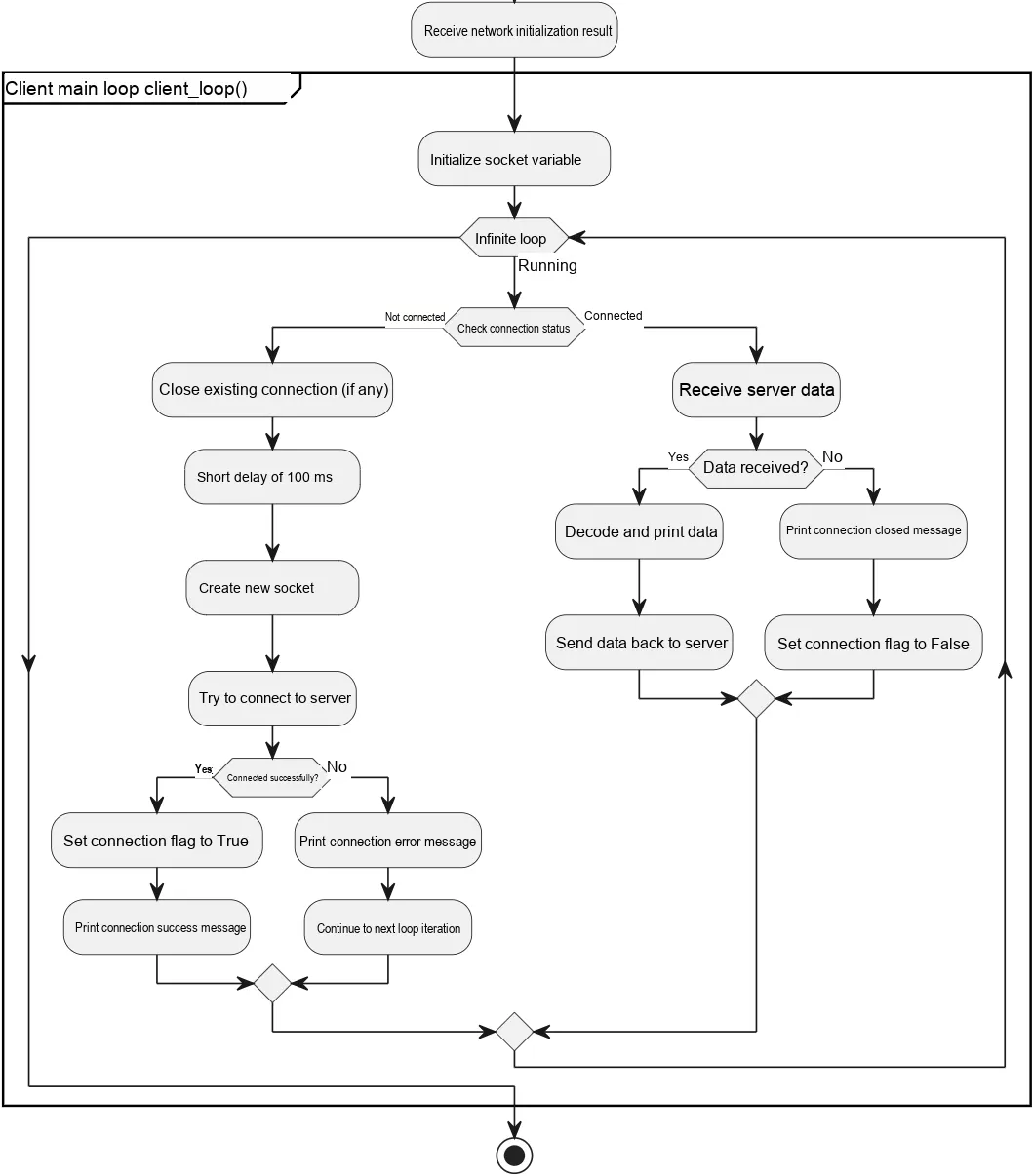
- Initialize the socket variable and enter an infinite loop;
- If there is no current connection (
conn_flagisFalse):- If a socket already exists, close it, and create a new socket object after a 100ms delay;
- Attempting to connect to the server:
- If the connection succeeds, set
conn_flagtoTrueand output the connection information - If the connection fails, an error message will be output and
conn_flagwill be kept asFalse;
- If the connection succeeds, set
- If already connected (
conn_flagisTrueand the socket is valid):- Attempt to receive data; if data is received, decode it into a string and output it, meanwhile send a postback of the data;
- If empty data is received (indicating that the server has closed the connection) or an exception occurs, output the corresponding information and set
conn_flagtoFalse.
Then we launch the NetAssist software, select the protocol type as TCP Server, configure the local host address to 198.168.1.6, which can be queried by entering the ipconfig command in the terminal. Set the local host port to be consistent with that in the code, which is 8080, keep all other options as default, and click the " Open " button:
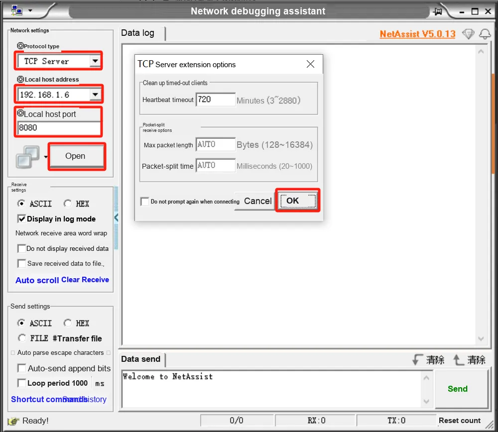
At this point, the lower-left corner of the software displays the " Ready " message:
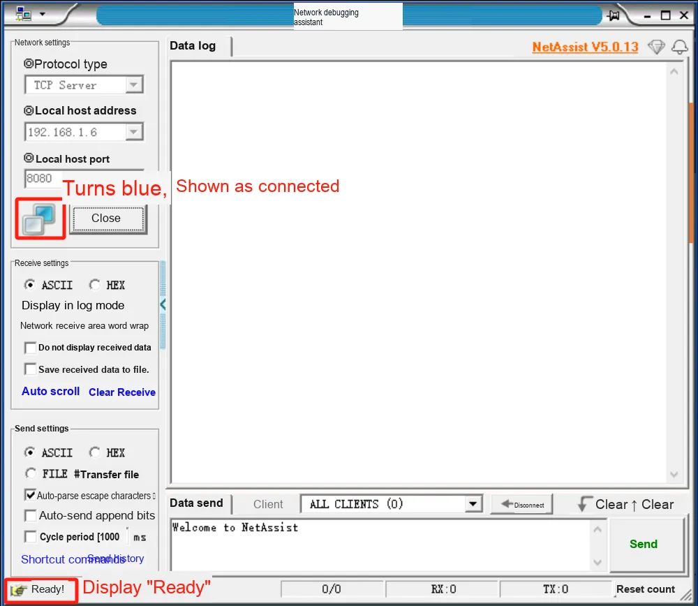
3.1.2 TCP Client - NetAssitant Configuration.mp4 2.1 MB
Burn the code and connect to the remote terminal:
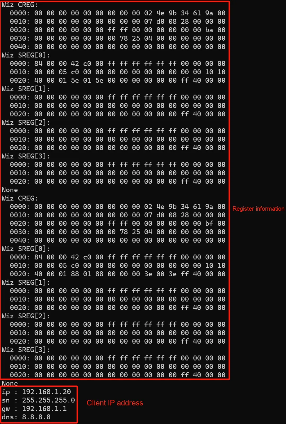

As can be seen, TCP Client and the server have both completed the connection.
Next, we send data to the Client via the server:
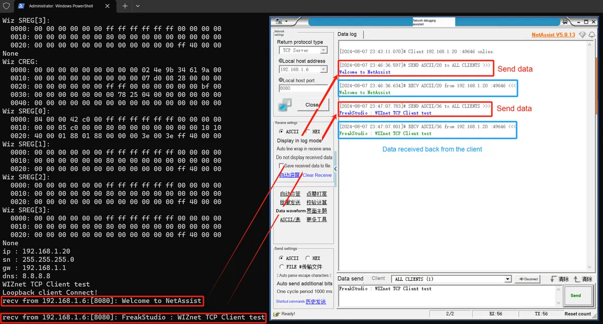
3.1.2 TCP Client Application Experiment.mp4 2.9 MB
As can be seen, the data received by the Client is posted back to the server again.
3.1.3 TCP Server Experiment
In this experiment, we will configure the W5500 and Raspberry Pi Pico as a server for the TCP protocol, and its basic workflow is as follows: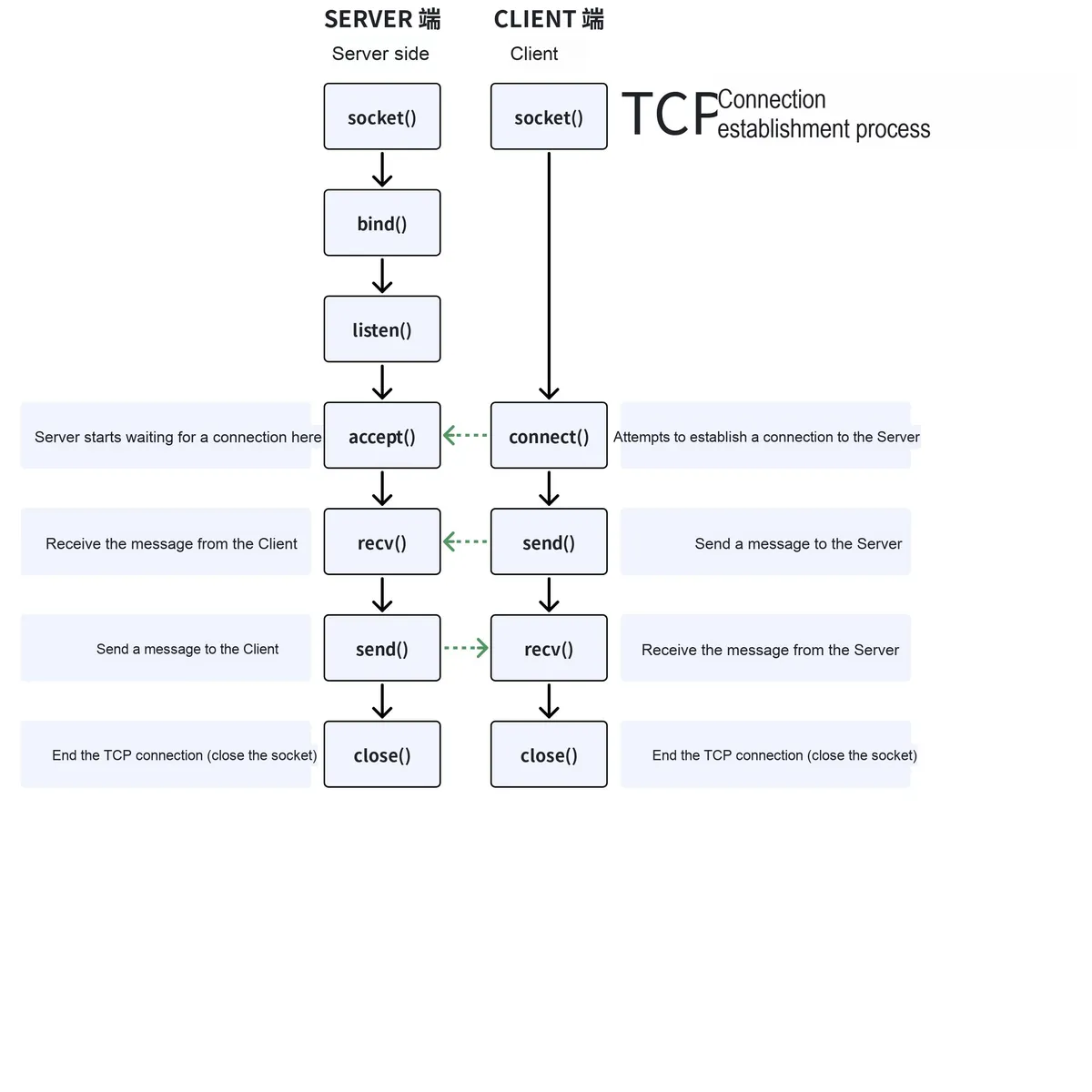
- Listening Port: The server creates a socket, binds it to a specified IP Address and port, and listens for connection requests from the Client;
- Establishing a connection: When a Client initiates a connection request, the server accepts the connection and creates a new socket (child socket) for each Client to handle communication with that Client;
- Data Interaction: The server and Client transmit data through sub-sockets, and usually perform read and write operations via ByteFlow;
- Close the connection: After data transmission is completed, both parties can close the child socket and continue listening for connection requests from other Clients.
The following code can be found in the material package we provide, in the elegance-devkit v1\Demo\42 ETH_TCP_Server folder.
The sample code is as follows:
# Python env   : MicroPython v1.23.0 on Wiznet W5500
# -*- coding: utf-8 -*-
# @Time    : 2024/8/8 11:08 AM
# @Author  : Li Qingshui
# @File    : main.py
# @Description : Ethernet experiment, TCP server test

# ======================================== Import Modules ========================================

# Import the socket module used to create and manage network connections
from usocket import socket
# Import hardware-related modules
from machine import Pin,SPI
# Import time-related modules
import time
# Import network-related modules
import network

# ======================================== Global Variables ============================================

# TCP server IP address
ip = '192.168.1.20'
sn = '255.255.255.0'
gw = '192.168.1.1'
dns= '8.8.8.8'
# Tuple object used for the network connection
netinfo=(ip, sn, gw, dns)

# Local listening address and port
localip = '192.168.1.20'
localport = 8000
# Tuple object used for the network connection
listen_info = (localip, localport)

# Global variable indicating the connection state
conn_flag = False

# ======================================== Functions ============================================

# Initialize the network interface
def w5x00_init() -> network.WIZNET5K:
    """
    Initialize a network.WIZNET5K instance, set a static IP address, and connect to the network.

    Args:
        None

    Returns:
        network.WIZNET5K: The network.WIZNET5K instance that was initialized and connected successfully.

    Raises:
        None
    """

    # Declare global variables
    global localip

    # Initialize the SPI object
    spi = SPI(0, 2_000_000, mosi=Pin(19), miso=Pin(16), sck=Pin(18))
    # Instantiate the network.WIZNET5K class, passing in the chip select pin CS and reset pin RST
    nic = network.WIZNET5K(spi, Pin(17), Pin(20))
    # Activate the network interface
    nic.active(True)
    # Set the static IP address: host address, subnet mask, gateway address, and DNS server address
    nic.ifconfig(netinfo)

    # Loop while the network is not connected
    while not nic.isconnected():
        time.sleep(1)
        # Output register information
        print(nic.regs())

    # Print the configured IP address
    print('ip :', nic.ifconfig()[0])
    print('sn :', nic.ifconfig()[1])
    print('gw :', nic.ifconfig()[2])
    print('dns:', nic.ifconfig()[3])

    # Return the network.WIZNET5K instance
    return nic

def server_loop() -> None:
    """
    Server main loop, used to accept client connections and handle data.

    This function keeps running and waits for client connections. Once a client connects successfully, the server receives the data sent by the client,
    and sends the data back to the client. If the connection is lost, the server goes back to waiting for a connection.

    Args:
        None

    Returns:
        None

    Raises:
        None
    """

    # Declare global variables
    global localip
    global conn_flag

    # Infinite loop to keep the server running
    while True:
        # If there is no connection currently, wait for a client to connect
        if (conn_flag == False):
            # Create a socket object
            s = socket()
            # Bind the socket to the local IP address and port
            s.bind(listen_info)
            # Start listening for connection requests, with a maximum connection queue length of 5
            s.listen(5)
            # Set the connection state to connected
            conn_flag = True
            # Output test information
            print("TEST server Loop")
            # Print the server IP and listening port information
            print('TCP Server:{0} ,listen port:{1}\r\n'.format(localip, listen_info[1]))
            # Accept a client connection; this blocks until a client connects before the next statement runs
            conn, addr = s.accept()
            # Print the IP and port of the connected client
            print('Connect from {0}:{1}\r\n'.format(addr[0], addr[1]))
        else:
            # If there is already a connection
            try:
                # Try to receive up to 2048 bytes of data
                data = conn.recv(2048)
                # Decode the received data into a string
                data = data.decode('utf-8')
                # Print the received data
                print(data)

                # If the received data is not 'NULL'
                if data != 'NULL':
                    # Encode the data into bytes and send it back
                    conn.send(data)
            # If an error occurs while receiving or sending data, an exception is raised and the following code block runs
            except:
                # Output the disconnection information
                print('disconnect')
                # Set the connection flag to False, indicating the connection has been lost
                # Continue to the code block that waits for a client connection
                conn_flag = False

# ======================================== Custom Classes ============================================

# ======================================== Initialization ==========================================

# Delay 3 s, wait for the device to power up
time.sleep(3)
# Print debug information
print("FreakStudio : Using W5x00 Ethernet to do TCP Server Test")

# Initialize the w5500 module
nic = w5x00_init()

# ========================================  Main Program  ===========================================

# Run the client loop
server_loop()
Here, the TCP server address we use is 192.168.1.20. In the server loop function server_loop, we perform the following operations: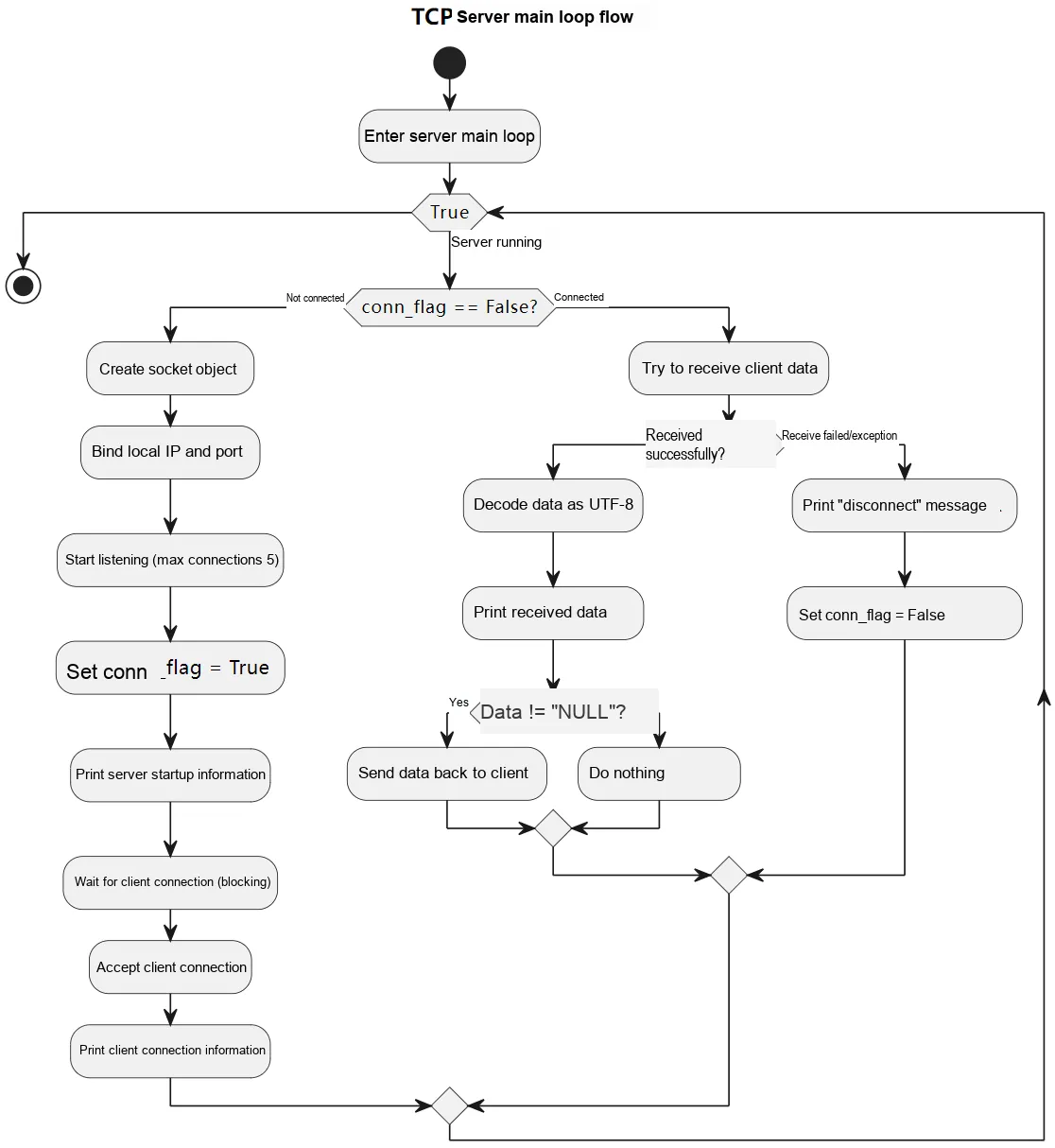
- If there is no current connection, create a socket object, bind the IP Address and port, and start listening for connection requests
- Print the IP and port information of the server, and wait for Client connections
- Print connection information after accepting a Client connection
- If a connection already exists, attempt to receive and process the data sent by the Client
- If the data is not empty, send it back to the Client
- Handle exceptions that occur during data reception or transmission, print disconnection information, and set the connection flag to False
Burn the code and open the remote terminal:

You can see that the TCP server address and Port Number are output, the accept () method functions to block execution until a Client connects to the server:
- When the server is waiting for a Client to connect, the program will pause at
s.accept ()this line, ensuring that the server can correctly receive and process connection requests from each Client - Once a Client connection request comes in,
the accept ()method will return a new socket objectconnand the Client addressaddr
We launch the NetAssist software, select the protocol type as TCP Client, set the remote host address to 198.168.1.20, configure the remote host port to be consistent with that in the code, which is 8000, keep all other options as default, and then click the "Connect" button:
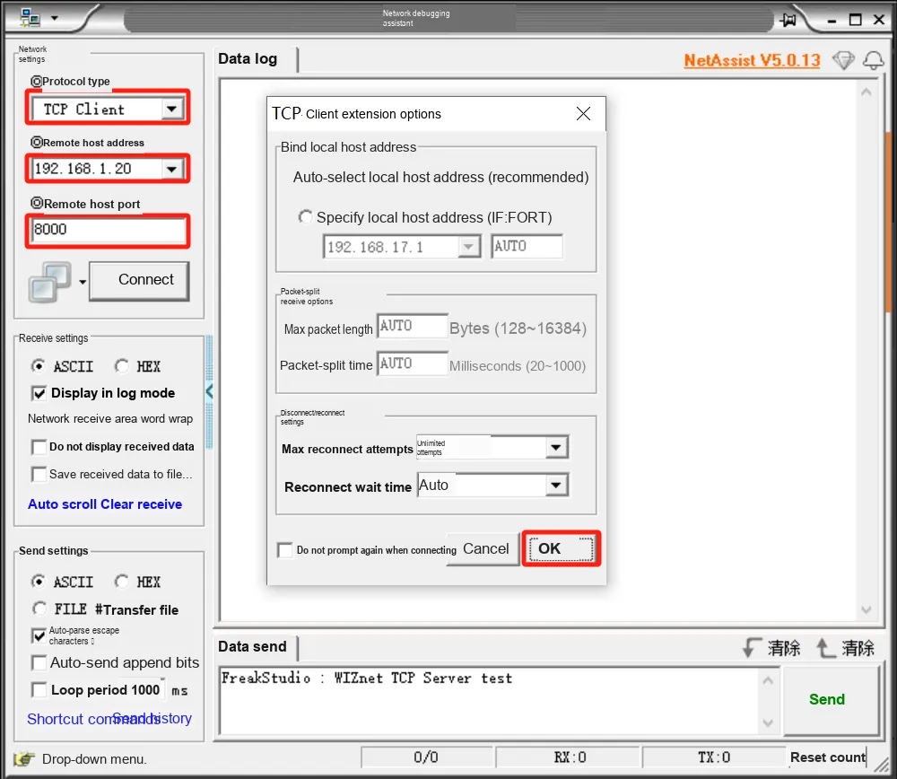
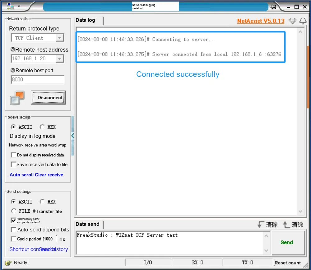
We can see the connection success message displayed in the terminal:
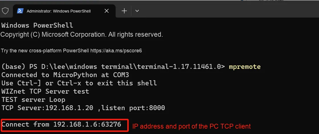
We send data via the NetAssist software, and we can see that the corresponding data is posted back to the TCP Client:
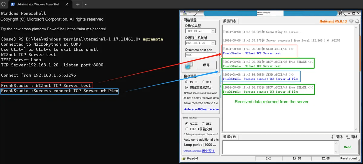
3.1.2 TCP Server.mp4 3.8 MB
3.2 UDP Protocol Experiment
UDP is a connectionless transport layer protocol, which is suitable for applications that require fast and simple data transmission without establishing and maintaining connections. It can send data without pre-establishing a connection, and each datagram is transmitted independently without the need to set up and sustain connection states.
The workflow of communicating using the UDP protocol is as follows:
- Create
UDPsocket: Each device (host) first needs to create aUDPsocket; - Binding to a Port: Each
UDPsocket is bound to a specific Port Number, which acts like a unique house number on the host, enabling incoming data packets to locate the correct application; - Sending data : When the host needs to send data, it passes the data to the
UDPprotocol, which adds aUDPheader in front of the data and then sends the data (now called "datagrams") to the network; - Receive data: At the receiving end, the datagram is routed to the correct host and port, and then delivered to the corresponding application.
The following code can be found in the elegance-devkit v1\Demo\43 ETH_UDP folder in the resource package we provide.
Next, we will conduct the UDP experiment, in which we use MicroPython on the Raspberry Pi Pico to control the Wiznet W5500 Ethernet module to listen for UDP data packets, and return the received data to the sender as-is. The sample code is as follows:
# Python env   : MicroPython v1.23.0 on Wiznet W5500
# -*- coding: utf-8 -*-
# @Time    : 2024/8/8 2:28 PM
# @Author  : Li Qingshui
# @File    : main.py
# @Description : Ethernet experiment, UDP protocol test

# ======================================== Import Modules ========================================

# Import the socket module used to create and manage network connections
from usocket import socket, AF_INET, SOCK_DGRAM
# Import hardware-related modules
from machine import Pin,SPI
# Import time-related modules
import time
# Import network-related modules
import network

# ======================================== Global Variables ============================================

# Device IP address
ip = '192.168.1.20'
sn = '255.255.255.0'
gw = '192.168.1.1'
dns= '8.8.8.8'

# Tuple object used for the network connection
netinfo=(ip, sn, gw, dns)
# Listening port
localport = 8000

# ======================================== Functions ============================================

# Initialize the network interface
def w5x00_init() -> network.WIZNET5K:
    """
    Initialize a network.WIZNET5K instance, set a static IP address, and connect to the network.

    Args:
        None

    Returns:
        network.WIZNET5K: The network.WIZNET5K instance that was initialized and connected successfully.

    Raises:
        None
    """

    # Declare global variables
    global localport

    # Initialize the SPI object
    spi = SPI(0, 2_000_000, mosi=Pin(19), miso=Pin(16), sck=Pin(18))
    # Instantiate the network.WIZNET5K class, passing in the chip select pin CS and reset pin RST
    nic = network.WIZNET5K(spi, Pin(17), Pin(20))
    # Activate the network interface
    nic.active(True)
    # Set the static IP address: host address, subnet mask, gateway address, and DNS server address
    nic.ifconfig(netinfo)

    # Loop while the network is not connected
    while not nic.isconnected():
        time.sleep(1)
        # Output register information
        print(nic.regs())

    # Print the configured IP address
    print('ip :', nic.ifconfig()[0])
    print('sn :', nic.ifconfig()[1])
    print('gw :', nic.ifconfig()[2])
    print('dns:', nic.ifconfig()[3])

    # Return the network.WIZNET5K instance
    return nic

def udp_loop(nic: 'network.WIZNET5K') -> None:
    """
    UDP listening loop, receives and prints UDP packets.

    Args:
        nic (network.WIZNET5K): network.WIZNET5K instance, used to get the network interface configuration.

    Returns:
        None: This function has no return value.

    Raises:
        None: This function does not raise exceptions.
    """

    # Declare global variables
    global localport

    # Create a UDP socket
    # AF_INET is a kind of address family, meaning the IPv4 protocol family is used
    # SOCK_DGRAM is a kind of socket type, meaning the UDP protocol is used
    s = socket(AF_INET, SOCK_DGRAM)
    # Bind the socket to the specified IP address and port
    s.bind((nic.ifconfig()[0], localport))
    # Print the information about opening the UDP listening loop, including the IP address and port
    print(f"Opened UDP loopback\r\nip:{nic.ifconfig()[0]},port:{localport}")

    # Wait 1 second to make sure the socket is ready
    time.sleep(1)

    # Infinite loop to keep listening for UDP packets
    while True:
        # Receive a packet of up to 2048 bytes, returning the data and the sender's address
        # This is a blocking call: when there is no data to receive, the program waits here until data arrives
        data, addr = s.recvfrom(2048)
        # Print the received data and the sender's address
        print(f'Received:{data} from:{addr}')
        # Send the received data back to the sender
        s.sendto(b'%s' % data, addr)

# ======================================== Custom Classes ============================================

# ======================================== Initialization ==========================================

# Delay 3 s, wait for the device to power up
time.sleep(3)
# Print debug information
print("FreakStudio : Using W5x00 Ethernet to do UDP Connect Test")

# Initialize the w5500 module
nic = w5x00_init()

# ========================================  Main Program  ===========================================

# Run the UDP loop
udp_loop(nic)
In the UDP server main loop (udp_loop () function), we perform the following operations: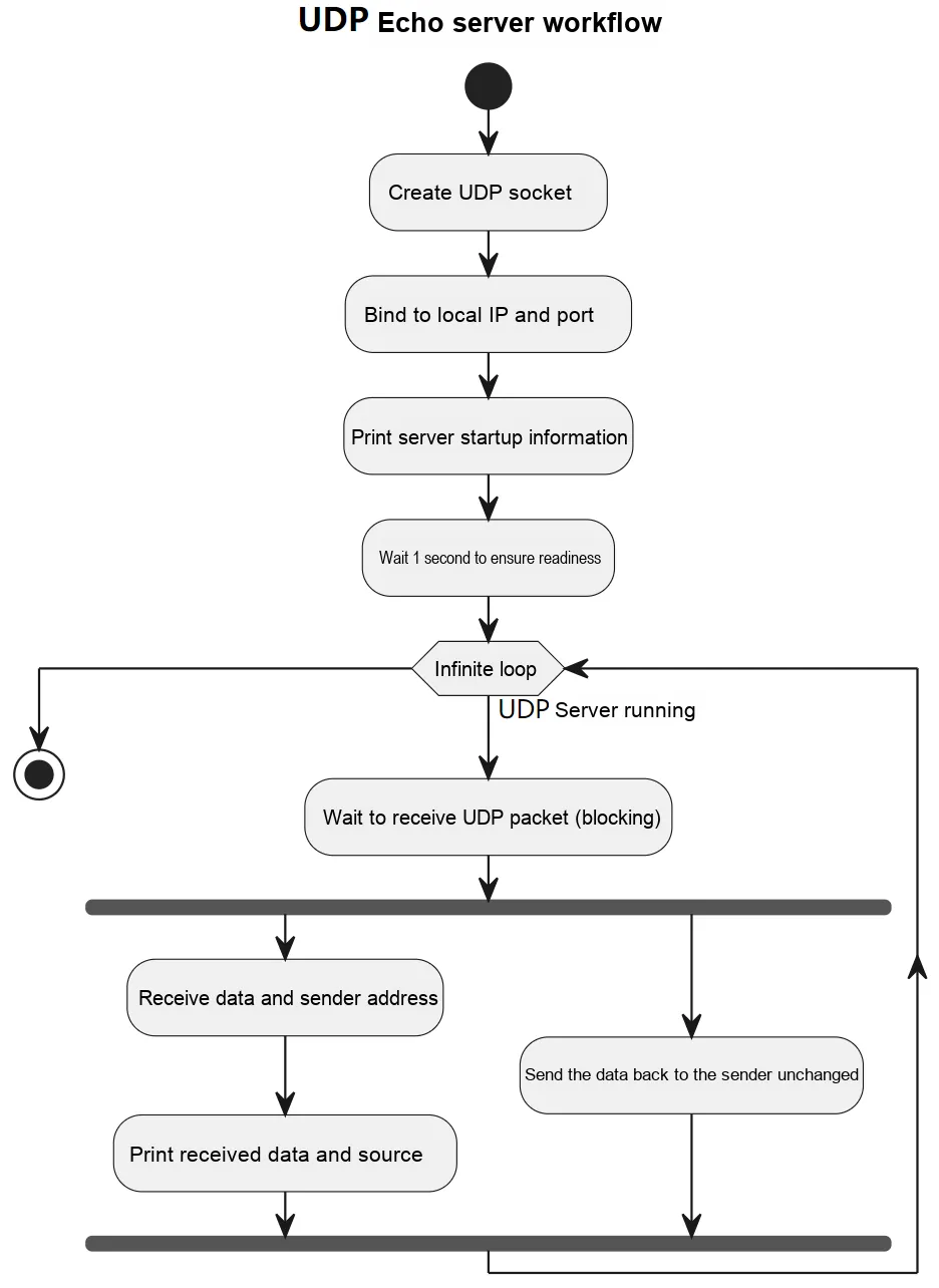
- Create
a UDPsocket: use theIPv4address family (AF_INET) and theUDPprotocol (SOCK_DGRAM); - Bind the socket: bind the socket to
W5500'sIPAddress and the specified port; - Print listening information: output the currently listening
IPAddress and Port Number; - Waiting for data packets: In an infinite loop, block and wait to receive UDP data packets (
recvfrom); - Print and postback data: After receiving the data, print the sender's address and the data content, then send the data back to the sender via (
sendto).
It should be noted that during the UDP listening process, there is no need to pre-specify the sender's IP Address and port. A UDP server only needs to bind its own local IP Address and Port Number to listen for and receive data packets from any sender, and obtain the address information of the sending device via the recvfrom () function.
Burn the code, open the terminal, and you can see the following information displayed:
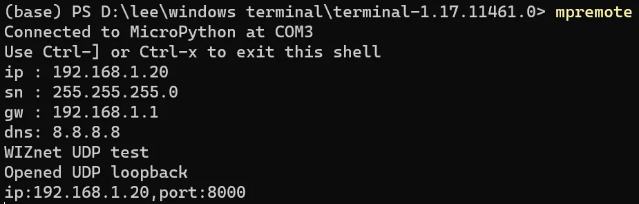
We open the NetAssist software, select the protocol type as UDP, configure the remote and local address to the computer's address (198.168.1.6), keep the local host port as default, which is 8080, leave all other options as default, and click the " Open " button:
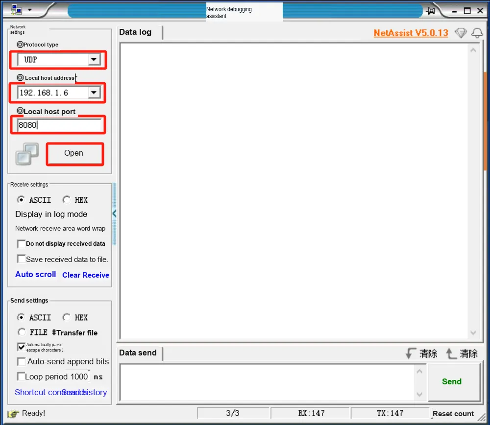
Input data, and you can see that the Pico and w5500 modules normally receive and postback the relevant data.
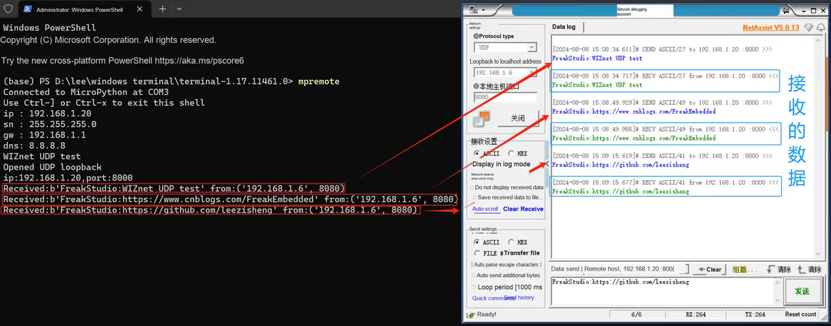
3.2 UDP Application Experiment.mp4 5.4 MB
3.3 DHCP Protocol Experiment
DHCP can automatically assign a new IP Address to devices, eliminating the need for users to manually modify configurations. In the following code, we attempt to dynamically obtain an IP Address via DHCP:
- If
DHCPacquisition succeeds, use the dynamically assigned network configuration - If
DHCPacquisition fails, use the statically configured network parameters
Wait for the network connection to succeed, then output the obtained network configuration information.
The following code can be found in the material package we provide elegance-devkit v1\Demo\44 ETH_DHCP folder.
Note that when conducting the DHCP protocol experiment, you need to connect the Ethernet port of the W5500 module to a router for normal operation.
The sample code is as follows:
# Python env   : MicroPython v1.23.0 on Wiznet W5500
# -*- coding: utf-8 -*-
# @Time    : 2024/8/8 3:23 PM
# @Author  : Li Qingshui
# @File    : main.py
# @Description : Ethernet experiment, DHCP protocol test

# ======================================== Import Modules ========================================

# Import the socket module used to create and manage network connections
from usocket import socket
# Import hardware-related modules
from machine import Pin,SPI
# Import time-related modules
import time
# Import network-related modules
import network

# ======================================== Global Variables ============================================

# Device IP address
ip = '192.168.1.20'
sn = '255.255.255.0'
gw = '192.168.1.1'
dns= '8.8.8.8'
# Tuple object used for the network connection
netinfo=(ip, sn, gw, dns)

# ======================================== Functions ============================================

# Initialize the network interface
def w5x00_init() -> 'network.WIZNET5K':
    """
    Initialize a network.WIZNET5K instance, set a static IP address, and connect.

    Returns:
        network.WIZNET5K: The network.WIZNET5K instance that was initialized and connected successfully.

    Raises:
        None: This function does not raise exceptions, but falls back to the static configuration when DHCP fails.
    """

    # Declare global variables
    global netinfo

    # Initialize the SPI object
    spi = SPI(0, 2_000_000, mosi=Pin(19), miso=Pin(16), sck=Pin(18))
    # Instantiate the network.WIZNET5K class, passing in the chip select pin CS and reset pin RST
    nic = network.WIZNET5K(spi, Pin(17), Pin(20))
    # Activate the network interface
    nic.active(True)

    try:
        print("\r\nConfiguring DHCP")
        # Try to use DHCP to dynamically obtain network configuration such as IP address, subnet mask, gateway and DNS server
        nic.ifconfig('dhcp')
    except:
        print("\r\nDHCP fails, use static configuration")
        # If DHCP fails, use the static IP address configuration
        nic.ifconfig(netinfo)

    # Loop while the network is not connected
    while not nic.isconnected():
        time.sleep(1)
        # Output register information
        print(nic.regs())

    # Print the configured IP address
    print('ip :', nic.ifconfig()[0])
    print('sn :', nic.ifconfig()[1])
    print('gw :', nic.ifconfig()[2])
    print('dns:', nic.ifconfig()[3])

    # Return the network.WIZNET5K instance
    return nic

# ======================================== Custom Classes ============================================

# ======================================== Initialization ==========================================

# Delay 3 s, wait for the device to power up
time.sleep(3)
# Print debug information
print("FreakStudio : Using W5x00 Ethernet to do DHCP test")

# Initialize the w5500 module
nic = w5x00_init()

# ========================================  Main Program  ===========================================

# The main loop idles and waits
while True:
    time.sleep(1)
Burn the code, open the terminal, and we can see the following input:
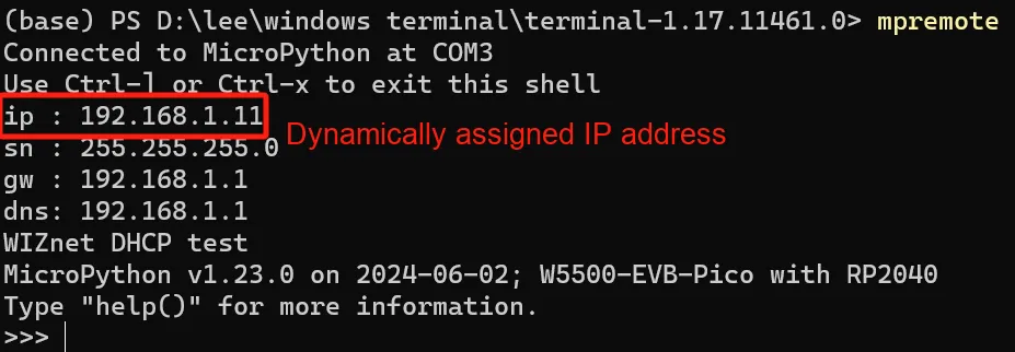
3.3 DHCP Experiment.mp4 780 KB
As we can see, the host IP Address assigned to us is 192.168.1.11, and we will try to run a ping test on this address:
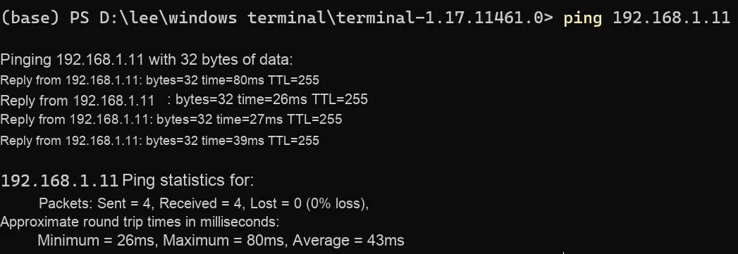
ping test succeeded, and the dynamically assigned IP Address provided to us is available.
3.4 DNS Protocol Experiment
The following code can be found in the elegance-devkit v1\Demo\45 ETH_DNS folder of the resource package we provide.
Note that when conducting DNS protocol experiments, you need to connect the Ethernet port of the W5500 module to a router for normal operation.
The DNS protocol can convert human-memorable domain names (such as www.example.com) into IP addresses recognizable by computers (such as 192.168.1.100). Next, we will use the WIZnet W5500 Ethernet module to perform a DNS query in the MicroPython environment, so as to convert the entered domain name into an IP address. The sample code is as follows:
# Python env   : MicroPython v1.23.0 on Wiznet W5500
# -*- coding: utf-8 -*-
# @Time    : 2024/8/8 3:47 PM
# @Author  : Li Qingshui
# @File    : main.py
# @Description : Ethernet experiment, DNS protocol test

# ======================================== Import Modules ========================================

# Import the socket module used to create and manage network connections
from usocket import socket,getaddrinfo,SOCK_STREAM
# Import hardware-related modules
from machine import Pin,SPI
# Import time-related modules
import time
# Import network-related modules
import network

# ======================================== Global Variables ============================================

# Device IP address
ip = '192.168.1.20'
sn = '255.255.255.0'
gw = '192.168.1.1'
dns= '8.8.8.8'

# Tuple object used for the network connection
netinfo=(ip, sn, gw, dns)

# Domain name to query: the cnblogs address
domain = "www.cnblogs.com"

# ======================================== Functions ============================================

# Function to initialize the network interface
def w5x00_init() -> 'network.WIZNET5K':
    """
    Initialize a network.WIZNET5K instance, set a static IP address, and connect.

    Returns:
        network.WIZNET5K: The network.WIZNET5K instance that was initialized and connected successfully.

    Raises:
        None: This function does not raise exceptions.
    """

    # Declare global variables
    global netinfo

    # Initialize the SPI object
    spi = SPI(0, 2_000_000, mosi=Pin(19), miso=Pin(16), sck=Pin(18))
    # Instantiate the network.WIZNET5K class, passing in the chip select pin CS and reset pin RST
    nic = network.WIZNET5K(spi, Pin(17), Pin(20))
    # Activate the network interface
    nic.active(True)

    try:
        print("\r\nConfiguring DHCP")
        # Try to use DHCP to dynamically obtain network configuration such as IP address, subnet mask, gateway and DNS server
        nic.ifconfig('dhcp')
    except:
        print("\r\nDHCP fails, use static configuration")
        # If DHCP fails, use the static IP address configuration
        nic.ifconfig(netinfo)

    # Loop while the network is not connected
    while not nic.isconnected():
        time.sleep(1)
        # Output register information
        print(nic.regs())

    # Print the configured IP address
    print('ip :', nic.ifconfig()[0])
    print('sn :', nic.ifconfig()[1])
    print('gw :', nic.ifconfig()[2])
    print('dns:', nic.ifconfig()[3])

    # Return the network.WIZNET5K instance
    return nic

def dns_query(domain: str) -> str:
    """
    DNS query function, used to get the IP address corresponding to a domain name.

    Args:
        domain (str): The domain name to query.

    Returns:
        str: The IP address corresponding to the domain name.

    Raises:
        None: This function does not raise exceptions.
    """
    # Get the IP address corresponding to the domain name through a DNS query
    # 80 is the port number used, 0 means the default IPv4 address family is used
    # SOCK_STREAM means a TCP socket is used for data transmission
    ip = getaddrinfo(domain, 80,0, SOCK_STREAM)
    # Return the IP address part of the query result
    return ip[0][4][0]

# ======================================== Custom Classes ============================================

# ======================================== Initialization ==========================================

# Delay 3 s, wait for the device to power up
time.sleep(3)
# Print debug information
print("FreakStudio : Using W5x00 Ethernet to do DNS query")

# Initialize the w5500 module
nic = w5x00_init()

# ========================================  Main Program  ===========================================

# Query the IP address corresponding to the domain name through DNS
ip = dns_query(domain)
# Print the query result
print("IP address of %s is %s"%(domain,ip))
Here, we define the domain name to be queried and call the dns_query () function to perform DNS resolution, obtain the IP address, and print the domain name and its corresponding IP address. In the dns_query () function, we call the getaddrinfo () method to resolve the domain name and obtain the associated IP address information, specifying the Port Number, address family type and socket type for resolution.
The domain name we resolve is that of Cnblogs (Cnblogs): " www.cnblogs.com ". Cnblogs is a community-based article sharing platform for developers, where users can share their programming experience, technical insights and other content to help other developers.
Burn the code, open the terminal, and you will see the following output:
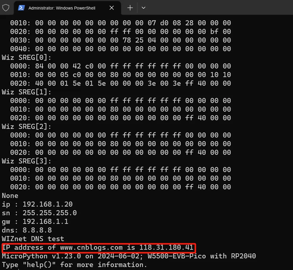
As can be seen, the resolved IP Address corresponding to the domain name of CNBlogs is: 118.31.180.41.
3.4 DNS Protocol Experiment.mp4 2.3 MB
We can verify this on an IP lookup website, and the IP lookup URL we use here is:
https://site.ip138.com/www.cnblogs.com/
Verification successful. 118.31.180.41 is the IP address of the Hangzhou Alibaba Cloud server of CNBlogs.
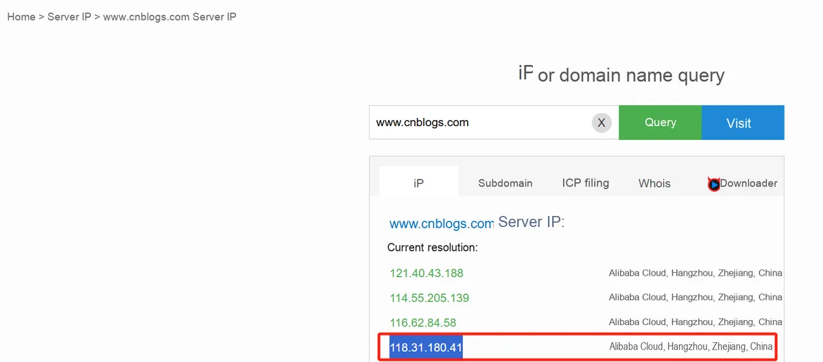
Here, if the following error is thrown:
>>> ip = getaddrinfo(domain, 80,0, SOCK_STREAM)
Traceback (most recent call last):
  File "<stdin>", line 1, in <module>
OSError: -2
Usually related to DNS server unavailability, the DNS server 8.8.8.8 (Google DNS) in use may be restricted in China, leading to resolution failure. We can switch to the following DNS servers:
1.1.1.1 (Cloudflare DNS)
The router's IP address (usually also the DNS server)
223.5.5.5 (Alibaba Cloud public DNS server)
114.114.114.114 (public DNS server provided by domestic carriers in China)
3.5 HTTP Protocol Experiment
3.5.1 HTTP Client Experiment
Here, we use http://httpbin.org as a test HTTP request and response service, which provides test endpoints for various HTTP methods (GET, POST, PUT, DELETE, etc.), allowing developers to quickly test their HTTP Client code here.
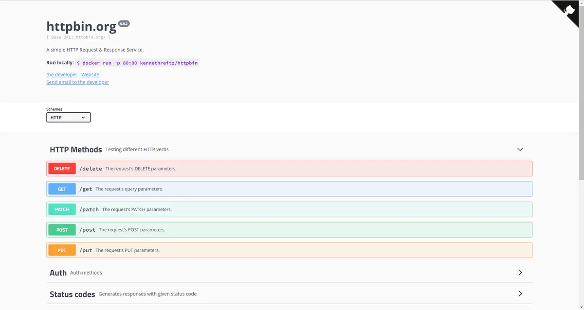
Its main functions include:
- Test GET Request: A function that allows you to send a GET request and view the data returned by the server
- Test POST Request: Send a POST request, upload data and check the response
- View Request Headers: You can view the request headers sent by the Client
- Simulated Delay: You can set the corresponding delay time to test the performance of the Client when the network is unstable
- Test File Upload: Supports uploading files and viewing the file information received by the server
- Simulate various HTTP status codes: It can return the specified HTTP status codes, facilitating the testing of how the Client handles different status codes
The following code can be found in the material package we provide elegance-devkit v1\Demo\46 ETH_HTTP_Client folder.
Note that when conducting HTTP Client experiments, you need to connect the Ethernet port of the W5500 module to a router for normal operation.
Here, we use the Http protocol to execute HTTP GET and POST requests, and print the status code and response data of the requests. The sample code is shown below:
# Python env   : MicroPython v1.23.0 on Wiznet W5500
# -*- coding: utf-8 -*-
# @Time    : 2024/8/8 8:14 PM
# @Author  : Li Qingshui
# @File    : main.py
# @Description : Ethernet experiment, HTTP client test

# ======================================== Import Modules ========================================

# Import HTTP request-related modules
import urequests
# Import hardware-related modules
from machine import Pin,SPI
# Import time-related modules
import time
# Import network-related modules
import network

# ======================================== Global Variables ============================================

# Device IP address
ip = '192.168.1.20'
sn = '255.255.255.0'
gw = '192.168.1.1'
dns= '8.8.8.8'
# Tuple object used for the network connection
netinfo=(ip, sn, gw, dns)

# Define the URL for the GET request
geturl = "http://httpbin.org/get"
# Define the URL for the POST request
posturl = "http://httpbin.org/post"

# ======================================== Functions ============================================

# Function to initialize the network connection
def w5x00_init() -> 'network.WIZNET5K':
    """
    Initialize a network.WIZNET5K instance, set a static IP address, and connect.

    Returns:
        network.WIZNET5K: The network.WIZNET5K instance that was initialized and connected successfully.

    Raises:
        None: This function does not raise exceptions.
    """

    # Declare global variables
    global netinfo

    # Initialize the SPI object
    spi = SPI(0, 2_000_000, mosi=Pin(19), miso=Pin(16), sck=Pin(18))
    # Instantiate the network.WIZNET5K class, passing in the chip select pin CS and reset pin RST
    nic = network.WIZNET5K(spi, Pin(17), Pin(20))
    # Activate the network interface
    nic.active(True)

    try:
        print("\r\nConfiguring DHCP")
        # Try to use DHCP to dynamically obtain network configuration such as IP address, subnet mask, gateway and DNS server
        nic.ifconfig('dhcp')
    except:
        print("\r\nDHCP fails, use static configuration")
        # If DHCP fails, use the static IP address configuration
        nic.ifconfig(netinfo)

    # Loop while the network is not connected
    while not nic.isconnected():
        time.sleep(1)
        # Output register information
        print(nic.regs())

    # Print the configured IP address
    print('ip :', nic.ifconfig()[0])
    print('sn :', nic.ifconfig()[1])
    print('gw :', nic.ifconfig()[2])
    print('dns:', nic.ifconfig()[3])

    # Return the network.WIZNET5K instance
    return nic

# Function to send HTTP requests
def request() -> None:
    """
    Send HTTP requests, including GET and POST requests, and print the response results.

    Returns:
        None: This function has no return value.

    Raises:
        None: This function does not raise exceptions.
    """

    # Print a message indicating the start of the GET request test
    print("GET Request test")
    # Send a GET request with query parameters appended to the URL
    r = urequests.get(geturl + "?WIZnet=W5100S_W5500")

    # Print the response status code of the GET request
    print("Request response code:", r.status_code)
    # Print the value of the args field in the result returned by the GET request
    print("Request response args:", r.json()["args"])

    # Send a POST request with JSON data
    r = urequests.post(posturl, json={"WIZnet": "W5100S_W5500"})
    # If no response is received, print a message
    if not r:
        print('spreadsheet: no response received')

    # Print a message indicating the start of the POST request test
    print("\r\nPOST Request test")
    # Print the response status code of the POST request
    print("Request response code:", r.status_code)
    # Print the value of the data field in the POST response
    print("Request response data:", r.json()["data"])

# ======================================== Custom Classes ============================================

# ======================================== Initialization ==========================================

# Delay 3s, wait for the device to power up
time.sleep(3)
# Print debug information
print("FreakStudio : Using W5x00 Ethernet to do HTTP Client test")

# Initialize the w5500 module
nic = w5x00_init()

# ========================================  Main Program  ===========================================

# Call the request function to run the HTTP request test
request()
In the request function, we perform the following operations in sequence:
- Send a GET request to the specified URL via the
urequests.get ()method, and the GET request is used to retrieve data from the server:geturlis a predefined variable that represents the base URL to be requested."? WIZnet= W5100S_W5500"is a query string that will be appended to the end of a URL and passed to the server as a request parameter.- The result of the entire expression will be assigned to the variable
r, and thisrvariable is aResponseobject that contains the response information returned by the server, such as status code, response headers, and response body, etc. GETrequest query parameters will be received and parsed by the server, and are usually returned to theargsfield in the response to the Client
- Output
GETrequest status codes (e. g.,200indicates success,404indicates not found, etc.) to check whether the request succeeded and how the server responds to the request:- 200 (
OK): The request succeeded - 404 (
Not Found): Resource not found - 500 (
Internal Server Error): Internal Server Error
- 200 (
- Fetch and print the
argsfield in the JSON data returned by the server, and verify that the server has correctly received the query parameters and returned the expected data:r.json ()method is used to decode the JSON-formatted response body returned by the server into a Python dictionary.["args"]is used to retrieve the value corresponding to the "args" key from the decoded dictionary; in HTTP requests, "args" usually denotes query parameters.
- By using the
urequests.post ()method to send a POST request to the specified URL and pass JSON data containing Attribute–Value Pairs. POST requests are used to send data to the server, such as submitting forms or uploading files:posturl: The URL address to which the request is to be sentjson: Request data to be sent in JSON format{"WIZnet": "W5100S_W5500"}is a Python dictionary that represents the request data to be sent in JSON format- The result of sending the request will be assigned to the
Responseobjectr
- Check
POSTwhether the request is executed successfully. If no response from the server is received (i. e.risNone), print an error prompt message - Output
POSTthe status code of the request to check whether the request is successful, and whether the server has correctly received the request and returned a response - Retrieve and print the
datafield in the JSON data returned by the server to confirm that the server has correctly processed the sent data and returned the expected response:r.json ()method is used to decode the JSON-formatted response body returned by the server into a Python dictionary.["data"] is used to retrieve the value corresponding to the "data" key from the decoded dictionary- After receiving this POST request, the server will parse the JSON data in the request body and place it in the
datafield of the response to return it to the Client
To flash the code, open the terminal:
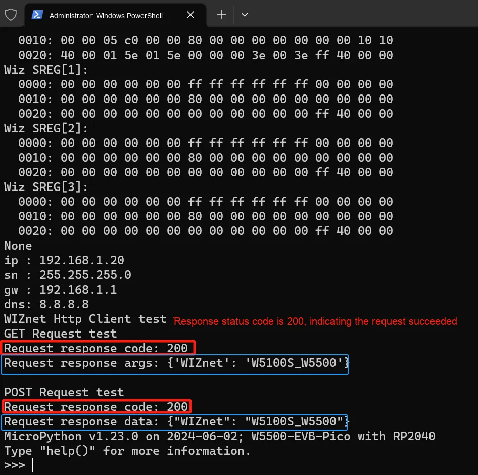
It can be seen that the response codes and submitted data content of the GET request and the POST request are printed respectively.
3.5.1 Application Experiment.mp4 2.9 MB
3.5.2 HTTP Server Experiment
When implementing an HTTP server with the Raspberry Pi Pico and w5500 module, the following steps are required:
- Establish connection:
WebBrowser (Client) andWebServer establish a virtual "socket" via aTCPconnection, which serves as the communication channel between the Client and the server.
- Send request:
- The Client sends through this socket
HTTPrequests, typically theGETorPOSTmethods GETrequests are used to retrieve resources,POSTrequests are used to submit data
- The Client sends through this socket
- Server Processing:
- After receiving a request, the server will, based on the request's
URL, locate and read the corresponding resource (such as anHTMLfile) - For
POSTrequests, the server will also parse the form data contained in the request body.
- After receiving a request, the server will, based on the request's
- Response returned:
- The server returns the resource data in the form of
HTTPresponse to the Client via a socket - The response contains
HTTPheader information and the actualHTMLfile content
- The server returns the resource data in the form of
- Close connection:
- After the data exchange is completed, the Client and the server will close this TCP connection
The following code can be found in the material package we provide, in the elegance-devkit v1\Demo\47 ETH_HTTP_Server folder.
In the following sample code, we build a simple HTTP server, and control the LED on the development board via a web page. The code is as follows:
# Python env   : MicroPython v1.23.0 on Wiznet W5500
# -*- coding: utf-8 -*-
# @Time    : 2024/8/8 PM 10:33
# @Author  : Li Qingshui
# @File    : main.py
# @Description : Ethernet experiment, HTTP server test

# ======================================== Import Modules ========================================

# Import hardware-related modules
from machine import Pin,SPI
# Import time-related modules
import time
# Import network-related modules
import network
# Import the socket module used to create and manage network connections
from usocket import socket

# ======================================== Global Variables ============================================

# Device IP address
ip = '192.168.1.20'
sn = '255.255.255.0'
gw = '192.168.1.1'
dns= '8.8.8.8'

# Tuple object used for the network connection
netinfo=(ip, sn, gw, dns)

# LED flag
on_flag = 0
off_flag = 0
blink_flag = 0

# ======================================== Functions ============================================

# Initialize the network connection
def w5x00_init() -> 'network.WIZNET5K':
    """
    Initialize a network.WIZNET5K instance, set a static IP address, and connect.

    Returns:
        network.WIZNET5K: The network.WIZNET5K instance that was initialized and connected successfully.

    Raises:
        None: This function does not raise exceptions.
    """

    # Declare global variables
    global netinfo

    # Initialize the SPI object
    spi = SPI(0, 2_000_000, mosi=Pin(19), miso=Pin(16), sck=Pin(18))
    # Instantiate the network.WIZNET5K class, passing in the chip select pin CS and reset pin RST
    nic = network.WIZNET5K(spi, Pin(17), Pin(20))
    # Activate the network interface
    nic.active(True)
    # If DHCP fails, use the static IP address configuration
    nic.ifconfig(netinfo)

    # Loop while the network is not connected
    while not nic.isconnected():
        time.sleep(1)
        # Output register information
        print(nic.regs())

    # Print the configured IP address
    print('ip :', nic.ifconfig()[0])
    print('sn :', nic.ifconfig()[1])
    print('gw :', nic.ifconfig()[2])
    print('dns:', nic.ifconfig()[3])

    # Return the network.WIZNET5K instance
    return nic

def web_page() -> str:
    """
    Generate the web page content, dynamically displaying content based on the LED state.

    Returns:
        str: The generated HTML web page content.

    Raises:
        None: This function does not raise exceptions.
    """

    # Declare the global variable led
    global led

    # Generate the corresponding text based on the LED state flag
    if on_flag == 1:
        led_state = "ON"
    elif off_flag == 1:
        led_state = "OFF"
    else:
        led_state = "BLINK"

    # Generate the HTML web page content, dynamically displaying content based on the LED state
    html = """
    <!DOCTYPE html>
    <html lang="en">
    <head>
    <meta charset="UTF-8">
    <meta http-equiv="X-UA-Compatible" content="IE=edge">
    <meta name="viewport" content="width=device-width, initial-scale=1.0">
    <title> Freak Studio Raspberry Pi Pico Web Server Test </title>
    <style>
        body {
            background-color: #2c3e50;
            color: #ecf0f1;
            font-family: Arial, sans-serif;
            text-align: center;
            margin-top: 50px;
        }
        h1 {
            color: #e74c3c;
            font-size: 3em;
        }
        h2 {
            color: #3498db;
            font-size: 2em;
        }
        .button {
            background-color: #27ae60;
            border: none;
            color: white;
            padding: 15px 32px;
            text-align: center;
            text-decoration: none;
            display: inline-block;
            font-size: 16px;
            margin: 4px 2px;
            cursor: pointer;
            border-radius: 12px;
            transition: background-color 0.3s ease;
        }
        .button:hover {
            background-color: #2ecc71;
        }
        .button2 {
            background-color: #e74c3c;
            border: none;
            color: white;
            padding: 15px 32px;
            text-align: center;
            text-decoration: none;
            display: inline-block;
            font-size: 16px;
            margin: 4px 2px;
            cursor: pointer;
            border-radius: 12px;
            transition: background-color 0.3s ease;
        }
        .button2:hover {
            background-color: #c0392b;
        }
        .button3 {
            background-color: #90448e;
            border: none;
            color: white;
            padding: 15px 32px;
            text-align: center;
            text-decoration: none;
            display: inline-block;
            font-size: 16px;
            margin: 4px 2px;
            cursor: pointer;
            border-radius: 12px;
            transition: background-color 0.3s ease;
        }
        .button3:hover {
            background-color: #c0392b;
        }
    </style>
    </head>
    <body>
    <div>
    <H1>Freak Studio Raspberry Pi Pico Web Server Test</H1>
    <h2>Control LED</h2>
    <p>PICO LED state: <strong>""" + led_state + """</strong></p>
    <p><a href="/?led=on"><button class="button">ON</button></a></p>
    <p><a href="/?led=off"><button class="button button2">OFF</button></a></p>
    <p><a href="/?led=blink"><button class="button button3">BLINK</button></a></p>
    </div>
    </body>
    </html>
    """

    # Return the generated HTML content
    return html

def web_server() -> None:
    """
    Run the web server, handle client requests and control the LED state.

    Returns:
        None: This function has no return value.

    Raises:
        None: This function does not raise exceptions.
    """

    # Declare the global variable ip
    global ip
    # Global variable for the LED state
    global on_flag, off_flag, blink_flag

    # Create a socket object
    s = socket()
    # Bind the IP address and port 80
    s.bind((ip, 80))
    # Listen for up to 5 client connections
    s.listen(5)

    while True:
        # Accept a client connection
        conn, addr = s.accept()
        # Print the client's IP address and port number
        print('Connect from %s' % str(addr))

        # Receive the client's request data, up to 1024 bytes
        request = conn.recv(1024)
        # Convert the request data to a string
        request = str(request)
        # Print the received request content
        print('Content = %s' % request)

        # Find the position of the LED on command in the request string
        led_on = request.find('/?led=on')
        # Find the position of the LED off command in the request string
        led_off = request.find('/?led=off')
        # Find the position of the LED blink command in the request string
        led_blink = request.find('/?led=blink')

        # If the on command is found, turn on the LED
        if led_on == 6:
            print("LED ON")
            led.value(1)

            on_flag = 1
            off_flag = 0
            blink_flag = 0

        # If the off command is found, turn off the LED
        if led_off == 6:
            print("LED OFF")
            led.value(0)

            on_flag = 0
            off_flag = 1
            blink_flag = 0

        # If the blink command is found, blink the LED
        if led_blink == 6:
            print("LED BLINK")
            for i in range(3):
                led.value(1)
                time.sleep(0.2)
                led.value(0)
                time.sleep(0.2)

            on_flag = 0
            off_flag = 0
            blink_flag = 1

        # Generate the HTML response content
        response = web_page()

        # Send the HTTP response headers
        conn.send('HTTP/1.1 200 OK\n')
        conn.send('Connection: close\n')
        conn.send('Content-Type: text/html\n')
        conn.send('Content-Length: %s\n\n' % len(response))

        # Send the HTML content
        conn.send(response)

        # Close the connection
        conn.close()

# ======================================== Custom Classes ============================================

# ======================================== Initialization ==========================================

# Delay 3s, wait for the device to power up
time.sleep(3)
# Print debug information
print("FreakStudio : Using W5x00 Ethernet to do HTTP Server test")

# Configure GPIO25 as an output pin to control the LED
led = Pin(25, Pin.OUT)
# Initialize the w5500 module
nic = w5x00_init()

# ========================================  Main Program  ===========================================

# Run the web server
web_server()
The basic workflow can be described as follows:
- Initialize the network interface: use the
w5x00_init ()function to initialize the network interface, set the IP Address and establish the connection; - Create a Web server: define the
web_server ()function, create a socket object and bind it to the IP Address and port 80, then listen for up to 5 Client connections; - Handle Client requests: In the
web_server ()function, accept Client connections, receive request data, and control the status of the LED according to the request content; - Generate web page content: use the
web_page ()function to generate web page content, and dynamically display the content according to theLEDstatus; - Send
HTTPResponse: Send the generatedHTMLcontent asHTTPresponse to the Client; - Close connection: After completing the Client request, close the connection with the Client.
In the web_page () function, we generate a HTML web page that allows users to control the LED status by clicking buttons. The web page provides three buttons: ON, OFF and BLINK, which are respectively used to control the on/off and blinking states of the LED. In the content section of the HTML web page, we have mainly completed the following work:
- Use a multi-line string (
""". ..""") to generate the HTML code for the web page HTMLcontent covers basic web page structures, such as the<!DOCTYPE html>declaration, the<html>,<head>and<body>tags- The page contains some
CSSstyles for beautifying web pages, including background colors, font styles, button styles, etc. - There are three main buttons, each of which is a
<a>tag that contains anhrefattribute, which is used to define the request path sent when the button is clicked:ONButton: Sends the/led= onrequest path when clickedOFFButton: Sends the/led= offrequest path when clickedBLINKButton: Sends the/led= blinkrequest path when clicked
When the user clicks these buttons, the Web server will receive the corresponding HTTP request, and operate the LED according to the request path, such as turning it on, off, or making the LED blink.
In web_server () function, we mainly perform the following operations:
- Create a server socket
s = socket (): Creates a socket object for network communication on the server sides.bind ((ip, 80)): Bind the IP Address and Port Number 80, indicating that the server will accept HTTP requests via this IP Address and ports.listen (5): Set the maximum number of Client connection requests that the server can accept to 5
- Enter the main loop and wait for Client connections
while True: The server enters an infinite loop, keeps running, and waits for Client connectionsconn, addr = s.accept (): The server waits for and accepts a Client connection,connrepresents the connection object,addris the Client's IP Address and Port Numberprint ('Connect from %s' % str (addr)): Print the IP Address and Port Number of the connecting Client
- Process Client requests
request = conn.recv (1024): Receive the HTTP request data sent by the Client, with a maximum of 1024 bytesrequest = str (request): Convert the request data into a string for subsequent processingprint ('Content = %s' % request): Print the received request content
- Parse and process LED control commands
led_on = request.find ('/? led= on'): Find the position of the LED turn-on command in the request stringled_off = request.find ('/? led= off'): Locate the position of the LED off commandled_blink = request.find ('/? led= blink'): Locate the position of the LED blink command
According to the request sent by the Client:
LED ON:- If the
LEDturn-on command (led_on == 6) is found, turn on the LED (led.value (1)); - Set
on_flagto 1, indicating that the LED is in the on state; meanwhile, setoff_flagandblink_flagto 0.
- If the
LED OFF:- If the
LEDturn-off command (led_off == 6) is found, turn off the LED (led.value (0)); - Set
off_flagto 1, indicating that the LED is in the off state; meanwhile, seton_flagandblink_flagto 0;
- If the
LED BLINK:- If the
LEDblinking command (led_blink == 6) is found, make the LED blink three times with an on-off interval of 0.2 seconds each time; - Set
blink_flagto 1, indicating that the LED is in a blinking state; meanwhile, seton_flagandoff_flagto 0;
- If the
- Generate and send
HTTPresponses:response = web_page (): call theweb_page ()function to generateLEDstatus-containingHTMLwebpage content;- Send HTTP response headers:
conn.send ('HTTP/1.1 200 OK\n'): Send the status line to indicate that the request has been processed successfully;conn.send ('Connection: close\n'): informs the Client to close the connection;conn.send ('Content-Type: text/html\n'): Specify the type of the response content as HTML;conn.send ('Content-Length: %s\n\n' % len (response)): Specify the length of the response content;
- Send HTML content:
conn.send (response): Send the generated HTML page;
- Close connection:
conn.close (): Close the connection with the Client and wait for the next Client request;
Wherein, the HTTP request includes the following contents:
Content = b'GET /favicon.ico HTTP/1.1\r\n
Host: 192.168.1.20\r\nConnection: keep-alive\r\n
User-Agent: Mozilla/5.0 (Windows NT 10.0; Win64; x64) AppleWebKit/537.36 (KHTML, like Gecko) Chrome/127.0.0.0 Safari/537.36 Edg/127.0.0.0\r\n
Accept: image/avif,image/webp,image/apng,image/svg+xml,image/*,*/*;q=0.8\r\n
Referer: http://192.168.1.20/?led=off\r\n
Accept-Encoding: gzip, deflate\r\n
Accept-Language: zh-CN,zh;q=0.9,en;q=0.8,en-GB;q=0.7,en-US;q=0.6\r\n\r\n'
The meaning of each part is as follows:
GET /favicon.ico HTTP/1.1: This is an HTTP GET request method used to request resources./favicon.icois the path of the requested resource; browsers usually request a website's favicon file to display it next to the address bar or tab title.HTTP/1.1specifies the HTTP protocol version used for the request.Host: 192.168.1.20: This line specifies the server's domain name or IP Address, which here is192.168.1.20;Connection: keep-alive: This line indicates that the Client wants to use a persistent connection (keep-alive), which allows multipleTCPconnections to be sent over the sameHTTPrequests, reducing the overhead of establishing and closing connections;User-Agent:Mozilla/5.0 (Windows NT 10.0; Win64; x64) AppleWebKit/537.36 (KHTML, like Gecko) Chrome/127.0.0.0 Safari/537.36 Edg/127.0.0.0: This is a user agent string that tells the server what Client initiated the request; here it is a user agent string simulating the Chrome browser;Accept:image/avif, image/webp, image/apng, image/svg+ xml, image/*, */*;q= 0.8: This line specifies the content types that the Client can receive and their respective priorities. In this example, the Client prioritizes images inAVIF,WebP, andAPNGformats, followed by all other image types with a quality factor of 0.8;Referer: http://192.168.1.20/? led= off : This line specifies the referring page of the request, i. e. the page from which the user linked to the page of the current request;Accept-Encoding:gzip, deflate: This line informs the server which content encodings the Client supports, so that the server can deliver compressed data to speed up transmission;Accept-Language:zh-CN, zh;q= 0.9, en;q= 0.8, en-GB;q= 0.7, en-US;q= 0.6: This line specifies the language types accepted by the Client and their priorities. In this example, the Client prefers Simplified Chinese (zh-CN) first, followed by various other English variants;
As you can see, in the code above we use the following command to determine whether to change the LED state:
# If the on command is found, turn on the LED
if led_on == 6:
    ...

# If the off command is found, turn off the LED
if led_off == 6:
    ...

# If the blink command is found, blink the LED
if led_blink == 6:
    ...
This is because the starting position index of substrings indicating the LED status, such as /? led= on in the request string, is exactly 6.
The overall work flow chart is shown as follows:
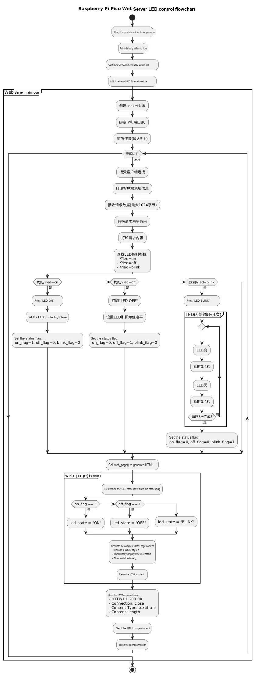
Burn the program, open the terminal, and you will see the following output:
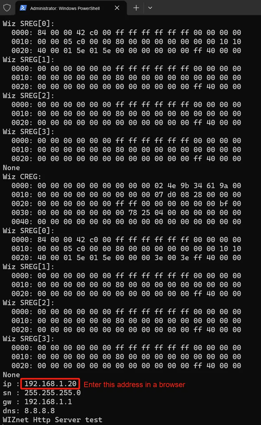
Enter this address in the browser, and the following page will be displayed:
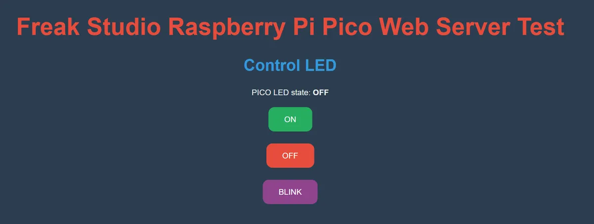
Click the " ON " button, and you will see the LED light up, with the following output in the terminal:

Click other buttons, and you will find that all functions can be executed normally:

3.5.2 HTTP Server Experiment.mp4 19.8 MB
It should be noted that during the LED blinking process, we adopt blocking execution; before the LED blinking is completed, clicking any of the buttons will not trigger any operation.
3.6 MQTT Protocol Experiment
3.6.1 Implementation of MQTT Client Function
Here, we use PyPI (Python Package Index), a Python package sharing platform, to obtain two libraries for implementing the MQTT protocol in the MicroPython environment: micropython-umqtt.simple and micropython-umqtt.robust. These libraries provide MicroPython with the MQTT protocol Client functionality, but they differ in design objectives and features:
micropython-umqtt.simple: is a simpleMQTTClient library, designed for theMicroPythonEnvironmental Design, implemented based on the originalMQTTprotocol. It implements the basic functions of theMQTTprotocol and is suitable for devices with limited resources.- Provides basic
MQTTClient functions, including connecting toMQTTbrokers, publishing messages and subscribing to topics - Suitable for embedded devices with limited resources, free of additional complex functions or redundant code
- Supports
MQTT 3.1.1protocol version core functions, such as connection, publishing, subscription and message receiving
Its address is: https://pypi.org/project/micropython-umqtt.simple/#description .
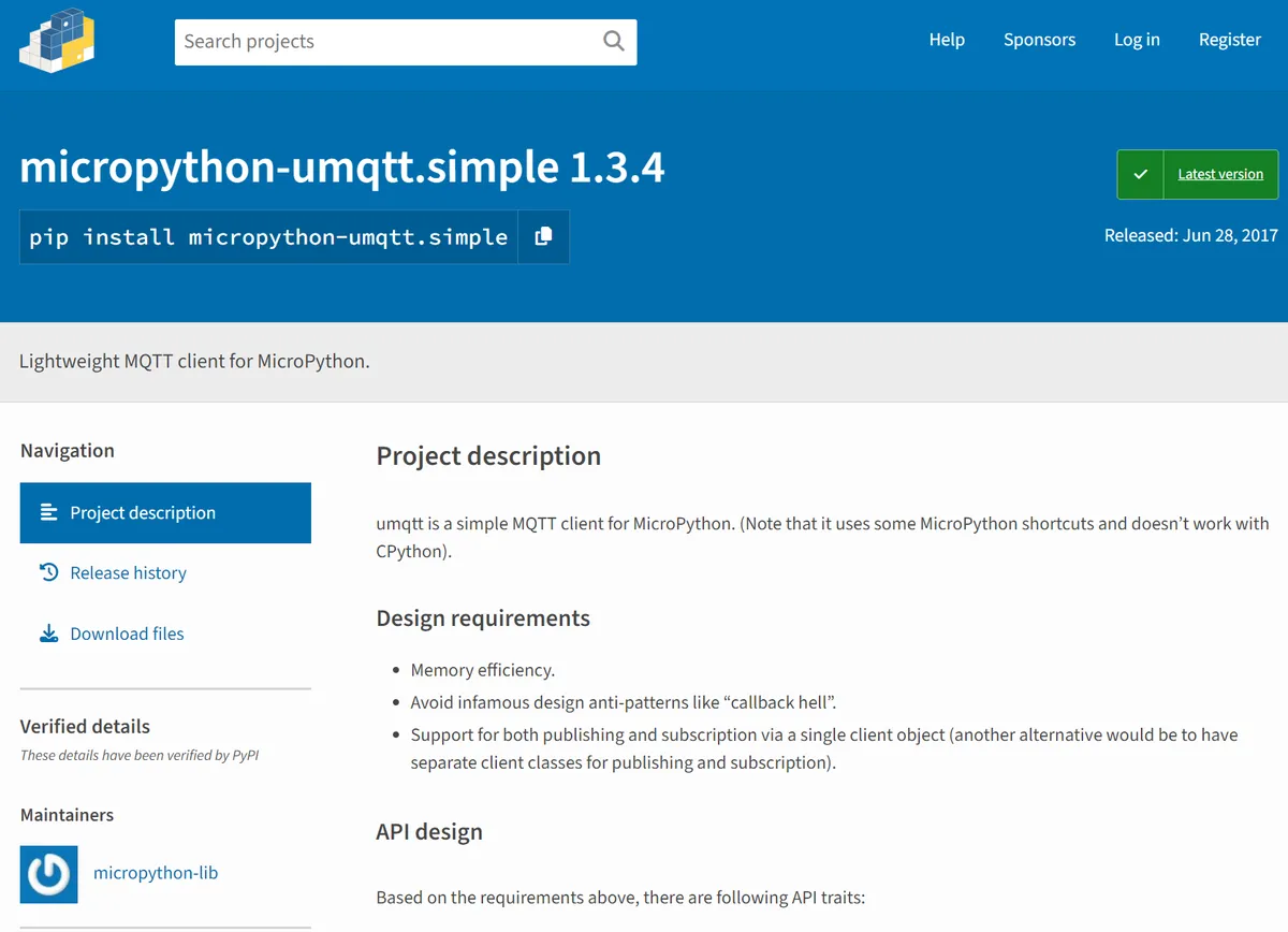
- Provides basic
micropython-umqtt.robust: is an extended version based onmicropython-umqtt.simple, which aims to enhance the robustness of the MQTT Client under unstable network conditions. It addresses some issues that may be encountered inumqtt.simple, such as the handling of network interruptions and reconnections.- Enhanced support for unstable networks, with more robust error handling and reconnection mechanisms provided.
- It features detailed logging capabilities to help debug and monitor the status of the MQTT Client
- It has a built-in automatic reconnection function to cope with network interruptions or connection loss.
The address is: https://pypi.org/project/micropython-umqtt.robust/ .
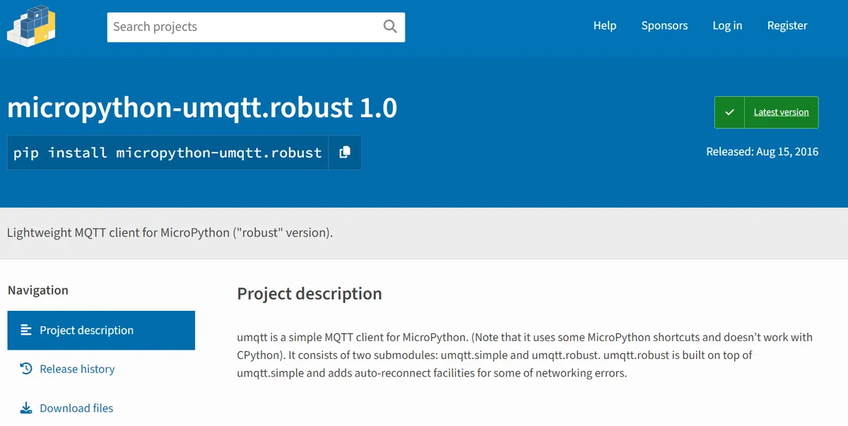
micropython-umqtt.simple The code is as follows:
# Python env   : MicroPython v1.23.0 on Wiznet W5500
# -*- coding: utf-8 -*-
# @Time    : 2024/8/9 AM 11:01
# @Author  : Li Qingshui
# @File    : umqttsimple.py
# @Description : Implement a simple MQTT client class

# ======================================== Import Modules ========================================

# Import the module used for network connections
import usocket as socket
# Import the module used for handling byte streams and binary data
import ustruct as struct
# Import the module used for base conversion
from ubinascii import hexlify
# Import time-related modules
import time

# ======================================== Global Variables ============================================

# ======================================== Functions ============================================

# ======================================== Custom Classes ============================================

# Define an MQTT exception class to handle errors in MQTT operations
class MQTTException(Exception):
    '''
    Custom MQTT exception class, used to handle errors in MQTT protocol operations.

    This class inherits from Python's built-in Exception class and is used to raise specific errors in MQTT client operations.
    '''
    pass

# Define an MQTT client class to implement the basic operations of the MQTT protocol
class MQTTClient:
    """
    MQTTClient class, used to implement the basic operations of the MQTT protocol, including connecting to the server, publishing messages, subscribing to topics, handling messages, etc.

    This class encapsulates the client functions of the MQTT protocol, supports communication with an MQTT server, and provides functions such as message publishing, subscription, and last will message setting.
    Supports SSL/TLS encrypted connections, and allows setting parameters such as keepalive time, username and password.

    Attributes:
        client_id (int): Client ID, used to identify the client.
        server (str): MQTT server address.
        port (int): MQTT server port, default is 0 (automatically select the default port).
        user (str): Username, default is None.
        password (str): Password, default is None.
        keepalive (int): Keepalive time, default is 0.
        ssl (bool): Whether to use an SSL/TLS encrypted connection, default is False.
        ssl_params (dict): SSL/TLS parameters, default is an empty dictionary.
        sock (socket): Socket used for communication between the client and the server.
        pid (int): Packet ID, used to identify MQTT packets.
        cb (callable): Message callback function, used to handle received messages.
        lw_topic (str): Topic of the last will message, default is None.
        lw_msg (str): Content of the last will message, default is None.
        lw_qos (int): QoS level of the last will message, default is 0.
        lw_retain (bool): Whether the last will message is retained, default is False.

    Methods:
        __init__(self, client_id, server, port=0, user=None, password=None, keepalive=0, ssl=False, ssl_params={}):
            Initialize the MQTTClient class instance.

        _send_str(self, s):
            Send string data to the server.

        _recv_len(self):
            Receive a variable-length integer, used to parse the length field of an MQTT packet.

        set_callback(self, f):
            Set the message callback function.

        set_last_will(self, topic, msg, retain=False, qos=0):
            Set the last will message.

        connect(self, clean_session=True):
            Connect to the MQTT server.

        disconnect(self):
            Disconnect from the MQTT server.

        ping(self):
            Send a keepalive request (PINGREQ).

        publish(self, topic, msg, retain=False, qos=0):
            Publish a message to the specified topic.

        subscribe(self, topic, qos=0):
            Subscribe to the specified topic.

        wait_msg(self):
            Wait for and handle a single incoming MQTT message.

        check_msg(self):
            Check whether there is a pending message from the server.
    """
    def __init__(self, client_id: int, server: str, port: int = 0, user: str = None, password: str = None,
                 keepalive: int = 0, ssl: bool = False, ssl_params: dict = {}) -> None:
        '''
        Initialize the MQTT client class

        Args:
            client_id (int): Client ID
            server (str): Server address
            port (int): Server port, default is 0 (automatically select the default port)
            user (str): Username, default is None
            password (str): Password, default is None
            keepalive (int): Keepalive time, default is 0
            ssl (bool): Whether to use SSL, default is False
            ssl_params (dict): SSL parameters, default is an empty dictionary

        Returns:
            None
        '''

        # If no port is specified, use the default port
        if port == 0:
            # If SSL is used, use port 8883, otherwise use 1883
            port = 8883 if ssl else 1883

        self.client_id = client_id
        # Initialize the socket to None
        self.sock = None
        self.server = server
        self.port = port
        self.ssl = ssl
        self.ssl_params = ssl_params
        # Initialize the packet ID to 0
        self.pid = 0
        # Initialize the callback function to None
        self.cb = None
        self.user = user
        self.pswd = password
        self.keepalive = keepalive

        # Initialize the last will topic to None
        self.lw_topic = None
        # Initialize the last will message to None
        self.lw_msg = None
        # Initialize the last will QoS to 0
        self.lw_qos = 0
        # Initialize the last will message as not retained
        self.lw_retain = False

    # Send string data
    def _send_str(self, s: str) -> None:
        '''
        Send string data

        Args:
            s (str): String to send

        Returns:
            None
        '''
        # Send the string length
        self.sock.write(struct.pack("!H", len(s)))
        # Send the string content
        self.sock.write(s)

    # Receive a variable-length integer, used for the length field of an MQTT packet
    def _recv_len(self) -> int:
        '''
        Receive a variable-length integer, used for the length field of an MQTT packet

        Returns:
            int: Received length
        '''
        # Initialize the length to 0
        n = 0
        # Initialize the shift amount to 0
        sh = 0

        # Loop to receive bytes
        while True:
            # Read one byte
            b = self.sock.read(1)[0]
            # Parse the lower 7 bits of the byte
            n |= (b & 0x7F) << sh
            # If the highest bit is 0, it indicates the end
            if not b & 0x80:
                # Return the received length
                return n
                # Otherwise, continue reading the next byte
            sh += 7

    # Set the message callback function
    def set_callback(self, f: callable) -> None:
        '''
        Set the message callback function

        Args:
            f (callable): Callback function

        Returns:
            None
        '''
        # Save the callback function
        self.cb = f

    # Set the last will message
    def set_last_will(self, topic: str, msg: str, retain: bool = False, qos: int = 0) -> None:
        '''
        Set the last will message

        Args:
            topic (str): Topic
            msg (str): Message
            retain (bool): Whether to retain the message. Defaults to False
            qos (int): QoS level. Defaults to 0

        Returns:
            None

        Raises:
            AssertionError: If QoS is not in the valid range or the topic is empty
        '''

        # Verify that QoS is in the valid range
        assert 0 <= qos <= 2
        # Verify that the topic exists
        assert topic

        self.lw_topic = topic
        self.lw_msg = msg
        self.lw_qos = qos
        self.lw_retain = retain

    # Connect to the MQTT server
    def connect(self, clean_session: bool = True) -> int:
        '''
        Connect to the MQTT server

        Args:
            clean_session (bool): Whether to clear the session. Defaults to True

        Returns:
            int: Connection result

        Raises:
            MQTTException: If the connection fails
        '''

        # Create a socket
        self.sock = socket.socket()
        # Get the server address info
        addr = socket.getaddrinfo(self.server, self.port)[0][-1]
        # Connect to the server
        self.sock.connect(addr)

        # If using SSL
        if self.ssl:
            # Import the SSL module
            import ussl
            # Wrap the socket in SSL
            self.sock = ussl.wrap_socket(self.sock, **self.ssl_params)

        # Create the fixed header byte array
        premsg = bytearray(b"\x10\0\0\0\0\0")
        # Create the byte array for the variable header and payload
        msg = bytearray(b"\x04MQTT\x04\x02\0\0")

        # Calculate the total message length
        sz = 10 + 2 + len(self.client_id)
        # Set the clean session flag
        msg[6] = clean_session << 1

        # If using a username and password
        if self.user is not None:
            # Update the message length
            sz += 2 + len(self.user) + 2 + len(self.pswd)
            # Set the username and password flags
            msg[6] |= 0xC0

        # If a keepalive time is set
        if self.keepalive:  # If a keepalive time is set
            # Verify that the keepalive time is in the valid range
            assert self.keepalive < 65536
            # Set the high byte of the keepalive time
            msg[7] |= self.keepalive >> 8
            # Set the low byte of the keepalive time
            msg[8] |= self.keepalive & 0x00FF

        # If a last will message is set
        if self.lw_topic:
            # Update the message length
            sz += 2 + len(self.lw_topic) + 2 + len(self.lw_msg)
            # Set the will QoS
            msg[6] |= 0x4 | (self.lw_qos & 0x1) << 3 | (self.lw_qos & 0x2) << 3
            # Set the will retain flag
            msg[6] |= self.lw_retain << 5

        # Initialize the byte count of the length field
        i = 1

        # If the length exceeds 7 bits
        while sz > 0x7F:
            # Continue processing the length field
            premsg[i] = (sz & 0x7F) | 0x80
            # Shift
            sz >>= 7
            # Increment the byte count
            i += 1
        # Set the length of the last byte
        premsg[i] = sz

        # Send the fixed header
        self.sock.write(premsg, i + 2)
        # Send the variable header and payload
        self.sock.write(msg)

        # Send the client ID
        self._send_str(self.client_id)

        # If a last will message is set
        if self.lw_topic:
            # Send the will topic
            self._send_str(self.lw_topic)
            # Send the will message
            self._send_str(self.lw_msg)

        # If using a username and password
        if self.user is not None:
            # Send the username
            self._send_str(self.user)
            # Send the password
            self._send_str(self.pswd)

        # Read the server response
        resp = self.sock.read(4)

        # Verify the connection acknowledgment packet
        assert resp[0] == 0x20 and resp[1] == 0x02

        # If the connection fails
        if resp[3] != 0:
            # Raise an exception
            raise MQTTException(resp[3])

        # Return the connection result
        return resp[2] & 1

    # Disconnect from the MQTT server
    def disconnect(self) -> None:
        '''
        Disconnect from the MQTT server

        Returns:
            None
        '''
        # Send the disconnect packet
        self.sock.write(b"\xe0\0")
        # Close the socket
        self.sock.close()

    # Send a keepalive request (PINGREQ)
    def ping(self) -> None:
        '''
        Send a keepalive request (PINGREQ)

        Returns:
            None
        '''
        self.sock.write(b"\xc0\0")

    # Publish a message
    def publish(self, topic: str, msg: str, retain: bool = False, qos: int = 0) -> None:
        '''
        Publish a message

        Args:
            topic (str): Topic
            msg (str): Message
            retain (bool): Whether to retain the message. Defaults to False
            qos (int): Quality of service level (0, 1, 2). Defaults to 0

        Returns:
            None

        Raises:
            AssertionError: If the message size exceeds the MQTT protocol limit
        '''

        # Create the basic structure of the MQTT publish packet; QoS defaults to 0 and the retain flag to False
        pkt = bytearray(b"\x30\0\0\0")

        # Set the packet flag bits according to the retain flag and QoS
        pkt[0] |= qos << 1 | retain

        # Calculate the total message size: 2 bytes for the topic length, the rest for the message length
        sz = 2 + len(topic) + len(msg)

        # If QoS is greater than 0, add 2 bytes for the packet identifier (PID)
        if qos > 0:
            sz += 2

        # Assert that the total message size is less than 2097152 bytes (MQTT protocol limit)
        assert sz < 2097152

        # Encode the message size using the variable-length encoding scheme
        i = 1

        while sz > 0x7F:
            pkt[i] = (sz & 0x7F) | 0x80
            sz >>= 7
            i += 1
        pkt[i] = sz

        # Send the constructed publish packet to the server
        self.sock.write(pkt, i + 1)

        # Send the topic string
        self._send_str(topic)

        # If QoS is greater than 0, increment the packet identifier (PID) and send it
        if qos > 0:
            self.pid += 1
            pid = self.pid
            struct.pack_into("!H", pkt, 0, pid)
            self.sock.write(pkt, 2)

        # Send the message content
        self.sock.write(msg)

        # If QoS equals 1, wait for the server's PUBACK response
        if qos == 1:
            while 1:
                op = self.wait_msg()
                if op == 0x40:  # 0x40 indicates a PUBACK packet
                    sz = self.sock.read(1)
                    assert sz == b"\x02"
                    rcv_pid = self.sock.read(2)
                    rcv_pid = rcv_pid[0] << 8 | rcv_pid[1]
                    if pid == rcv_pid:
                        return

        # If QoS equals 2, raise an exception (this code does not implement QoS 2 logic)
        elif qos == 2:
            assert 0

    def subscribe(self, topic: str, qos: int = 0) -> None:
        '''
        Subscribe to a topic

        Args:
            topic (str): Topic
            qos (int): QoS level. Defaults to 0

        Returns:
            None

        Raises:
            AssertionError: If the subscription callback function is not set
            MQTTException: If the server returns an error code
        '''

        # Make sure the subscription callback function is set
        assert self.cb is not None, "Subscribe callback is not set"

        # Create the basic structure of the MQTT subscribe packet
        pkt = bytearray(b"\x82\0\0\0")

        # Increment the packet identifier (PID)
        self.pid += 1
        struct.pack_into("!BH", pkt, 1, 2 + 2 + len(topic) + 1, self.pid)

        # Send the subscribe packet
        self.sock.write(pkt)
        # Send the topic string
        self._send_str(topic)
        # Send the QoS level
        self.sock.write(qos.to_bytes(1, "little"))

        # Wait for the server's SUBACK response
        while 1:
            op = self.wait_msg()
            # 0x90 indicates a SUBACK packet
            if op == 0x90:
                resp = self.sock.read(4)
                assert resp[1] == pkt[2] and resp[2] == pkt[3]
                if resp[3] == 0x80:
                    raise MQTTException(resp[3])
                return

    # Wait for a single incoming MQTT message and process it
    # Subscribed messages are passed to the callback function previously set via the .set_callback() method
    # Other (internal) MQTT messages are handled internally
    def wait_msg(self) -> int:
        '''
        Wait for a single incoming MQTT message and process it

        Returns:
            int: Returns the opcode, or None if no message is received

        Raises:
            OSError: If an empty message is read
            AssertionError: If an invalid PINGRESP packet is received
        '''

        # Read one byte from the server
        res = self.sock.read(1)

        # If no message is received, return None
        if res is None:
            return None

        # If an empty message is received, raise an error
        if res == b"":
            raise OSError(-1)

        # If a PINGRESP packet (0xD0) is received, read its length (should be 0), then return None
        if res == b"\xd0":  # PINGRESP
            sz = self.sock.read(1)[0]
            assert sz == 0
            return None

        # Parse the opcode
        op = res[0]
        # If it is not a publish message (starting with 0x30), return the opcode
        if op & 0xF0 != 0x30:
            return op

        # Read the remaining length of the message
        sz = self._recv_len()

        # Read the topic length
        topic_len = self.sock.read(2)
        topic_len = (topic_len[0] << 8) | topic_len[1]

        # Read the topic content
        topic = self.sock.read(topic_len)

        # Subtract the length already read
        sz -= topic_len + 2

        # If QoS is greater than 0, read the packet identifier (PID)
        if op & 6:
            pid = self.sock.read(2)
            pid = pid[0] << 8 | pid[1]
            sz -= 2

        # Read the message content
        msg = self.sock.read(sz)

        # Call the callback function to process the received message
        self.cb(topic, msg)

        # If QoS is 1, send a PUBACK acknowledgment
        if op & 6 == 2:
            pkt = bytearray(b"\x40\x02\0\0")
            struct.pack_into("!H", pkt, 2, pid)
            self.sock.write(pkt)

        # If QoS is 2, raise an exception (not implemented)
        elif op & 6 == 4:
            assert 0
        return op

    # Check whether there are pending messages from the server.
    def check_msg(self) -> int:
        '''
        Check whether there are pending messages from the server

        Returns:
            int: Returns the opcode, or None if no message is received
        '''
        return self.wait_msg()

# ======================================== Initialization ==========================================

# ========================================  Main Program  ===========================================
micropython-umqtt.simple Two classes are defined in the file:
MQTTExceptionClass: a customMQTTexception class, which is used to handle errors inMQTToperationsMQTTClientclass: implements the basic operations of theMQTTClient, including functions such as connection, disconnection, publishing, and subscription
micropython-umqtt.simple provides the MQTTClient class, which mainly offers the following methods for transmitting data via the MQTT protocol:
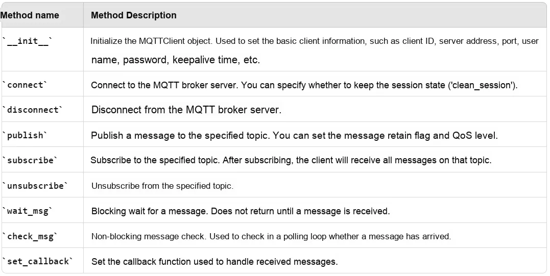
umqtt.robust also defines a MQTTClient class, which inherits all the features of umqttsimple.MQTTClient, and adds a debug parameter and a log method for controlling debug output. This allows users to control whether to output debug information to facilitate troubleshooting.It leverages Python 's exception handling mechanism and infinite loops to override the parent class' s reconnect method, publish method, wait_msg method and check_msg method, so as to address issues such as deadlock or infinite recursion that may occur in the umqttsimple module after encountering a weak network or network disconnection, enabling it to transmit data normally under unstable network conditions.
Here, we make minor modifications to the original umqtt.robust file to make it more concise and better aligned with the principles of Python Object Oriented programming. The code is as follows:
# Python env   : MicroPython v1.23.0 on Wiznet W5500
# -*- coding: utf-8 -*-
# @Time    : 2024/8/9 PM 11:38
# @Author  : Li Qingshui
# @File    : umqttrobust.py
# @Description : This module is used to solve problems such as deadlock or infinite recursion that the umqttsimple module may encounter on a weak or lost network connection

# ======================================== Import Modules ========================================

# Import time-related modules
import time
# Import the umqttsimple module
import umqttsimple

# ======================================== Global Variables ============================================

# ======================================== Functions ============================================

# ======================================== Custom Classes ============================================

# Inherits from the umqttsimple.MQTTClient class, to solve problems such as deadlock or infinite recursion that the umqttsimple module may encounter on a weak or lost network connection
class MQTTClient(umqttsimple.MQTTClient):
    """
    MQTTClient class, inherits from umqttsimple.MQTTClient, used to enhance MQTT client functionality.

    This class adds the following features on top of umqttsimple.MQTTClient:
    - Supports debug mode, which outputs detailed error logs.
    - Automatically reconnects to the MQTT server when the network is unstable or disconnected.
    - Provides a limited number of message checks and retries to avoid infinite blocking.

    Attributes:
        client_id (int): Client ID, used to identify the client.
        server (str): MQTT server address.
        port (int): MQTT server port, default is 0 (automatically select the default port).
        user (str): Username, default is None.
        password (str): Password, default is None.
        keepalive (int): Keepalive time, default is 0.
        ssl (bool): Whether to use an SSL/TLS encrypted connection, default is False.
        debug (bool): Whether to output debug information. Defaults to False.
        ssl_params (dict): SSL/TLS parameters, default is an empty dictionary.
        sock (socket): Socket used for communication between the client and the server.
        pid (int): Packet ID, used to identify MQTT packets.
        cb (callable): Message callback function, used to handle received messages.
        lw_topic (str): Topic of the last will message, default is None.
        lw_msg (str): Content of the last will message, default is None.
        lw_qos (int): QoS level of the last will message, default is 0.
        lw_retain (bool): Whether the last will message is retained, default is False.

    Methods:
        __init__(self, client_id, server, port=0, user=None, password=None, keepalive=0, ssl=False, debug=False, ssl_params={}):
            Initialize the MQTTClient class instance.

        log(self, in_reconnect, e):
            Used to output error information during debugging.

        reconnect(self):
            Reconnect to the MQTT server when the network is unstable.

        publish(self, topic, msg, retain=False, qos=0):
            Publish a message to the specified topic, with support for automatic reconnection.

        wait_msg(self):
            Wait for and process a single incoming MQTT message, with support for automatic reconnection.

        check_msg(self, attempts=2):
            Checks for pending messages from the server, with a limited number of retries.
    """

    def __init__(self, client_id: int, server: str, port: int = 0, user: str = None, password: str = None, keepalive: int = 0, ssl: bool = False, debug: bool = False, ssl_params: dict = {}) -> None:
        '''
        Initialize the MQTT client class

        Args:
            client_id (int): Client ID
            server (str): Server address
            port (int): Server port, default is 0 (automatically select the default port)
            user (str): Username, default is None
            password (str): Password, default is None
            keepalive (int): Keepalive time, default is 0
            ssl (bool): Whether to use SSL, default is False
            debug (bool): Whether to output debug information, default is False
            ssl_params (dict): SSL parameters, default is an empty dictionary

        Returns:
            None
        '''

        # Call the parent class initialization method
        super().__init__(client_id, server, port, user, password, keepalive, ssl, ssl_params, )
        # Initialize the debug attribute, which controls whether debug information is output
        self.debug = debug

    def log(self, in_reconnect: bool, e: Exception) -> None:
        '''
        Used to output error information during debugging

        Args:
            in_reconnect (bool): Whether the error occurred during reconnection
            e (Exception): Error information

        Returns:
            None
        '''

        # Logs are printed only in debug mode (debug=True)
        if self.debug:
            # Determine whether the error occurred during reconnection, and decide the log content accordingly
            if in_reconnect:
                print("mqtt reconnect: %r" % e)
            else:
                print("mqtt: %r" % e)

    def reconnect(self) -> None:
        '''
        Used to reconnect to the MQTT server when the network is unstable

        Returns:
            None
        '''

        # Initialize the retry counter i
        i = 0

        # Loop forever until the connection succeeds
        while True:
            # Try to connect to the MQTT server
            try:
                # Call the parent class connect method to connect. The parameter False means the previous session is not kept
                return super().connect(False)
            # If an OSError exception is caught, the connection failed
            except OSError as e:
                # Call the log method to record the reconnection error information
                self.log(True, e)
                # Increment the retry counter i, which controls the wait time before the next reconnection
                i += 1
                # Wait according to the retry count i to prevent frequent retries
                time.sleep(i)

    def publish(self, topic: str, msg: str, retain: bool = False, qos: int = 0) -> None:
        '''
        Define a function that publishes messages and handles possible publish failures when the network is unstable

        Args:
            topic (str): Topic
            msg (str): Message
            retain (bool): Whether to retain the message. Defaults to False
            qos (int): QoS level. Defaults to 0

        Returns:
            None
        '''

        # Loop forever until the message is published successfully
        while True:
            # Try to publish the message
            try:
                # Call the parent class publish method to publish the message to the specified topic
                return super().publish(topic, msg, retain, qos)
            # Catch the OSError exception raised when publishing a message
            except OSError as e:
                # Call the log method to record the error information of the publish failure
                self.log(False, e)
            # If publishing fails, try to reconnect to the MQTT server and try publishing again in the next loop iteration
            self.reconnect()

    def wait_msg(self) -> int:
        '''
        Define a function that waits for messages and handles possible wait failures when the network is unstable
        Runs in blocking mode and returns only when a message is received

        Returns:
            int: Returns the opcode
        '''

        # Loop forever until a message is received successfully
        while True:
            # Try to receive the message
            try:
                # Call the parent class wait_msg method to wait for and receive the message
                return super().wait_msg()
            # Catch the OSError exception raised when receiving a message
            except OSError as e:
                # Call the log method to record the error information of the receive failure
                self.log(False, e)
            # If receiving the message fails, try to reconnect to the MQTT server and try receiving the message again in the next loop iteration
            self.reconnect()

    def check_msg(self, attempts: int = 2) -> int:
        '''
        Define a function that checks for messages and handles possible check failures when the network is unstable
        Provides a limited number of message checks and retries

        Args:
            attempts (int): Number of retries, default is 2

        Returns:
            int or None: Returns the opcode, or None if no message is received
        '''
        # Loop to check for messages, with at most attempts tries
        while attempts:
            # Set the socket to non-blocking mode to ensure the wait_msg method does not block waiting for messages
            self.sock.setblocking(False)

            # Try to receive the message
            try:
                # Call the parent class wait_msg method to receive the message
                return super().wait_msg()
            #  Catch the OSError exception raised when receiving a message
            except OSError as e:
                # Call the log method to record the error information of the message receive failure
                self.log(False, e)
            # If receiving the message fails, try to reconnect to the MQTT server
            self.reconnect()
            # Decrease the remaining attempts; if the attempts are used up, exit the loop
            attempts -= 1

# ======================================== Initialization ==========================================

# ========================================  Main Program  ===========================================
Compared with the original umqtt.robust file, the changes are as follows:
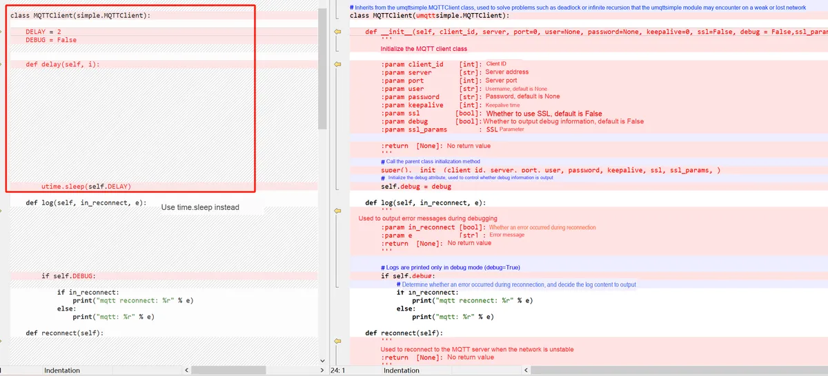
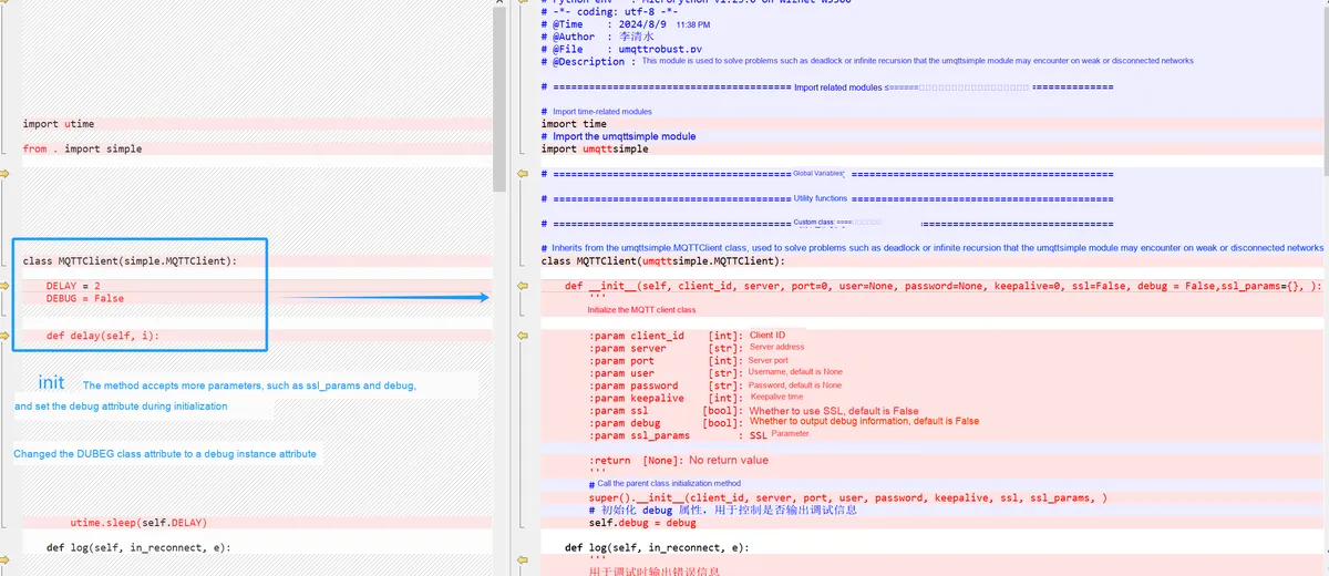
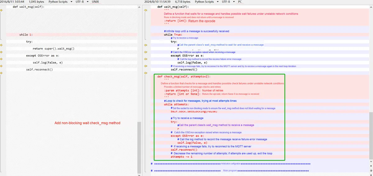
We will micropython-umqtt.simple and micropython-umqtt.robust libraries are named umqttsimple.py file and umqttrobust.py file respectively, saved in the same folder, and this folder is defined as the source file root directory to facilitate the burning of multiple Python files:
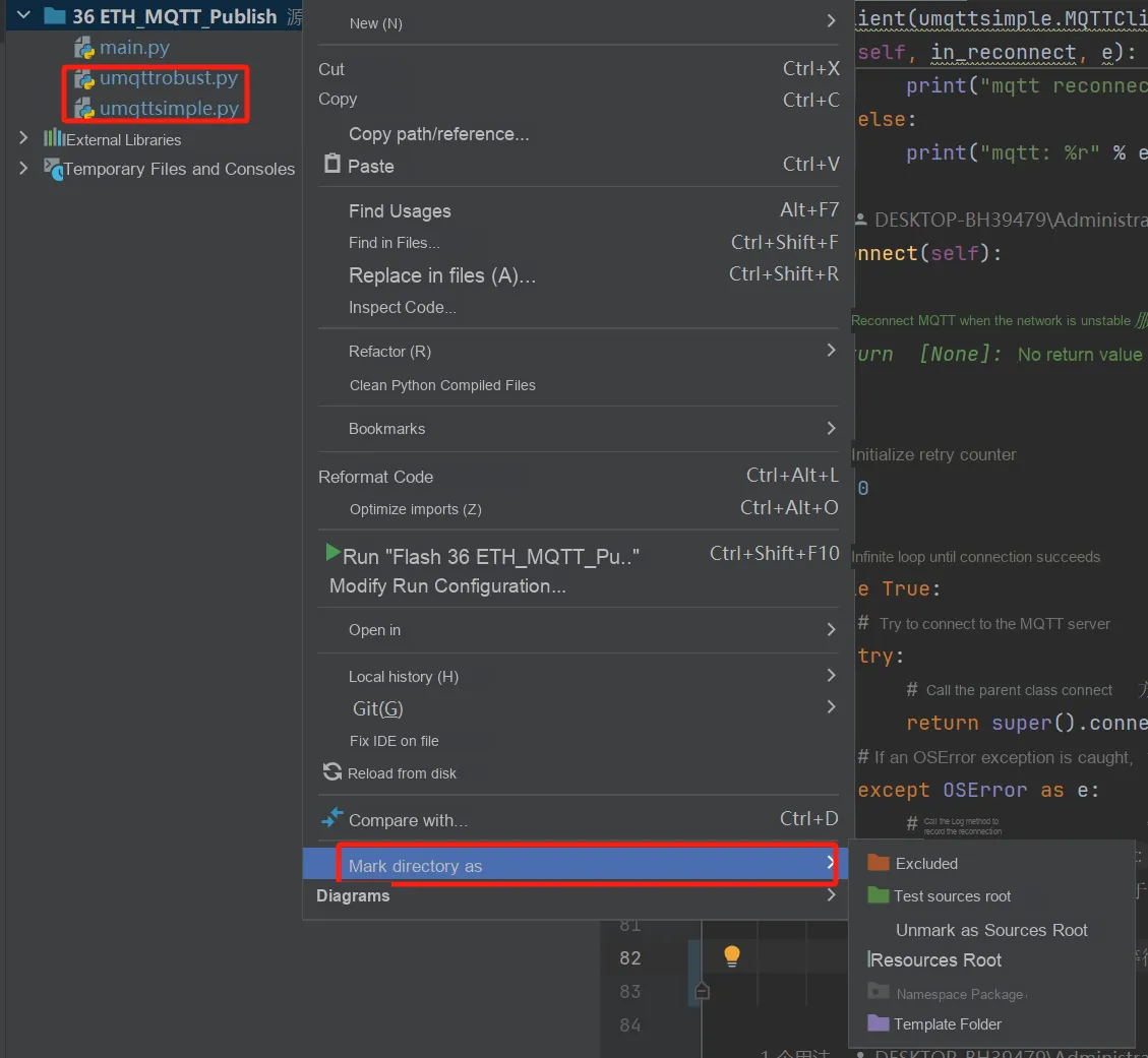
The relationship between the two files and the MQTTClient class in their respective files is as follows:
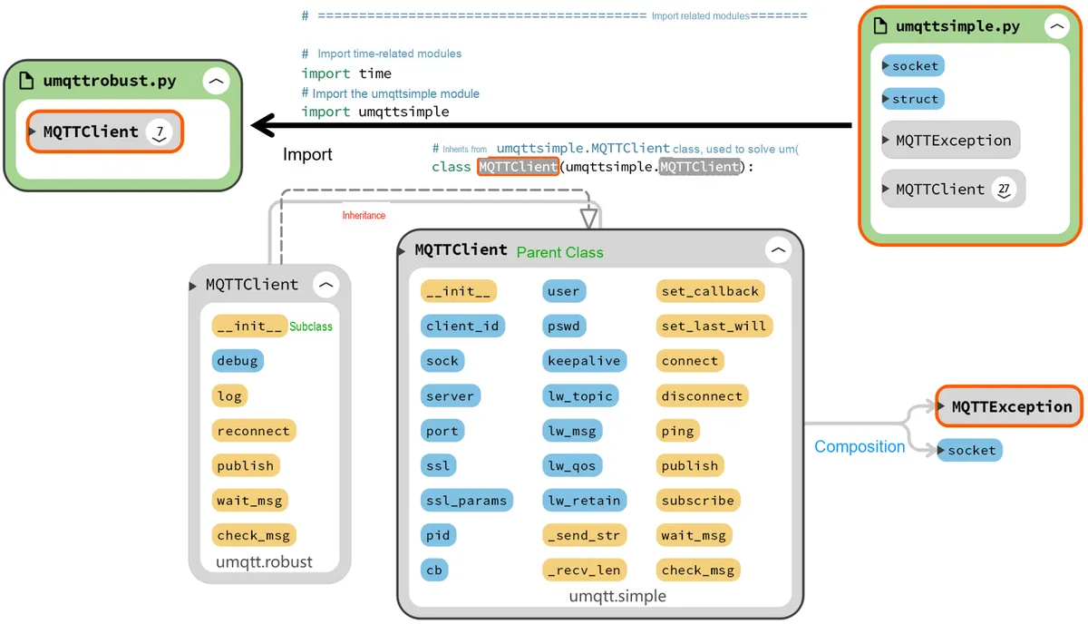
3.6.2 Configuration of MQTT Broker Message Broker Server
Based on the deployment method, MQTT Broker message brokers can be divided into the following types:
- On-premises
MQTT Broker: deployed on local servers or in a private Data center, giving users full control; suitable for scenarios with high requirements for data privacy or low reliance on external networks; users need to manage and maintain the hardware and software environment on their own. Common on-premisesMQTT Brokers includeEclipse Mosquitto,EMQX,VerneMQ, etc. - Cloud-hosted
MQTT Broker: deployed on the platform of a cloud service provider, eliminating the need for users to manage the underlying hardware and infrastructure; it operates on a pay-as-you-go model, making it suitable for scenarios requiring elastic scaling and rapid deployment, and is typically integrated with other services of the Cloud Computing Platform, such as data storage, analytics, and security. Common cloud-hostedMQTT Brokers includeAWS IoT Core,Microsoft Azure IoT Hub,Google Cloud IoT Core,IBM Watson IoT Platform, etc. - Hybrid-deployed
MQTT Broker: It combines the advantages of local deployment and cloud services, with part of data processing completed locally and part of data synchronizable via the cloud; it is suitable for scenarios requiring edge computing functions or high fault tolerance for network connections. Commonly used hybrid-deployedMQTT BrokerincludeAWS Greengrass,Azure IoT Edge,EMQX Edgeand so on. - Embedded Deployment Type
MQTT Broker: Lightweight, designed specifically for resource-constrained embedded systems, deployed on IoT devices, gateways or edge devices, usually used for device communication within local area networks, and suitable for IoT scenarios requiring low latency, local processing and fast response. Commonly used embedded deployment typeMQTT BrokerincludeNanoMQ,Moquette,Eclipse Paho.
Here, we will use the free public EMQ provided by MQTT Broker. This Broker is created based on EMQX Cloud, which is a fully managed EMQX Cloud that delivers highly reliable and scalable MQTT cloud service with MQTT communication capabilities. We use the MQTTX Client software to connect to EMQ. After opening MQTTX, first click the plus sign on the left side of the software to create a Client connection, following the steps shown in the figure below:
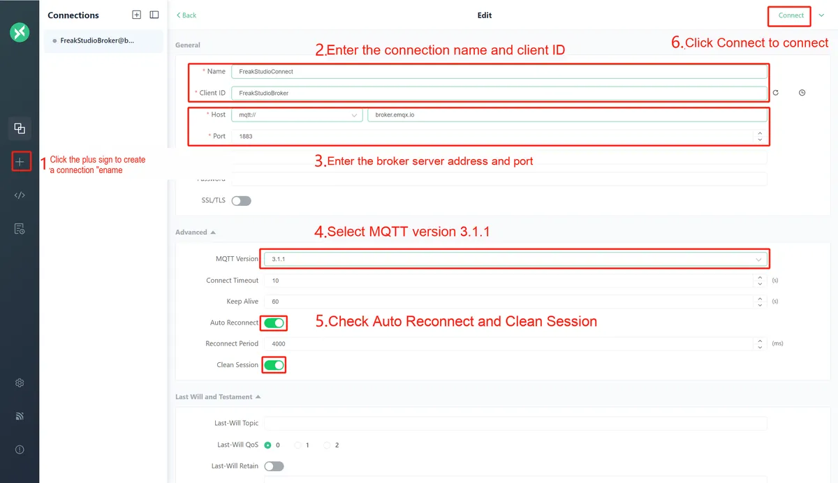
Set the parameters as follows:
连接名称 Name:FreakStudioConnect
客户端ID Client ID:FreakStudioMQTTX
服务器地址 Host:mqtt://broker.emqx.io
端口 Port:1883
MQTT版本 MQTT Version:3.1.1
Setting Clean Session to True means that after the Client goes offline and comes back online, it will not be able to receive messages sent during its offline period.
If the following interface appears, it indicates that the connection has been created successfully:
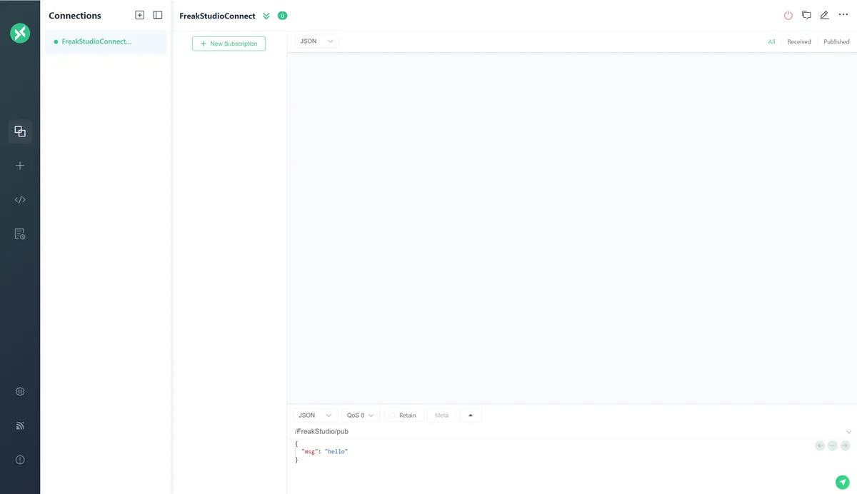
Once the connection is successfully created, you will be directed to the main interface of the connection. Click the collapse button next to the connection name at the top to expand and display several basic pieces of information of this configuration, so that you can quickly modify the common configurations of this connection. Note that you need to disconnect the connection before making modifications, and the changes will take effect after you click to reconnect. When the connection is disconnected, you can also click the configuration button on the right to modify more connection configurations.
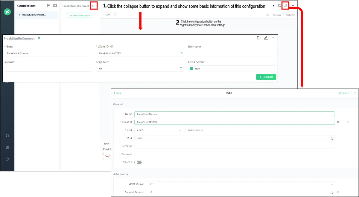
3.6.1 MQTTX Configuration.mp4 4.8 MB
Next, we will conduct two experiments to create a MQTT Client on the Raspberry Pi Pico, and select topics for publishing and subscribing.
Note that when conducting MQTT Client experiments, you need to connect the Ethernet port of the W5500 module to a router for normal operation.
3.6.3 MQTT Client Publishing Experiment
In the following code, we implement a Wiznet W5500 module via MicroPython MQTT Client that can communicate with the EMQX Cloud -provided MQTT Broker. After connecting to the network and initializing the W5500 module, the program connects to the MQTT server, and uses a timer to send heartbeat packets to maintain the connection. Subsequently, the Client cyclically publishes predefined JSON messages to the specified topic, and finally disconnects the MQTT connection and releases resources after all publishing operations are completed.
The following code can be found in the material package we provide, at the elegance-devkit v1\Demo\48 ETH_MQTT_Publish folder.
The sample code is as follows:
# Python env   : MicroPython v1.23.0 on Wiznet W5500
# -*- coding: utf-8 -*-
# @Time    : 2024/8/9 AM 11:15
# @Author  : Li Qingshui
# @File    : main.py
# @Description : Implements the Pub (publish) function of the MQTT client

# ======================================== Import Modules ========================================

# Import hardware-related modules
from machine import Pin,SPI,reset,Timer
# Import time-related modules
import time
# Import network-related modules
import network
# Import the socket module used to create and manage network connections
from usocket import socket
# Import the MQTT client
from umqttrobust import MQTTClient
# Import the json encoding library
import json

# ======================================== Global Variables ============================================

# Device IP address
ip = '192.168.1.20'
sn = '255.255.255.0'
gw = '192.168.1.1'
dns= '8.8.8.8'
# Tuple object used for the network connection
netinfo=(ip, sn, gw, dns)

# MQTT configuration
mqtt_params = {
    'url': 'broker.emqx.io',           # MQTT server address
    'port': 1883,                      # MQTT server port
    'clientid': 'FreakStudioDevice',   # MQTT client ID of this device
    'pubtopic': '/FreakStudio/pub',    # Topic to publish to
    'pubqos': 0,                       # QoS level for publishing
    }

# Message content to publish
msg = { 'clientid' : 'FreakStudioDevice',
        'MQTT_Version' : 'v3.1.1',
        'Device' : 'raspberry pi pico',
        'Name' : 'FreakStudio MQTT Sub Test',
    }
# Encode the message content as json
topic_msg = json.dumps(msg)

# Record the number of times the timer has run
timer_count = 0

# MQTT client instance
client = None

# ======================================== Functions ============================================

def w5x00_init() -> network.WIZNET5K:
    '''
    Initialize a network.WIZNET5K instance, set a static IP address, and connect.

    Returns:
        network.WIZNET5K: The network interface instance that was initialized and connected successfully.
    '''

    # Declare global variables
    global netinfo

    # Initialize the SPI object
    spi = SPI(0, 2_000_000, mosi=Pin(19), miso=Pin(16), sck=Pin(18))
    # Instantiate the network.WIZNET5K class, passing in the chip select pin CS and reset pin RST
    nic = network.WIZNET5K(spi, Pin(17), Pin(20))
    # Activate the network interface
    nic.active(True)

    try:
        print("\r\nConfiguring DHCP")
        # Try to use DHCP to dynamically obtain network configuration such as IP address, subnet mask, gateway and DNS server
        nic.ifconfig('dhcp')
    except:
        print("\r\nDHCP fails, use static configuration")
        # If DHCP fails, use the static IP address configuration
        nic.ifconfig(netinfo)

    # Loop while the network is not connected
    while not nic.isconnected():
        time.sleep(1)
        # Output register information
        print(nic.regs())

    # Print the configured IP address
    print('ip :', nic.ifconfig()[0])
    print('sn :', nic.ifconfig()[1])
    print('gw :', nic.ifconfig()[2])
    print('dns:', nic.ifconfig()[3])

    # Return the network.WIZNET5K instance
    return nic

def mqtt_connect() -> MQTTClient:
    '''
    Connect to the MQTT server.

    Returns:
        MQTTClient: The MQTT client instance that connected successfully.
    '''
    global client_id, mqtt_server

    # Create an MQTT client instance, with the keep-alive time of the connection set to 60 seconds
    client = MQTTClient(mqtt_params['clientid'], mqtt_params['url'], mqtt_params['port'],keepalive=60)
    # Connect to the MQTT server
    client.connect()
    # Print the message indicating a successful connection
    print('Connected to %s MQTT Broker'%(mqtt_params['url']))
    # Return the MQTT client instance
    return client

def timer_callback(t: Timer) -> None:
    '''
    Timer callback function, used to send heartbeat packets.

    Args:
        t (Timer): Timer instance.

    Returns:
        None
    '''

    # Declare global variables
    global timer_count, client

    # Increment the timer count by one
    timer_count = timer_count + 1

    # If the timer count is greater than or equal to 30
    if timer_count >= 30:
        # Reset the timer count
        timer_count = 0
        # Send a heartbeat packet
        client.ping()

# ======================================== Custom Classes ============================================

# ======================================== Initialization ==========================================

# Delay 3s, wait for the device to power up
time.sleep(3)
# Print debug information
print("FreakStudio : Using WIZNET5K Ethernet Device to connect to MQTT Broker as a Publisher")

# Initialize the w5500 module
nic = w5x00_init()

try:
    # Try to connect to the MQTT server
    client = mqtt_connect()
except OSError as e:
    # Print exception-related information and get the detailed traceback of the exception
    print('raise exception : {}'.format(e))
    # Reconnect and reset when the connection fails
    client.reconnect()

# Initialize the timer instance to send MQTT heartbeat packets periodically
timer = Timer(-1)
# The timer calls the timer_callback function once every 1 s
timer.init(freq=1, mode=Timer.PERIODIC, callback=timer_callback)

# ========================================  Main Program  ===========================================

# Publish 10 times in a loop
for i in range(10):
    try:
        # Publish the message to the specified topic
        client.publish(mqtt_params['pubtopic'],topic_msg,qos = mqtt_params['pubqos'])
        # Print debug information
        print('Message Published: %s' % topic_msg)
        # Wait 3 seconds
        time.sleep(3)
    except Exception as e:
        # Print exception-related information and get the detailed traceback of the exception
        print("Failed to publish message")
        print('raise exception : {}'.format(e))

# Disconnect from the MQTT server
client.disconnect()
# Stop the timer
timer.deinit()
Here, we set up a timer that invokes a callback function every 1 second, and when the timer count reaches 30 (i. e., 30 seconds), it sends MQTT Broker a MQTT heartbeat packet to maintain the connection. In the main program, we loop 10 times, and in each iteration, we publish a MQTT - JSON -encoded message to the specified topic '/FreakStudio/pub' and print debug information.
The overall flow chart is shown as follows:
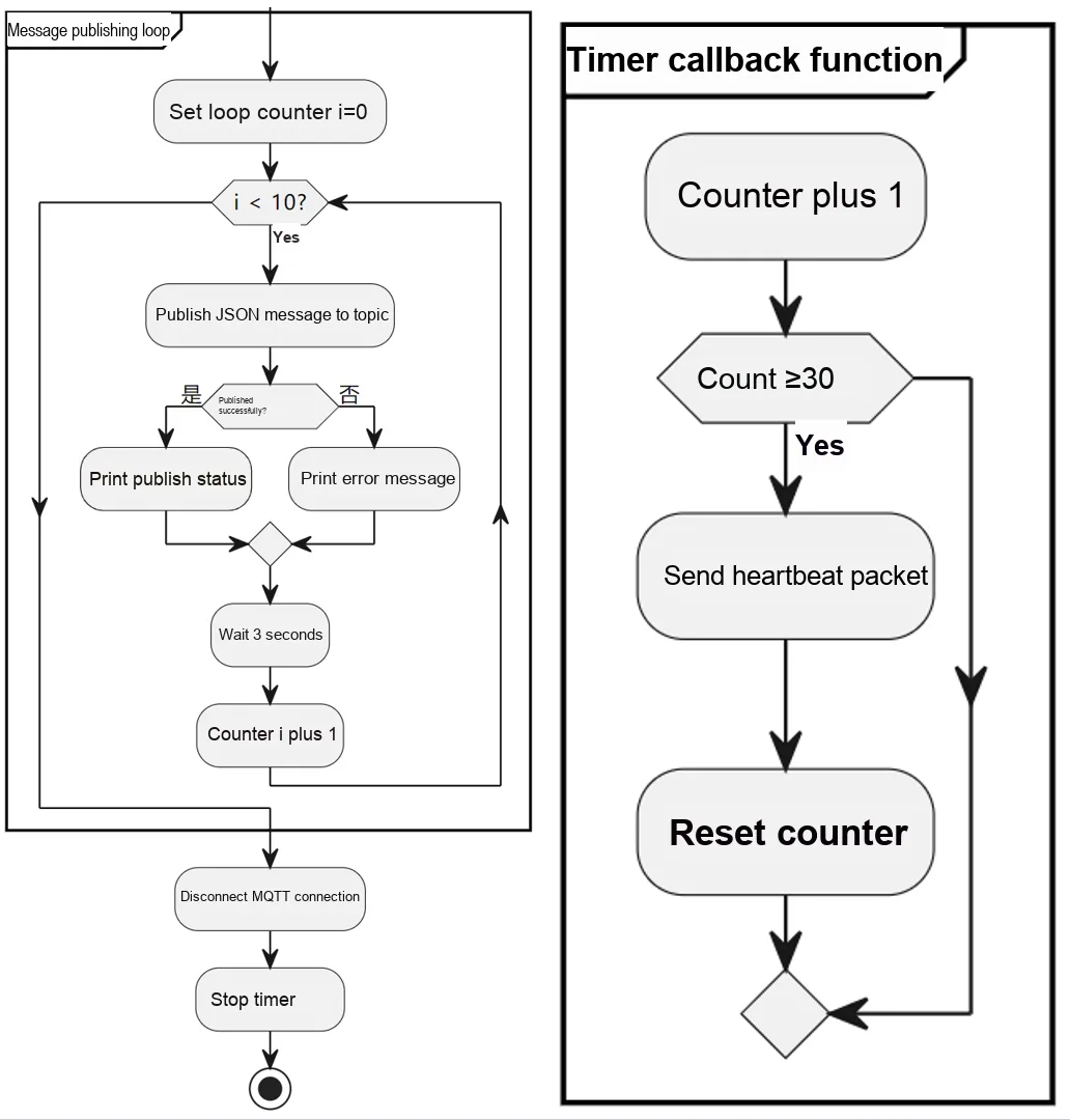
Meanwhile, we need to configure the MQTTX software to subscribe to the '/FreakStudio/pub' topic. First, establish a connection between the Client and the server. Click the button in the lower left corner to quickly subscribe to a Topic, and Topic will immediately start receiving messages after successful subscription:
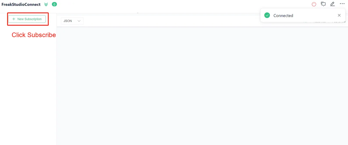
The theme parameters are set as follows:
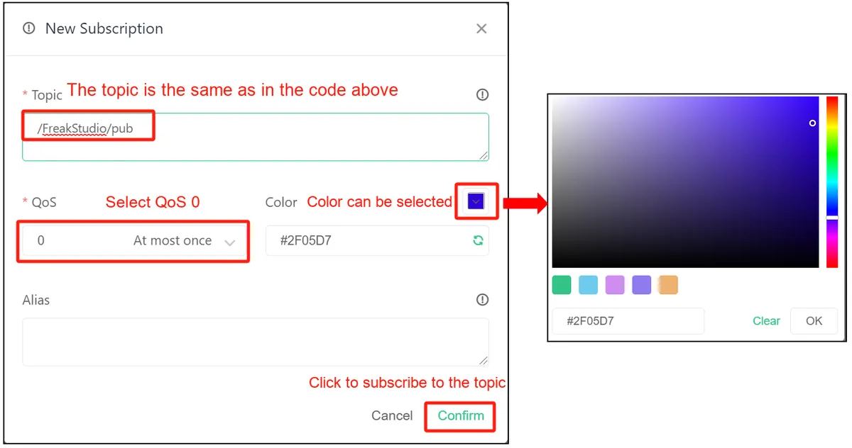
Each Topic will be randomly assigned a color marker, and you can also open the color picker to customize the color of the marker. Click the rightmost button at the top of the subscription list on the page to hide the subscription list for more display space.
Since the Raspberry Pi Pico sends data in JSON format, we need to set the data display format to JSON:
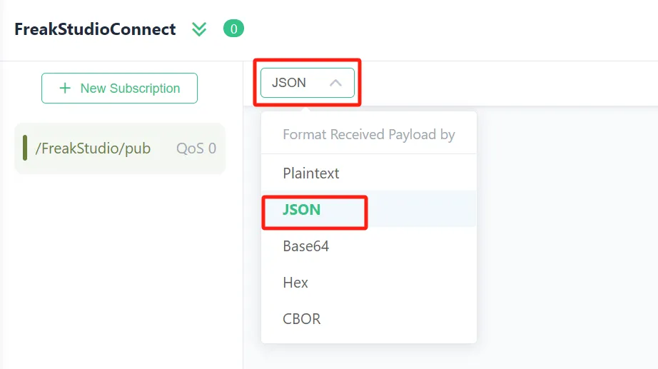
Burn the code, open the terminal, and you will see the following display:
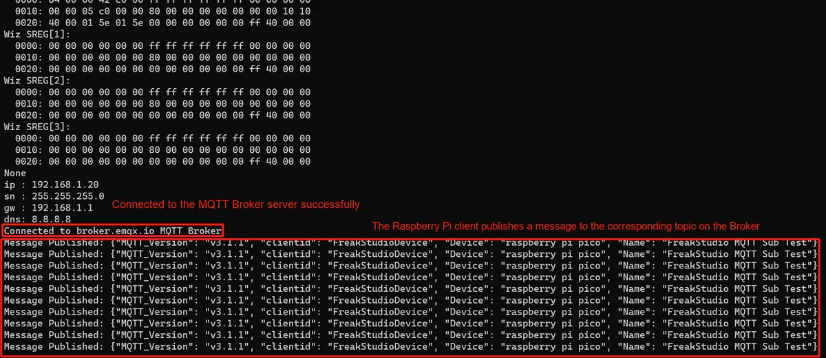
In MQTTX, we can see that the PC Client displays the received messages related to the corresponding topic:
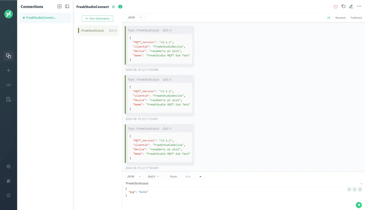
We can also click the button on the left to view MQTTX software connection records:
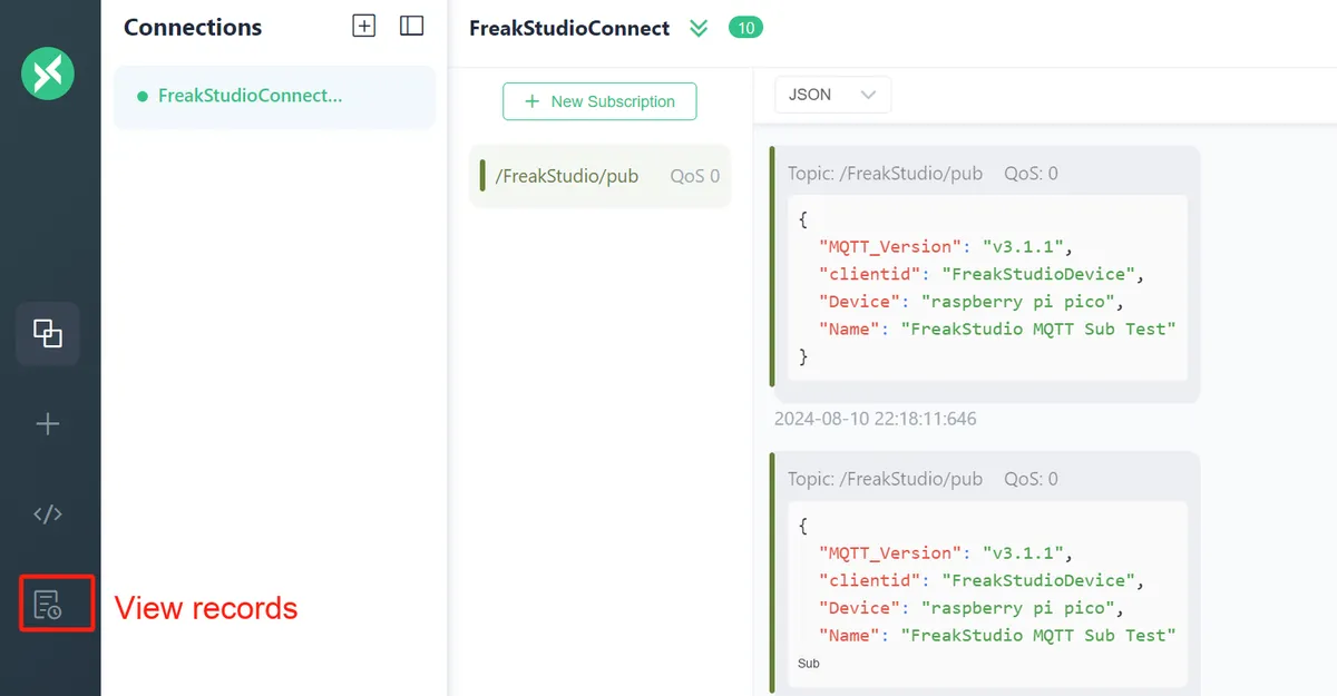
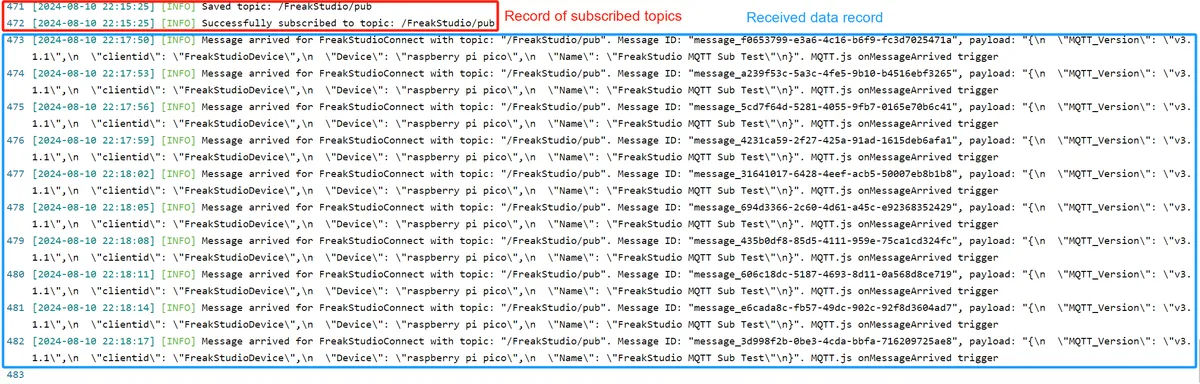
3.6.2 MQTT Client.mp4 22.8 MB
3.6.4 MQTT Client Subscription Experiment
In the following code, we connect to the network via the W5500 module, and implement an MQTT Client function using MicroPython. The program initializes the network, connects to the MQTT server, sets a timer to maintain the connection, subscribes to topics and receives messages. When a message sent by the PC Client to the topic is received (in fact, the message sent by the PC Client to the topic is distributed by the MQTT broker to the Raspberry Pi Client), a callback function is triggered to process the message and republish the message to another topic.The entire process continues until 10 messages are received, after which the Client disconnects and stops the timer.
The following code can be found in the elegance-devkit v1\Demo\49 ETH_MQTT_Subscribe folder within the resource package we provided.
The sample code is as follows:
# Python env   : MicroPython v1.23.0 on Wiznet W5500
# -*- coding: utf-8 -*-
# @Time    : 2024/8/10 PM 10:22
# @Author  : Li Qingshui
# @File    : main.py
# @Description : Implements the Sub (subscribe) function of the MQTT client

# ======================================== Import Modules ========================================

# Import hardware-related modules
from machine import Pin,SPI,reset,Timer
# Import time-related modules
import time
# Import network-related modules
import network
# Import the socket module used to create and manage network connections
from usocket import socket
# Import the MQTT client
from umqttrobust import MQTTClient
# Import the json encoding library
import json

# ======================================== Global Variables ============================================

# Device IP address
ip = '192.168.1.20'
sn = '255.255.255.0'
gw = '192.168.1.1'
dns= '8.8.8.8'
# Tuple object used for the network connection
netinfo=(ip, sn, gw, dns)

# MQTT configuration
mqtt_params = {
    'url': 'broker.emqx.io',           # MQTT server address
    'port': 1883,                      # MQTT server port
    'clientid': 'FreakStudioDevice',   # MQTT client ID of this device
    'pubtopic': '/FreakStudio/pub',    # Topic to publish to
    'subtopic': '/FreakStudio/sub',    # Topic to subscribe to
    'pubqos': 0,                       # QoS level for publishing
    'subqos': 0,                       # QoS level for subscribing
    }

# Record the number of times the timer has run
timer_count = 0
# MQTT client instance
client = None
# MQTT receive count
msg_recv_count = 0

# ======================================== Functions ============================================

def w5x00_init() -> network.WIZNET5K:
    '''
    Initialize a network.WIZNET5K instance, set a static IP address, and connect.

    Returns:
        network.WIZNET5K: The network interface instance that was initialized and connected successfully.
    '''

    # Declare global variables
    global netinfo

    # Initialize the SPI object
    spi = SPI(0, 2_000_000, mosi=Pin(19), miso=Pin(16), sck=Pin(18))
    # Instantiate the network.WIZNET5K class, passing in the chip select pin CS and reset pin RST
    nic = network.WIZNET5K(spi, Pin(17), Pin(20))
    # Activate the network interface
    nic.active(True)

    try:
        print("\r\nConfiguring DHCP")
        # Try to use DHCP to dynamically obtain network configuration such as IP address, subnet mask, gateway and DNS server
        nic.ifconfig('dhcp')
    except:
        print("\r\nDHCP fails, use static configuration")
        # If DHCP fails, use the static IP address configuration
        nic.ifconfig(netinfo)

    # Loop while the network is not connected
    while not nic.isconnected():
        time.sleep(1)
        # Output register information
        print(nic.regs())

    # Print the configured IP address
    print('ip :', nic.ifconfig()[0])
    print('sn :', nic.ifconfig()[1])
    print('gw :', nic.ifconfig()[2])
    print('dns:', nic.ifconfig()[3])

    # Return the network.WIZNET5K instance
    return nic

def mqtt_connect() -> MQTTClient:
    '''
    Connect to the MQTT server.

    Returns:
        MQTTClient: The MQTT client instance that connected successfully.
    '''
    global client_id, mqtt_server

    # Create an MQTT client instance, with the keep-alive time of the connection set to 60 seconds
    client = MQTTClient(mqtt_params['clientid'], mqtt_params['url'], mqtt_params['port'],keepalive=60)
    # Connect to the MQTT server
    client.connect()
    # Print the message indicating a successful connection
    print('Connected to %s MQTT Broker'%(mqtt_params['url']))
    # Return the MQTT client instance
    return client

def timer_callback(t: Timer) -> None:
    '''
    Timer callback function, used to send heartbeat packets.

    Args:
        t (Timer): Timer instance.

    Returns:
        None
    '''

    # Declare global variables
    global timer_count, client

    # Increment the timer count by one
    timer_count = timer_count + 1

    # If the timer count is greater than or equal to 30
    if timer_count >= 30:
        # Reset the timer count
        timer_count = 0
        # Send a heartbeat packet
        client.ping()

def sub_callback(topic: bytes, msg: bytes) -> None:
    '''
    Callback function for the subscribed topic, used to process messages of the subscribed topic.

    Args:
        topic (bytes): The subscribed topic.
        msg (bytes): The message received for the corresponding topic.

    Returns:
        None
    '''
    # Declare global variables: MQTT client instance + receive counter
    global client, msg_recv_count

    # Decode the topic and message (transmitted as byte streams in MQTT) and convert them to UTF-8 strings
    topic = topic.decode('utf-8')
    msg = msg.decode('utf-8')

    # Determine whether the received topic is the configured subscribed topic
    if topic == mqtt_params['subtopic']:
        # Increment the receive count (each time a message of the target topic is received, count +1)
        msg_recv_count += 1

        # Print the received topic, message content, and current receive count
        print(f"\r\ntopic: {topic} \r\nrecv: {msg} \r\ncurrent receive count: {msg_recv_count}")

        # Include the receive count when publishing the message (key change: the message format contains count)
        publish_msg = f'recv: {msg} | total receive count: {msg_recv_count}'
        client.publish(mqtt_params['pubtopic'], publish_msg, qos=mqtt_params['pubqos'])

        # Print the sent topic and the message content with the count
        print(f'\r\ntopic: {mqtt_params["pubtopic"]} \r\nsend: {publish_msg}')

# ======================================== Custom Classes ============================================

# ======================================== Initialization ==========================================

# Delay 3s, wait for the device to power up
time.sleep(3)
# Print debug information
print("FreakStudio : Using WIZNET5K Ethernet Device to connect to MQTT Broker as a Subscriber")

# Initialize the w5500 module
nic = w5x00_init()

try:
    # Try to connect to the MQTT server
    client = mqtt_connect()
except OSError as e:
    # Print exception-related information and get the detailed traceback of the exception
    print('raise exception : {}'.format(e))
    # Reconnect and reset when the connection fails
    client.reconnect()

# Initialize the timer instance to send MQTT heartbeat packets periodically
timer = Timer(-1)
# The timer calls the timer_callback function once every 1 s
timer.init(freq=1, mode=Timer.PERIODIC, callback=timer_callback)

# ========================================  Main Program  ===========================================

# Set the callback function; when a message of the subscribed topic is received, call the sub_callback function to process it
client.set_callback(sub_callback)

# Loop forever until the subscription succeeds and the loop is exited
while True:
    try:
        # Subscribe to the specified topic and set the QoS level in order to receive messages of that topic
        client.subscribe(mqtt_params['subtopic'],mqtt_params['subqos'])
        # Print the message indicating a successful subscription, showing the subscribed topic
        print('subscribed to %s'%mqtt_params['subtopic'])
        # Exit the loop after a successful subscription
        break
    except OSError as e:
        # Print exception-related information and get the detailed traceback of the exception
        print('raise exception : {}'.format(e))
        # Resubscribe and reset when the subscription fails
        client.reconnect()

# Receive messages 10 times in a row
while msg_recv_count<10:
    # Wait to receive messages
    msg = client.wait_msg()

# Disconnect from the MQTT server
client.disconnect()
# Stop the timer
timer.deinit()
The core functions of its data processing are as follows: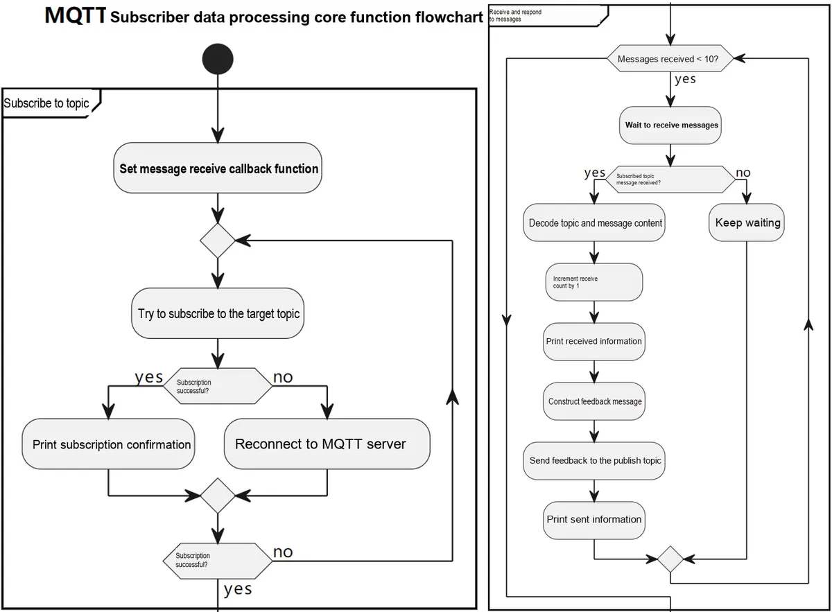
- Subscribe to Topics
- Set the message receiving callback function (
client.set_callback (sub_callback)) to specify the processing logic when a message for the subscribed topic is received. - Enter a loop to attempt subscribing to the target topic (
client.subscribe ()); if the subscription fails, reconnect (client.reconnect ()) until the subscription succeeds and the confirmation message is printed.
- Set the message receiving callback function (
- Receive and respond to messages Enter a loop to wait for incoming messages (
while msg_recv_count < 10) until 10 messages have been received:- When a message for the subscribed topic (
/FreakStudio/sub) is received,sub_callbackwill be triggered:- Decode the topic and message (ByteFlow → UTF-8 string).
- Increment the receive count (
msg_recv_count) by 1, and print the currently received topic, message content and the count. - Send a feedback message containing the reception count to the publishing topic (
/FreakStudio/pub), for example"recv: xxx | total receive count: 1", and print the sending information.
- When a message for the subscribed topic (
After receiving a total of 10 messages:
- Disconnect from the MQTT server (
client.disconnect ()). - Stop the timer (
timer.deinit ()) to terminate heartbeat maintenance.
Meanwhile, we need to configure the MQTTX software to subscribe to the '/FreakStudio/sub' topic:
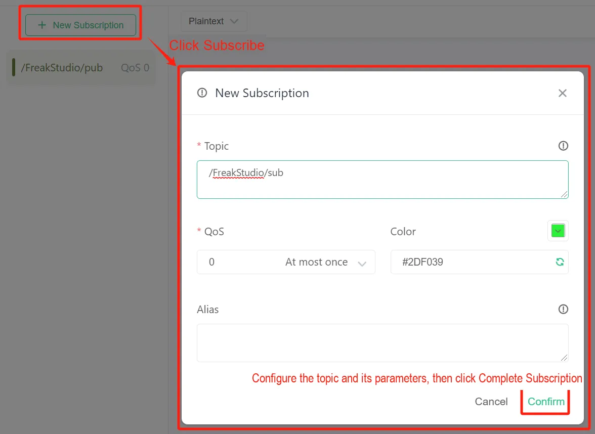
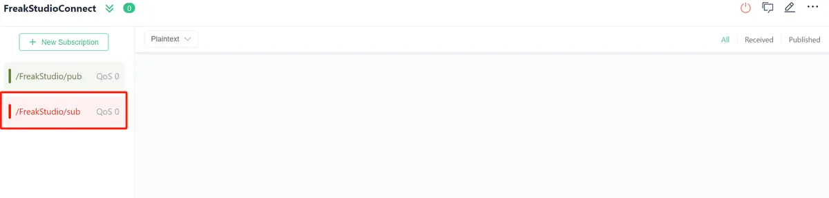
Here, since the data sent and received by both of our topics are in string format, we need to set the display format for published and subscribed data to Plaintext:
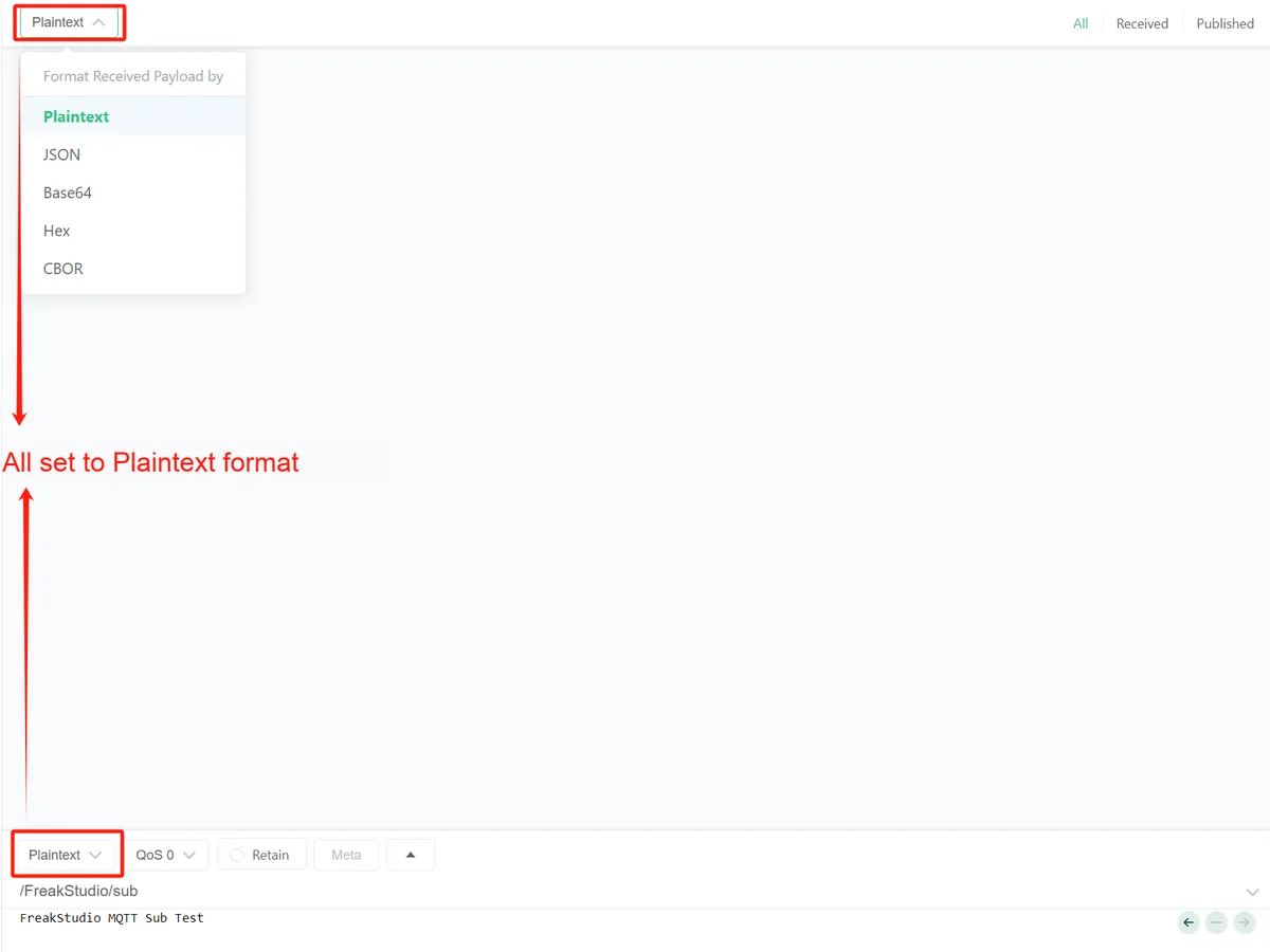
Next, in the input field below the main connection page, enter the topic we want to publish on the PC Client '/FreakStudio/sub':

Enter the content to be sent, then press the arrow button at the bottom right to complete the sending. Here, the content we publish is: a string FreakStudio MQTT Sub Test.
Burn the code, open the terminal, and the output is as follows:
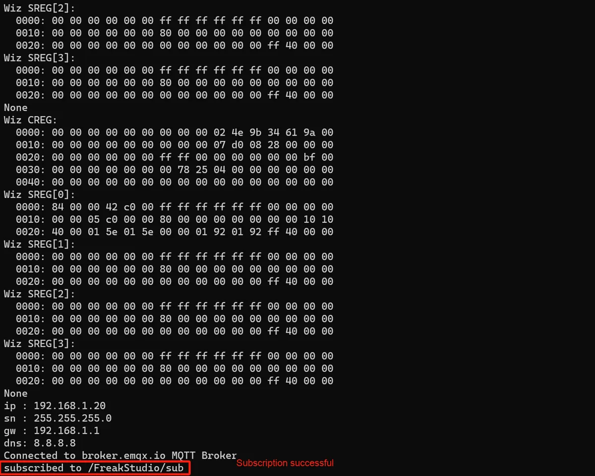
At this point, PC Client publishes the string FreakStudio MQTT Sub Test, and you can see the received message displayed in the terminal:
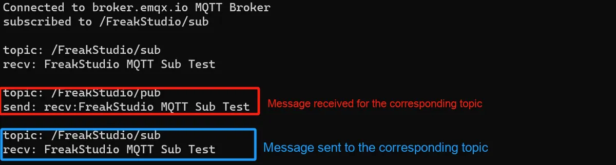
MQTTX The software displays the following messages:
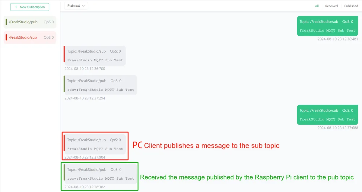
After sending ten times, the Raspberry Pi Client disconnects and terminates the program.
3.6.3 MQTT Client Subscription.mp4 24.1 MB
For more relevant routines, interested readers can refer to the following two links:
- Wiznet Official Documentation
https://docs.wiznet.io/Product/iEthernet/W5500/w5500-evb-pico
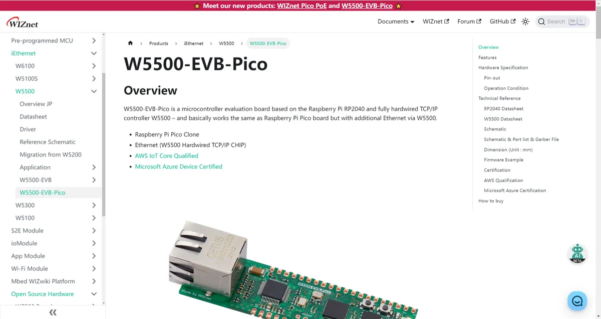
- Official sample program of Wiznet
https://github.com/Wiznet/RP2040-HAT-MicroPython/tree/main/examples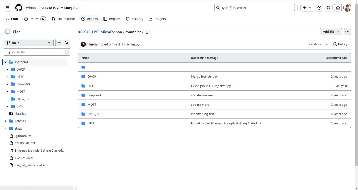
References
- Ethernet Wikipedia
https://en.wikipedia.org/wiki/Ethernet
- A Brief Talk on Ethernet: A Beginner’s Guide to Learning Ethernet
https://www.graniteriverlabs.com/zh-tw/technical-blog/ethernet-lan-test
- Ethernet is 40 years old
https://ajovomultja.hu/news/ethernet-40-years-old?
- Brief Discussion on the OSI Reference Model (Seven-Layer Model)
https://www.cnblogs.com/du-z/p/10799661.html
- What is the OSI model?
https://aws.amazon.com/cn/what-is/osi-model
- Plain-Language Explanation of the OSI Seven-Layer Network Model
https://www.freecodecamp.org/chinese/news/osi-model-networking-layers/
- Chapter 39 ETH—Lwip Ethernet Communication
https://www.cnblogs.com/firege/p/5805983.html
- Interface Protocol (IV): Ethernet Learning (I): Protocol
https://blog.csdn.net/qq_40483920/article/details/108262953
- IEEE 802.3 Ethernet Version 1.0 (January 2010)
- Introduction to Ethernet
https://networklessons.com/cisco/ccna-routing-switching-icnd1-100-105/introduction-to-ethernet
- Ethernet Basics and the IEEE 802.3 Standard
- W5500 Overview
https://docs.wiznet.io/Product/iEthernet/W5500/overview
- W5500 for Ethernet
https://gaoyichao.com/Xiaotu/?book=stm32
- Master the W5500 Ethernet Chip in One Article
https://blog.csdn.net/YinShiJiaW/article/details/102956975
- STM32 + W5500 Network Communication ------- Fundamentals of Embedded System Learning
https://www.cnblogs.com/lwtt/p/15731386.html
- STM32--W5500: A Beginner's Guide and Interpretation
https://blog.csdn.net/weixin_42066185/article/details/88413565
- W5500_Driver
https://github.com/caginagirdemir/W5500_Driver
- Python Development with W5100S/W5500 and RP2040
https://blog.csdn.net/wiznet2012/category_12531006.html
- WIZnet HK/ W5100S_W5500+RP2040 Micro Python Examples
https://gitee.com/wiznet-hk/W5100S_W5500_Micro_Python
- [Open Source] Serial/Bluetooth/TCP/UDP Debugging Tool SerialTest
https://www.cnblogs.com/wh201906/p/16622462.html
- 【Diao Ye Learns Programming】MicroPython Manual: MQTT Communication umqtt Module
https://blog.csdn.net/weixin_41659040/article/details/132822335
- micropython-umqtt.robust 1.0
https://pypi.org/project/micropython-umqtt.robust/
- MQTTX Desktop Client User Guide
https://www.emqx.com/zh/blog/mqtt-x-guideline
- What on earth is the MQTT protocol? This article will give you the answer!
https://juejin.cn/post/6976441705067184135
- A 10,000-Word In-Depth Guide: Principles and Practical Cases of MQTT
https://juejin.cn/post/7332331306212835365
- Getting Started with the MQTT Protocol: Basic Knowledge and Quick Tutorial
https://juejin.cn/post/7249205118532190269
- WIZnet HK/ W5100S_W5500+RP2040 Micro Python Examples
https://gitee.com/wiznet-hk/w5500-evb-pico-routine
- MQTT Protocol - Chinese Version
https://mcxiaoke.gitbooks.io/mqtt-cn/content/
Version Record
Version Number | Modifier | Time | Content |
v1.0.0 | Li Zisheng | 2025/09/18 | Initialize the document, based on MicroPython version V1.23.0. The section about serial port to Ethernet is not included in the document. |
v1.0.1 | Li Zisheng | 2025/12/05 | Some images have been modified. Initialize the document, based on MicroPython version V1.23.0. The section about serial port to Ethernet is not included in the document. |
v1.1.0 | Li Zisheng | 2025/12/15 | Initialize the document, based on MicroPython version V1.23.0. The section about serial port to Ethernet is not included in the document. |