
Contents
1. Hardware Explanation
1.1 Basics of USB (Universal Serial Bus)
Here, since the USB protocol is rather complex and covers a wide range of knowledge points, we will only explain the basic knowledge of the USB protocol to help you quickly form a general and macroscopic understanding of the USB (Universal Serial Bus).
1.1.1 Introduction to USB (Universal Serial Bus)
USB (Universal Serial Bus) is a widely adopted universal serial bus standard that provides a standardized data transmission interface between computer devices and peripherals. It is a Plug and Play bus standard, allowing users to connect and use various peripherals such as mice, keyboards, printers, scanners, etc. on a computer.
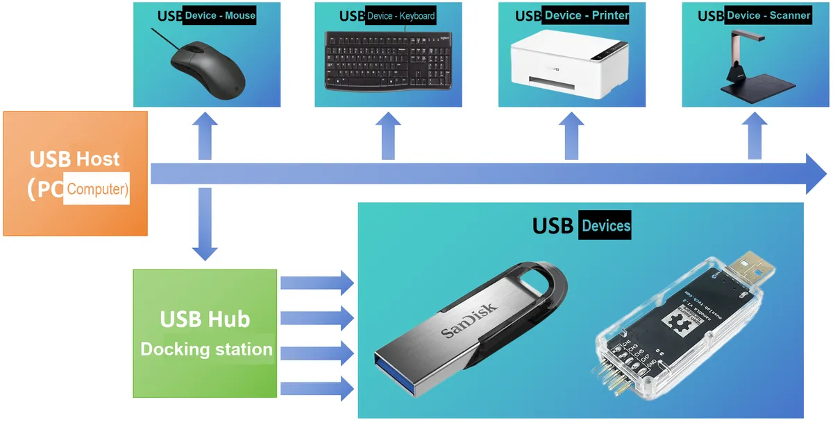
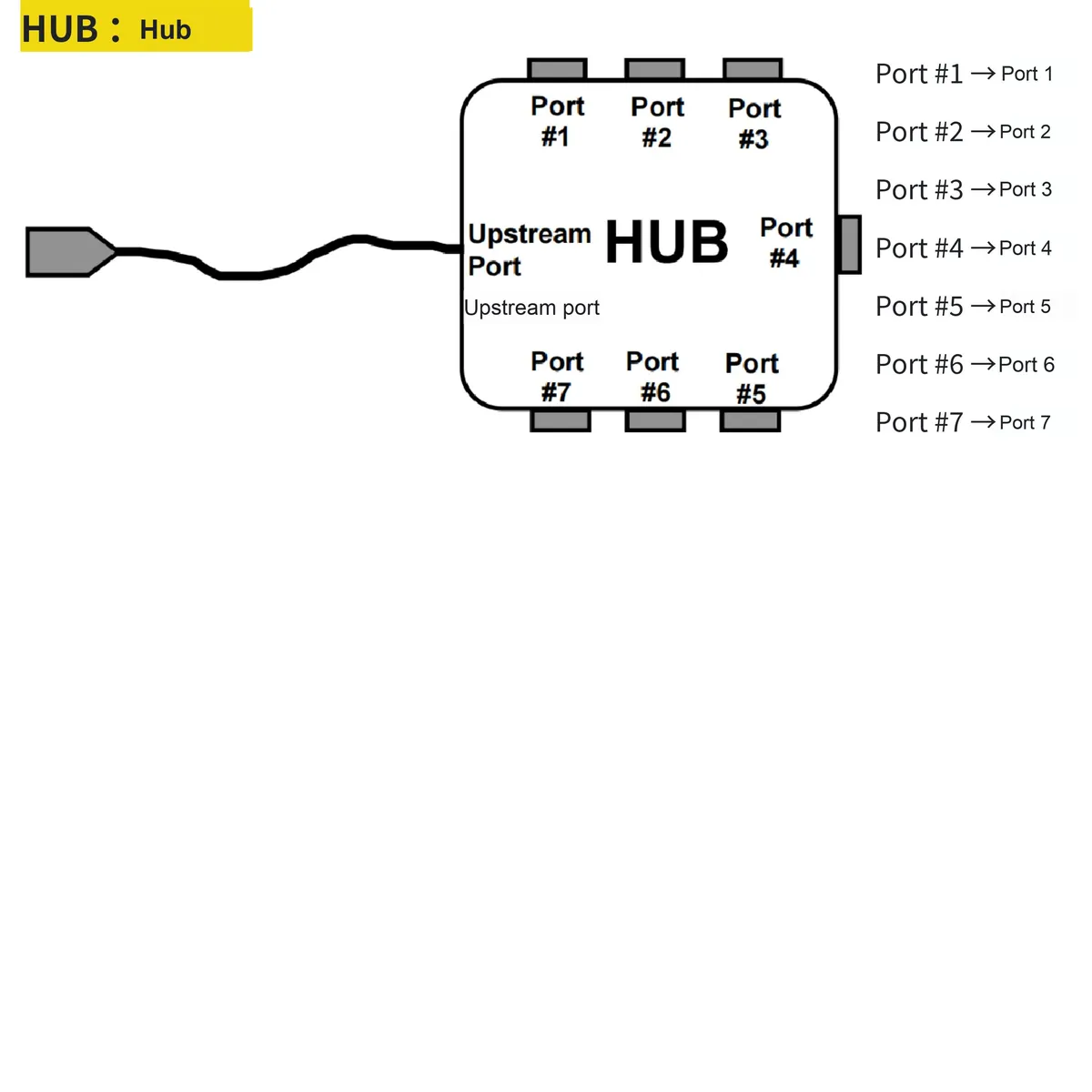
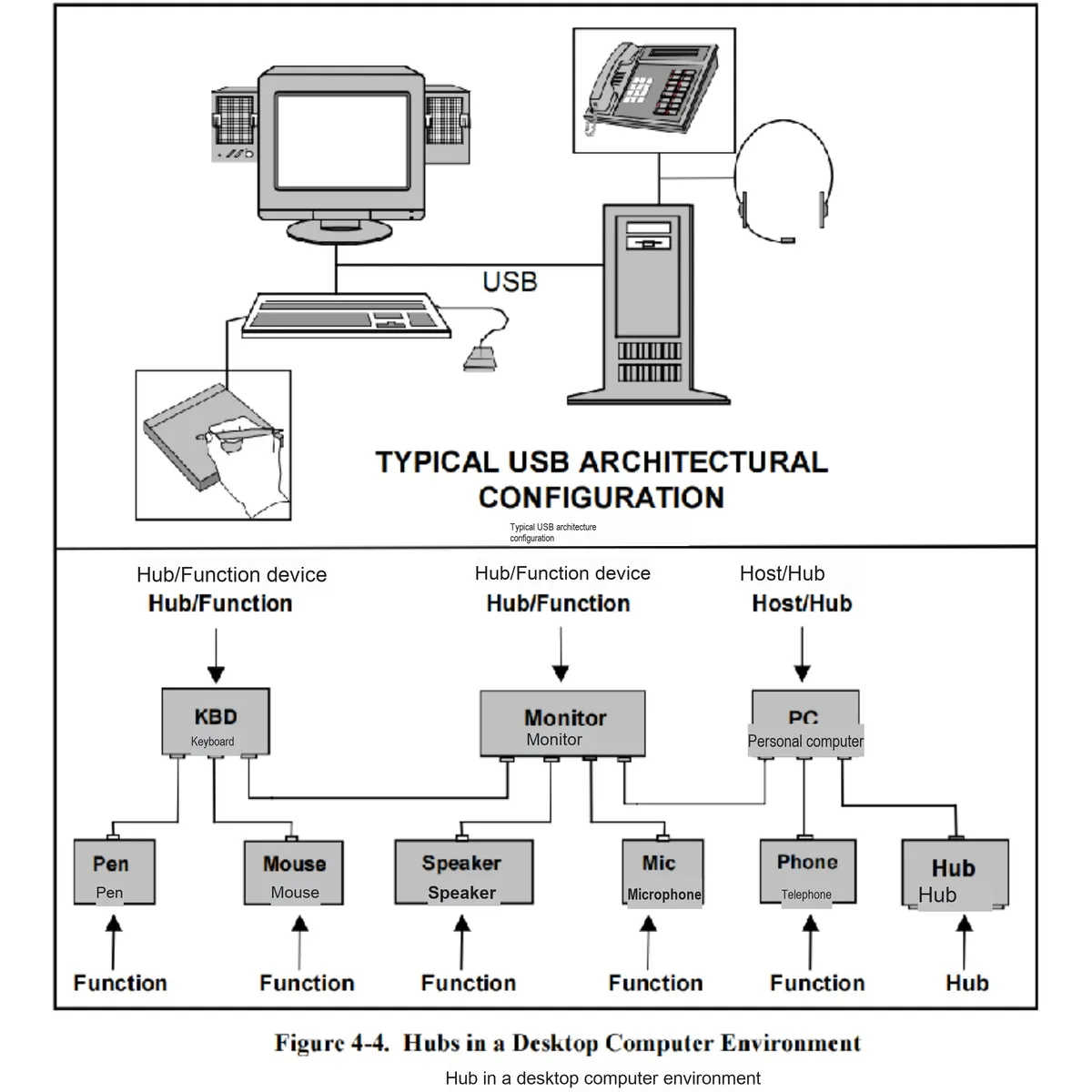
The USB connection adopts a master-slave architecture, where the host device controls and manages the entire USB system.
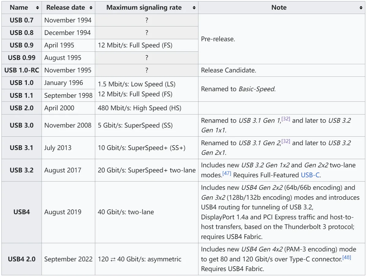
As of now, there are a total of four versions of the USB protocol:
- USB 1.0/1.1: Supports a maximum data transfer rate of 12 Mbps
- USB 2.0: Supports a maximum data transfer rate of 480Mbps
- USB 3.x: includes USB 3.0, 3.1 and 3.2, and supports a maximum data transfer speed of 10Gbps
- USB4: Supports a maximum data transfer speed of 40Gbps and is compatible with the Thunderbolt 3 protocol
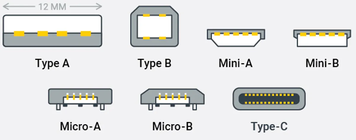
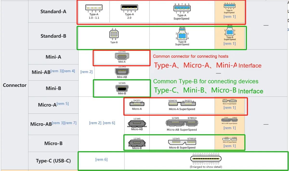
The three most common electrical connectors that apply the USB protocol in our daily lives are as follows:
- USB Type-A: The most common standard USB interface, used for host devices
- USB Type-B: Used for peripheral devices such as printers, scanners, etc.
- USB Type-C: features a symmetrical design, supports reversible plugging, and delivers higher power transmission capability
1.1.2 Development History of USB Protocol
On early PCs, there were serial ports and parallel ports, and even mice, keyboards, and game controllers had dedicated interfaces. Moreover, none of these interfaces supported hot-swapping, meaning devices had to be plugged in before the PC was powered on to function properly. In addition, these various interfaces also consumed valuable CPU resources, such as hardware interrupts and DMA channels.
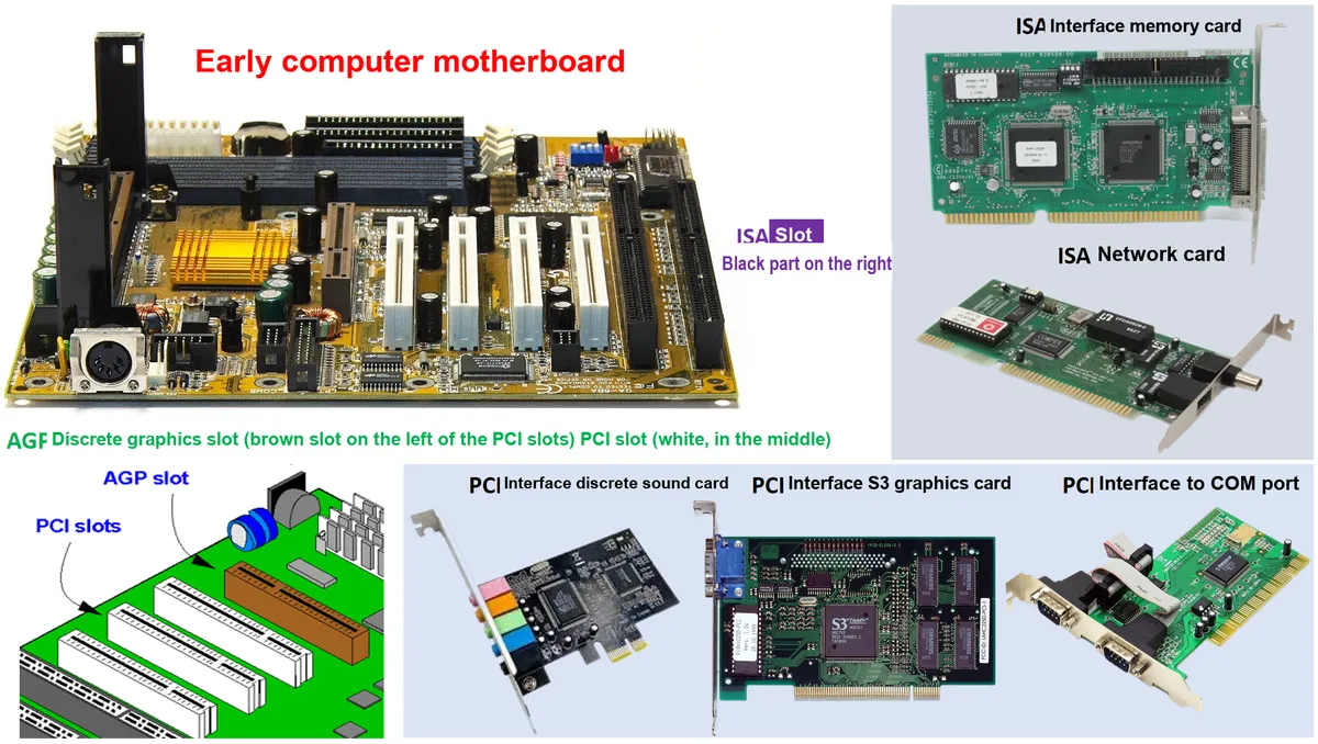
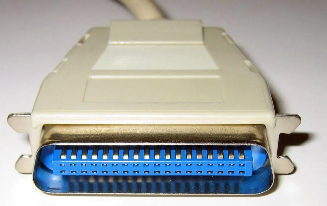
To address these issues, Ajay Bhatt put forward the concept of the Universal Serial Bus, namely USB. One of the core design philosophies of USB is to provide a unified solution for the various interfaces on PCs while replacing the numerous and diverse interfaces and slots on computer motherboards.

Ajay Bhatt and his team worked on joint R&D at Intel alongside six other companies including IBM, Microsoft, DEC, NEC, Compaq and Nortel. Eventually in 1995, the first USB-supporting integrated circuit was manufactured by Intel, and the first commercially available USB 1.0 RRC standard was released in November 1995. At the same time, the seven companies jointly founded the non-profit organization USB-IF (USB Implementers Forum).Prior to this, USB 0.8, USB 0.9 and USB 0.99 were released as "pre-release versions" that same year, but had not yet been put into commercial use.

USB 1.0 offers two communication rate modes:
- Low-speed version (Low Speed): The communication rate is 1.5 Mb/s
- Full Speed Version: The communication rate is 12 Mb/s
USB 1.0 supports Self-Adaptation configuration, which can automatically adapt to peripheral devices without users changing device settings. This interface also supports hot-swapping, so devices can be replaced without restarting the host. Although it was the first commercial version of USB, it was not widely accepted by the market, and there were very few devices available for consumers.
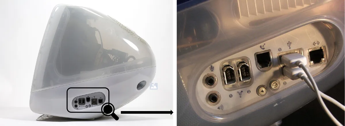
Interestingly, although Intel was the first company to invest in USB technology, the world's first product to adopt USB technology was not developed by Intel (but the world's first USB-compatible integrated circuit was manufactured by Intel, so please note the distinction!). The world's first product to feature USB technology was Apple's iMac G3, released in 1998, which conformed to the USB 1.1 standard established that same year.
As the market demands higher compatibility for PCs and their various peripherals, and applications become increasingly complex, the requirements for data transfer rates have gradually risen. USB 2.0 was released in April 2000; in addition to being compatible with USB 1.x full-speed signal transmission, it also added an operating mode that supports a higher maximum signal transmission rate of 480 Mbit/s, which is referred to as High Speed.USB 2.0 also provides Plug and Play functionality for multimedia and storage devices, and supports power supply via USB connectors with ratings up to 5 V and 500 mA.
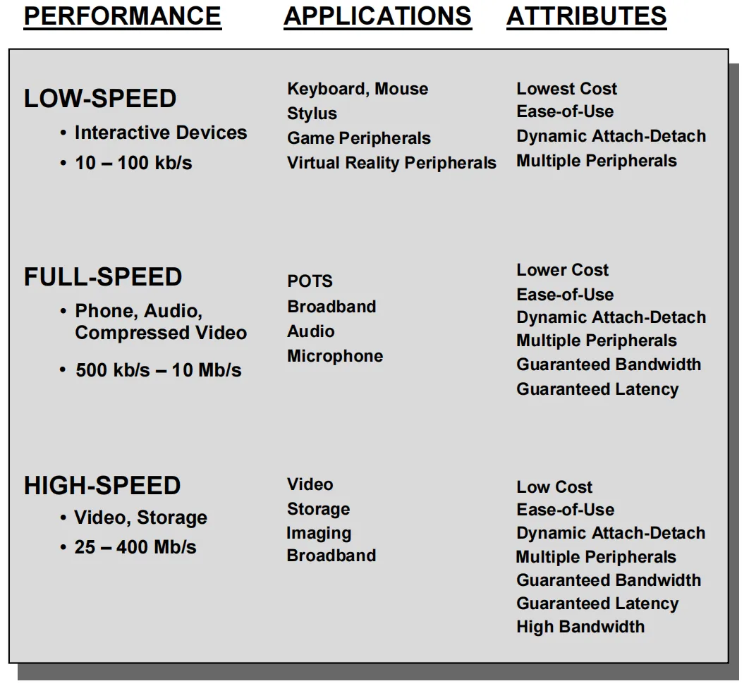
To meet the growing demand for communication rates, the USB Implementers Forum (USB-IF) introduced the USB 3.0 standard in 2008, which supports a data rate of up to 5 Gbit/s and is referred to as the SuperSpeed mode. Subsequent iterations include the SuperSpeed+ mode and SuperSpeed++ mode, which offer theoretical maximum data rates of 10 Gbit/s and 20 Gbit/s respectively.
For the communication rates and feature changes of various USB versions, please refer to the table below:
1.1.3 Overview of USB System
The USB system is a master-slave communication system with a "tiered star topology" structure, which consists of one host and up to 127 peripherals (also referred to as Devices or Peripherals).
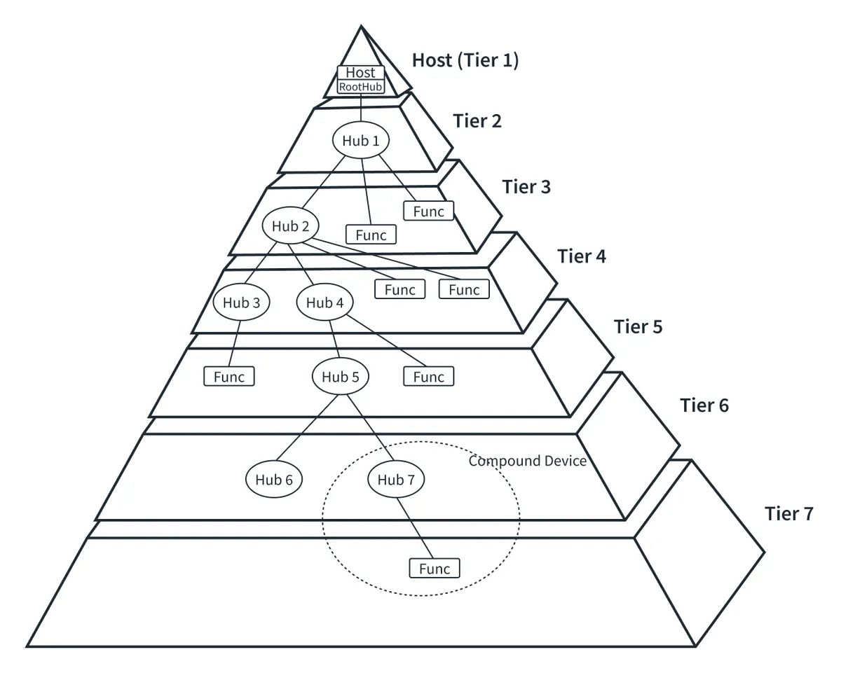
Peripherals fall into two categories: functional peripherals (Functions) and hubs (HUBs):
- Function Peripheral (Functions): A device that cannot mount other USB devices; common examples include mice, keyboards, and other such peripherals.
- Hub (HUB): A peripheral device that expands the capability of USB interfaces, which can be connected with functional peripherals as well as other hubs.
By cascading hubs (connecting a hub to another hub), you can expand the number of peripherals that can be connected, ultimately forming a pyramid structure as shown in the left figure. At the top of the pyramid are the host and the root hub, which can be connected to functional peripherals or other hubs. Extending downward layer by layer, this forms a hierarchical star connection topology, which is the so-called "Tiered star topology". The protocol specifies a maximum of 7 network layers, which corresponds to the cascading of up to 5 hubs.
USB adopts a polling broadcast mechanism for data transmission, all transfers are initiated by the host, and only one data packet is allowed to be transmitted at the same time. Devices are distinguished by 7-bit bus addresses, among which address 0 is reserved and unavailable to users for devices without assigned addresses, so a host can support up to 127 devices.
After a peripheral is connected to the bus, it must first undergo an enumeration operation before it can be used. On the one hand, the enumeration operation is to assign an address as mentioned above; on the other hand, it obtains the device descriptor to confirm information such as the device type and manufacturer, so that the host can select the corresponding driver. In the USB protocol, functional devices are further subdivided according to their different functions, such as HID, CDC, etc. , which will be described in detail in subsequent introductions.
We have already mentioned that all communications over USB are initiated by the host. This means that no two devices can communicate directly with each other. Even if a device has data to send to the host, it must wait for the host's command. However, there is an exception: when a device is placed in the "Suspend" state by the host, the device can send a "remote wakeup" signal to the bus.
Early USB systems were generally used for peripheral expansion of PCs, so the host was usually a PC, and any device connected to a PC was a peripheral. With the rise of smart devices, or handheld devices as they are also called, a demand has emerged that such devices should be able to connect to a PC as a peripheral and also expand via the USB system as a host. This gave rise to the so-called OTG (On The Go) devices, which have made some adjustments in physical wiring and Communication Protocol, enabling the device to switch between host and slave roles.
Generally speaking, USB interfaces are very convenient to use, as they provide a unified interface for various peripheral devices. However, due to their versatility, the corresponding protocols are relatively complex and involve a wide range of aspects. A brief introduction to each aspect is given below.
1.1.4 USB Physical Interface
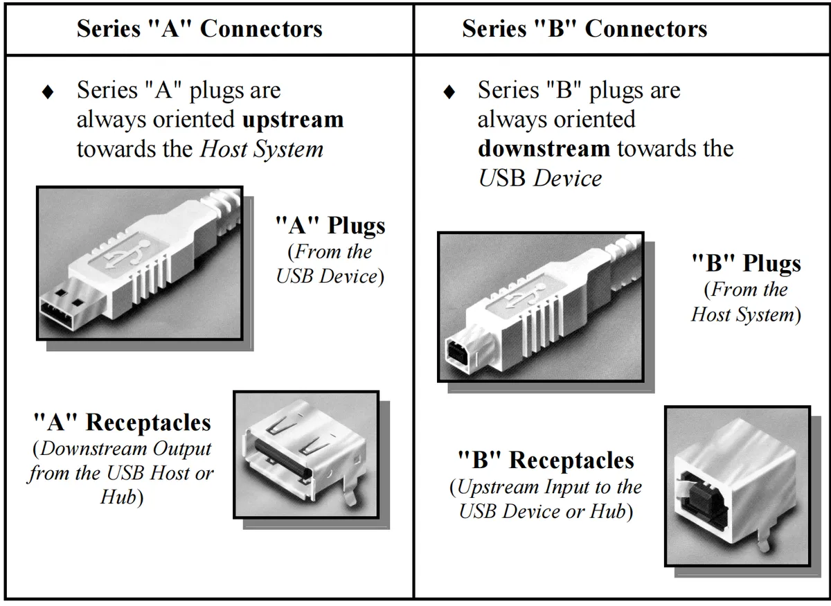
Since USB is a master-slave architecture system, it always establishes a connection between a host and a peripheral. To prevent incorrect cabling, the connectors at the two ends of a USB cable are necessarily different. The connector plugged into the host side is generally referred to as a Type-A connector, while the one on the peripheral side is a Type-B connector.
The figure below lists some common USB connectors.
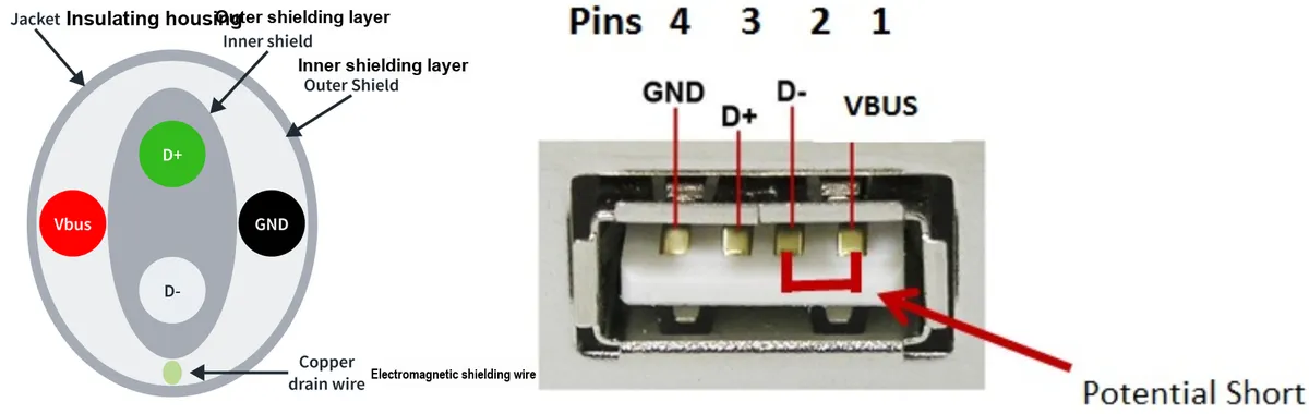
Standard USB 2.0 ports and cables all feature a 4-wire design: VBUS and GND serve as the power line and ground line respectively, used to supply power to certain USB devices. VBUS typically provides a voltage of 5V, while D+ and D- form a pair of differential twisted pairs for data transmission – this is somewhat similar to the RS-485 serial port we mentioned in serial communication, except that the voltage levels on the lines differ. The advantage of using differential signals is that these signals are less susceptible to electromagnetic interference from surrounding devices.They also do not emit any electromagnetic radiation that could interfere with nearby electronic devices, which is particularly important as the USB protocol is designed to operate around sensitive components such as microprocessors and microcontrollers.
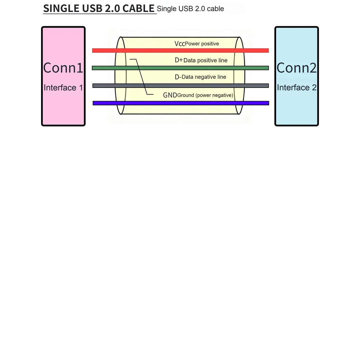
Later, for USB OTG devices, Mini connectors and Micro connectors were introduced, with cables and connectors evolving from the original four-wire configuration to a five-wire setup. The additional wire is labeled as the ID signal line, which is used to distinguish the identity of the device:
- When the ID line is grounded: it indicates that the initial identity of the device is a host, which is a Class A device
- When the ID line is left floating or connected to a high level: it indicates that the initial identity of the device is a device, which is a Class B device
A USB host can supply power to a device via the VBUS line on the cable, and devices can be categorized into the following two types according to whether they require current supply from the host: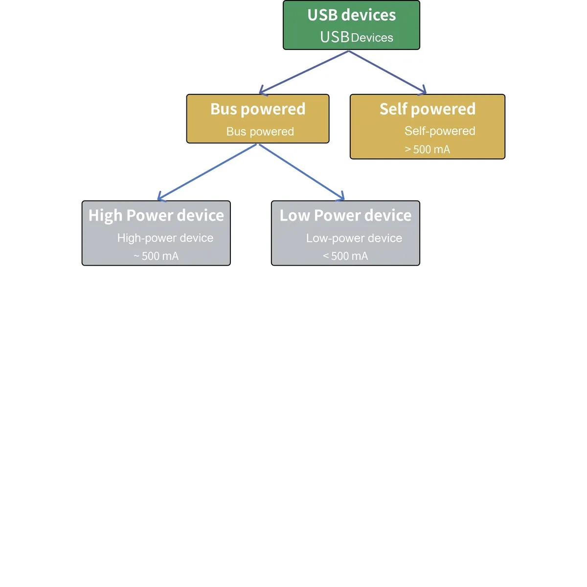
- "bus-powered" device: A device that draws current from the VBUS is referred to as a "bus-powered" device, and this category can be further divided into high-power devices and low-power devices:
- High-power devices: devices that require a current of approximately 500mA
- Low-power devices: devices that require a current of less than 500 ms
- "self-powered" device: A device that selects its own power supply is referred to as a "self-powered" device
It should be noted that the device cannot supply power to the host, which means that the VBUS line of the device cannot sink current to the bus.
USB is a communication bus that supports hot-plugging. In the USB protocol, the Host can determine whether a device is plugged in by detecting the level changes of the D+ and D- lines: After a USB device is connected, it will pull the two signal lines D+ and D- to a specific level combination; the host will monitor the level states of the D+ and D- lines, and identify the type of the connected device according to different level combinations.
Let's take a look at a common circuit diagram for the connection between a host and a device:
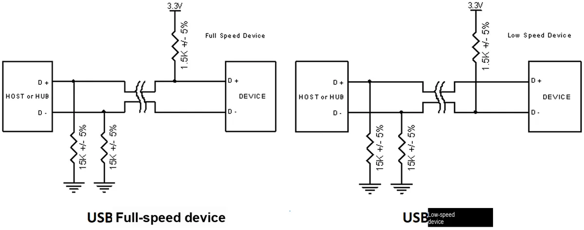
It can be seen that on the ports of the host or hub, the D+ and D- differential signal lines are both pulled down to ground via a 1.5K resistor.
For USB devices, there are two scenarios:
- For low-speed devices: the D- signal line is pulled up with a 1.5K resistor
- For high-speed/full-speed devices: a 1.5K pull-up resistor is connected to the D+ signal line
When a device is plugged into a port, the voltage level on the signal line connected to the pull-up resistor is divided by the pull-up and pull-down resistors, which appears as a high-level signal to the connector. The hub then detects that a device has been inserted, and reports this signal to the host either directly or via an upstream hub. The host then determines the communication speed of the newly inserted device based on the voltage level on the D+ or D- line.
For high-speed devices, the host will first identify them as full-speed devices by default, and then switch them to the high-speed mode through further data interaction with the devices.
1.1.5 USB Communication Hierarchy
The USB protocol consists of multiple layers, mainly including the following layers:
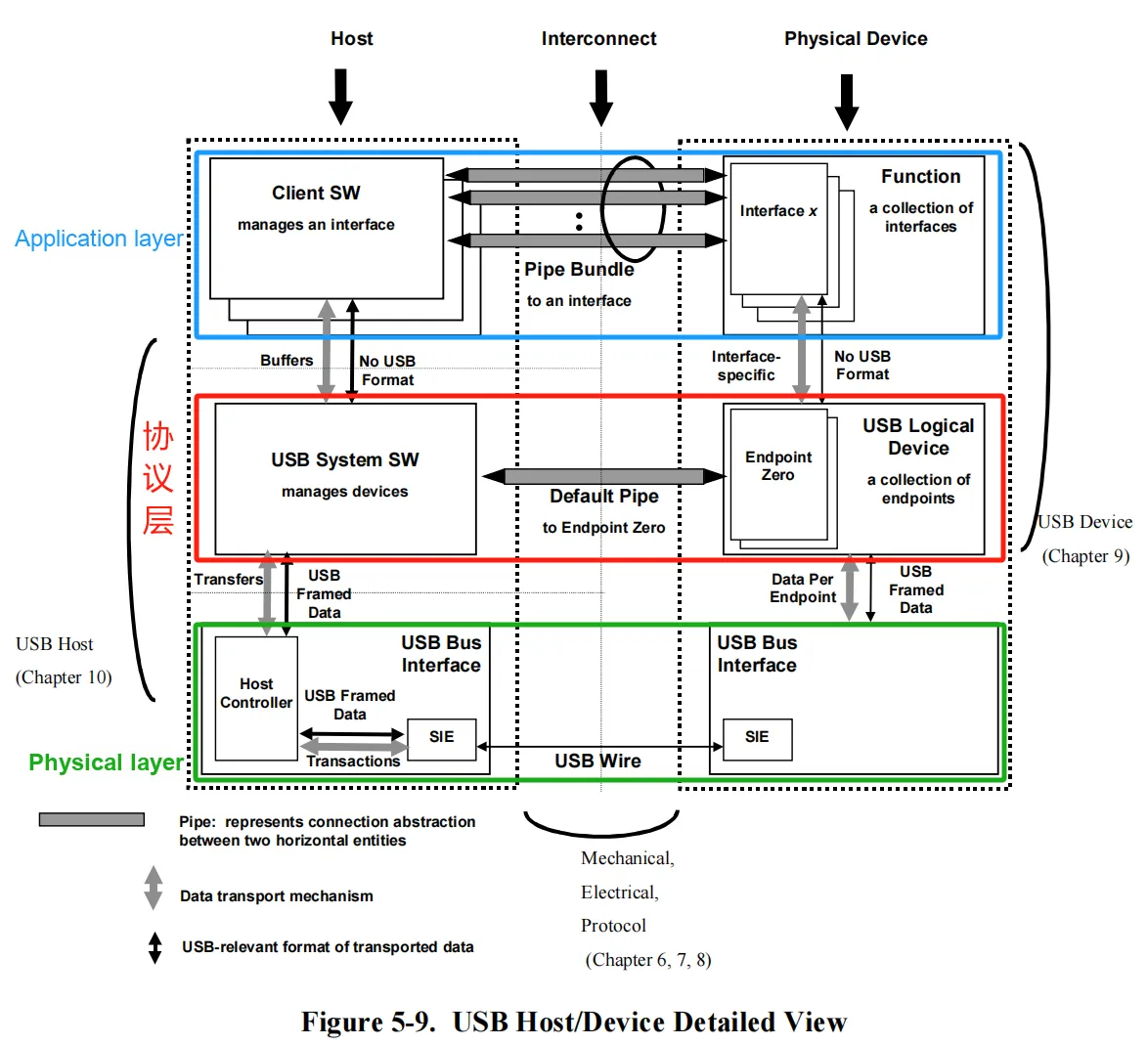
From the bottom layer to the top layer, they are as follows:
- Application Layer Function Layer:
- This layer is responsible for implementing the application functions of USB devices.
- It defines the specific functions and behaviors of different types of devices, such as mice, keyboards, scanners, etc.
- Abstract the functions of a device into interfaces. Users can directly access these functional interfaces via drivers or client software (Client SW) to fulfill specific application requirements, which enhances the scalability and interoperability of USB devices.
- Different interfaces can encapsulate different device functions, such as keyboards, mice, audio devices, etc. Users can select appropriate interfaces to access and use according to actual needs.
- Protocol Layer USB Device Layer:
- This layer is responsible for the logical control and data transmission of USB devices. The client software (Client SW) converts the requests and content for sending and receiving data from the client software into USB transmission transactions through the protocol layer.
- It defines functions such as enumeration, configuration, and endpoint management for USB devices, as well as the implementation of different transfer types (control, bulk, interrupt, and isochronous).
- This layer provides a standardized USB device interface, shielding the underlying physical details.
- A USB device is composed of several endpoints, which are the smallest objects of communication logic on a USB device.
- Each endpoint can be used for different data transmission purposes, such as control, interrupt, bulk or isochronous transmission. Generally, a device has one control endpoint for transmitting device configuration and status information, while the other endpoints are used for data transmission and reception.
- The host's driver or user program will establish logical pipes with these endpoints, and data is transmitted and received through the pipes, thus forming independent data channels.
- Physical Layer USB Bus Interface Layer:
- This layer is responsible for implementing the USB physical interface, including basic functions such as electrical characteristics, connectors, and signal transmission.
- It defines the physical characteristics of the USB bus and serves as the foundation for USB communication.
- The host needs to continuously query (polling) the devices connected to the USB bus to detect new devices and perform operations such as enumeration and configuration. Meanwhile, it also needs to schedule data transmission among multiple devices to ensure that each device can access the bus fairly.
- On the device side, it is necessary to identify and filter the data packets on the bus, and route them to the corresponding endpoints. Different types of endpoints (control, interrupt, bulk, isochronous) have different requirements for transmission characteristics.
- These complex low-level protocol interactions are all handled by the USB driver of the operating system and the physical layer processing module (such as the PHY chip) on the device side, which is transparent to upper-layer application programs and driver programs.
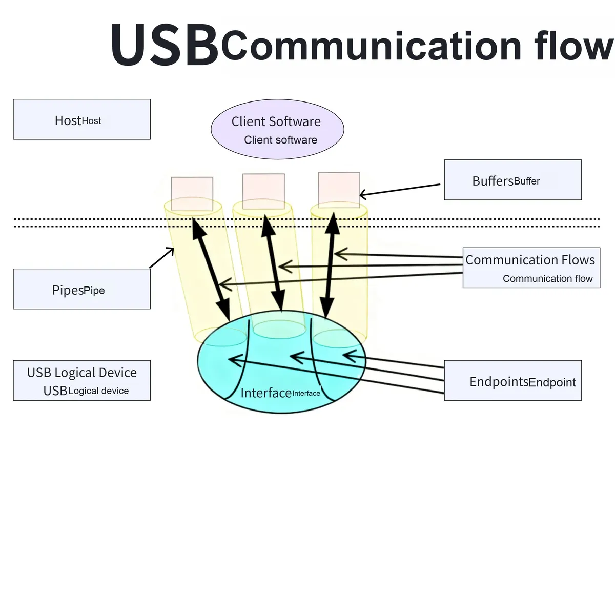
These three layers have a clear division of labor and together form a complete USB communication system:
- The physical layer provides the underlying hardware interface
- The protocol layer implements data transmission in compliance with the USB protocol.
- The application layer implements specific functions for different device types.
This layered design endows the USB system with excellent scalability and portability: new devices only need to be developed at the application layer, without the need to modify the underlying physical and logic implementations.
USB PHY Chip
USB Phy chip is a dedicated integrated circuit chip that implements the functions of the USB physical layer, and it mainly includes the following functions:
- Electrical interface: Provides the electrical characteristics required by physical layer specifications such as voltage, current and impedance for USB data cables.
- Signal encoding/decoding: Encode the digital data sent by the host or device into analog signals that comply with the USB physical layer standards, and decode and restore the digital data at the receiving end.
- Clock Recovery and Synchronization: Recover the clock signal from the received data stream to ensure that the transmitter and the receiver remain synchronized.
- Differential signal transmission: Data is transmitted using differential signal technology to suppress common-mode interference and improve anti-interference capability.
- Hot-swap support: Provides hot-swap detection and connection functions, and supports Plug and Play for devices.
- Power management: controls the power supply of USB devices, including overcurrent protection, short-circuit protection, etc.
USB Phy chip is a core component for physical layer communication between USB devices and hosts. It implements all physical layer requirements specified in the USB standards, ensuring the reliable operation of the entire USB system. Major suppliers of mainstream USB Phy chips include Microchip, Texas Instruments, and Cypress.
1.1.6 USB Communication Endpoints and Endpoint Descriptors
An endpoint is the most basic unit for communication between a USB device and the host. Logically, each USB device consists of multiple independent endpoints: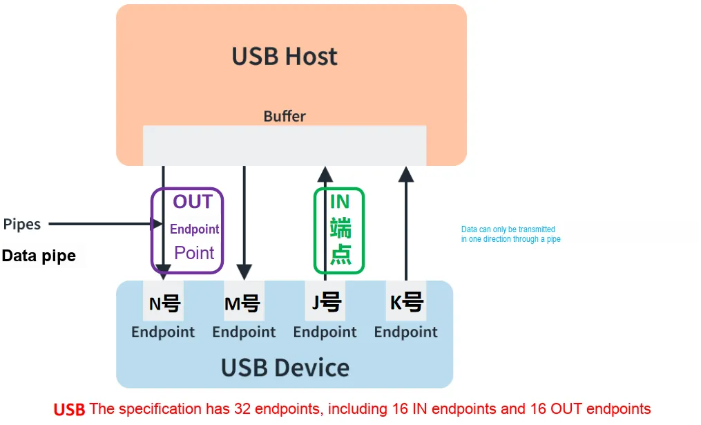
- Each endpoint is assigned a unique endpoint number during device design, and there is no need to negotiate with the host when the device is connected;
- Based on the direction of data transmission, endpoints are classified into output endpoints (used to receive data from the host) and input endpoints (used to send data to the host), and this classification is made from the perspective of the host;
- An endpoint can only have a single transmission direction, which is determined during device design.
- When a USB device is connected, it negotiates with the host to obtain an address. An endpoint for communication can be uniquely identified by the device address, endpoint number and transfer direction.
Endpoints in the USB protocol support four transfer modes:
- Bulk Transfer:
- Asynchronous Transfer Mode
- No time limit
- It can transmit data in any format and of any length.
- It is used to transmit non-urgent data that requires large bandwidth.
- Interrupt Transfer:
- Asynchronous Transfer Mode
- time-limited
- Small Data Volume Transmission
- Used to transmit data that requires timely response
- Control Transfer:
- Asynchronous Transfer Mode
- time-limited
- Used for control operations such as device configuration and status query
- Isochronous Transmission:
- Synchronous Transmission Mode
- time-limited
- Error retransmission upon failure is not supported.
- It is used to transmit time-sensitive data that can tolerate packet loss, such as audio and video streams.
It should be noted that every USB device has a set of default endpoints operating in control transfer mode, which are used to transmit configuration and control information. These are the OUT and IN endpoints with endpoint number 0. When a USB device is first plugged in and has not yet been assigned an address, the host can only access endpoint 0 via bus address 0. At this point, the communication capability of the USB device is limited; only after the host obtains the device descriptor through endpoint 0 and completes the enumeration operation can the device communicate with the host normally.
Each endpoint has different operating modes and limitations, and this information needs to be notified to the host during the device enumeration process. The descriptor that describes the operating modes and limitations of an endpoint is called an Endpoint Descriptor, which records the following key information about the endpoint:
- Endpoint ID
- Endpoint query frequency
- Transmission modes (batch, interrupt, synchronous, etc.)
- Maximum Data Packet Length
Through endpoint descriptors, the host can learn the specific characteristics of each endpoint, so as to correctly communicate and exchange data with them.
1.1.7 USB Enumeration Process, Descriptors and USB Device States
When a USB device is plugged into a host, it needs to go through an enumeration process, which mainly includes the following steps:
- After detecting the connection of a new USB device, the host will query the basic information of the device, such as the vendor ID, product ID, etc.
- The device provides the host with a series of Device Descriptors, which describe its own type, functions, endpoint information and other relevant details.
- The host identifies the device type based on these descriptor information and selects the appropriate USB device driver.
- The host also assigns addresses to devices and configures them to bring them into working condition.
- Finally, the application can access the functions provided by the device by calling the USB driver interface of the operating system.
Every USB device has exactly one Device Descriptor, which defines information such as the USB version number used by the device, the device class code, device subclass code, protocol code, vendor information, and the number of possible configurations. A USB device can have multiple configurations, but only one can be active at a time.
Each configuration of a USB device corresponds to a Configuration Descriptor, which defines information such as the device's power supply mode and the number of supported interfaces. A USB device can support multiple interfaces, and USB devices with multiple interfaces can be divided into two types:
- USB Compound Device (Composite Device):
- A physical USB device contains multiple functional interfaces.
- Each interface can be used independently. For example, an audio device includes interfaces such as audio control, audio stream, and MIDI stream.
- The host operating system manages and accesses each interface as an independent logical device.
- The composite device needs to provide complete descriptor information, including the descriptor for each interface
- USB Composite Device (Composite Device):
- Multiple physically independent USB devices (such as keyboards and mice) are combined and connected to the host as an integrated device.
- The host operating system manages the entire composite device as a single logical device.
- The descriptor information of a composite device is also holistic and cannot be split into independent interfaces.
- The individual physical devices that make up a composite device are typically interconnected and share certain hardware resources.
Taking the common USB composite device, the USB audio device, as an example, it usually includes the following interfaces:
- Audio control interface - used for the configuration and control of audio devices
- Audio stream interface - used for transmitting PCM audio data
- MIDI Stream Interface - Used to transmit music data conforming to the MIDI protocol
In USB devices, the Interface Descriptor is used to describe interface information, which includes the following types:
- Interface Type (Class), Subtype (SubClass) and Protocol (Protocol)
- Used to identify the function type of the interface, such as HID, audio, video, etc.
- Endpoint information used by the interface
- It describes the number of endpoints used by the interface, endpoint types (control, interrupt, bulk, isochronous), etc.
- Interface Numbering and Settings
- The interface number is used to identify the uniqueness of the interface.
- Interface settings describe the different operating configurations of an interface.
It should be noted that one interface may involve multiple endpoints, and each endpoint has one endpoint descriptor.
As we mentioned above regarding the types and subtypes of interfaces, in fact, to facilitate the management and access of different types of USB devices, the USB protocol defines a series of device classes and subclasses, and the main types of USB devices are as follows:
- Human Interface Device (HID)
- including input devices such as mice, keyboards, and gamepads
- Data interaction is performed using a simple and standard HID protocol
- Mass Storage Device (Mass Storage Class, MSC)
- including storage devices such as USB flash drives and portable hard drives
- Data transmission using the mass storage device protocol
- Communication Device Class (CDC)
- including communication devices such as USB serial ports and modems
- Use communication device protocols for data exchange
- Audio Device (Audio Class)
- including audio devices such as USB microphones and speakers
- Data transmission using audio device protocols
- Video Device (Video Class)
- including USB cameras and video capture devices
- Data transmission using video device protocol
- Printing Device (Printer Class)
- including USB printers
- Use the printer device protocol for data exchange
- Smart Card Device (Smart Card Class)
- including USB smart card reader
- Data transmission using smart card device protocols
The classification of these classes is reflected in the class, subclass and protocol-related fields of the device descriptor and interface descriptor, mainly the interface descriptor:
- Device Class
- It is used to identify the major type of a device, such as HID (Human Interface Device), CDC (Communication Device), Mass Storage, etc.
- Subclass (SubClass)
- It is used to further subdivide the types of devices, such as mice, keyboards, gamepads, etc. under the HID class.
- Protocol
- Describe the specific protocols supported by the device, such as USB HID under the HID class, serial port protocol under the CDC class, etc.
The host selects a driver based on the information of these device types and the vendor information mentioned in the device descriptor.
The USB protocol specifies that USB devices have six operating states:
- Unconfigured State: This is the initial state of a USB device immediately after it is connected to the host. In this state, the device has not been assigned an address and cannot perform any communication.
- Address State: After a device is identified and assigned a unique address, it enters the address state, in which the device can communicate with the host using the assigned address.
- Configured State: When a device sends a configuration request to the host and the host accepts the request, the device enters the configured state. In this state, the device has completed all configuration processes, including setting endpoints, acquiring descriptors, etc. , and can start data transmission with the host.
- Suspended State: When a device has no data transmission for a certain period of time, it will automatically enter the suspended state to save power. In this state, the power supply of the device will be turned off, and the device will remain in the suspended state all the time unless an interrupt event occurs.
- Default State: refers to the status where the device has been powered on and completed reset, but not yet assigned an address; the host can access the device via the default address 0 and assign an address to it.
- Powered State: refers to the state where the device is already connected and receives power supply from the USB bus
These state transition processes correspond to the enumeration process of the USB device, and the host will perform corresponding operations and configurations according to the current state of the device until the device is fully initialized and ready.
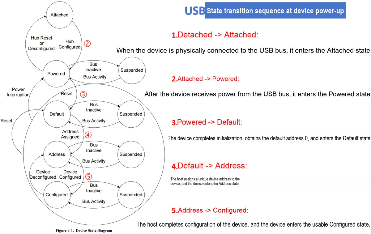
It should be noted that if the device loses connection with the host in any state, it will return to the Detached state. This state transition mechanism ensures that USB devices can be safely plugged, unplugged and managed.
When we plug a USB device into an available port on a PC, the PC needs to go through a series of operations to assign an address to the device, negotiate and select the appropriate device driver, and perform necessary configuration for the USB device. This process is what we refer to as the enumeration process, the details of which are as follows:
- Device Connection Detection
- Due to the hot-swap design of USB connectors, inserting a USB device into a port of the HUB will change the connection status of the HUB.
- When the host queries the HUB, the status notification sent by the HUB indicates that the device has been connected.
- At this point, the host becomes aware of the port where the newly inserted device is located
- Port Reset
- The host shall wait for at least 100ms until the device is fully inserted and the power supply becomes stable
- The host sends commands to the HUB to enable and reset the ports, putting the device into the Default state.
- The device draws no more than 100 mA from the VBUS pin to complete basic function configuration.
- The host can access the device via the default address 0
- Get Device Descriptor
- The host communicates with endpoint 0 of the device by accessing the device via address 0
- Get device descriptor information
- Select Configuration
- The host selects an appropriate configuration based on the device descriptor information
- Assign Address
- The host assigns a unique device address to the device.
- Load the driver
- The host selects and loads the appropriate USB driver based on the device information.
- The device enters the Configured state
- Set up interface
- The host initializes and configures each interface of the device.
- Device ready
- So far, the enumeration process of the USB device is completed, and the device enters the available state.
1.1.8 USB Data Transmission and Data Packets
1.1.8.1 USB Data Transmission
USB is an asynchronous serial communication method (the USB 2.0 protocol adopts half-duplex communication), meaning that only one data packet is transmitted on the bus at any given time. On the USB bus, data is transmitted in little-endian order, that is, the least significant bit is sent first, followed by the most significant bit.
The data signal lines on USB use a pair of differential signals, namely signal D+ and signal D-, which can represent two types of data:
- Diff. 1: When D+ is at a high level and D- is at a low level, this data is referred to as "Differential 1".
- Diff.0: When D+ is at a low level and D- is at a high level, this data is referred to as "differential 0"
Diff.1 and Diff.0 are the differential signals at the physical layer of USB signals. In terms of the represented data, the data adopts the NRZI (Non-Return-to-Zero Inverted) encoding scheme:
- When the NRZI encoded data is '0': the differential signal level flips and the differential data changes
- When the NRZI encoded data is '1': the differential signal maintains its level, and the differential data remains unchanged

It should be noted the relationship between differential data and NRZI encoded data: when USB transmits "data 0", the physical layer will generate "diff.0" differential data, but the "diff.0" signal does not necessarily represent "data 0", and it may also be a level transition in NRZI encoding.
If a large number of '1' s are transmitted consecutively on the bus, the level will not transition for a long time, which is detrimental to clock synchronization between the master and slave devices (the USB protocol does not have a separate clock line). Therefore, the USB protocol specifies the following mechanism: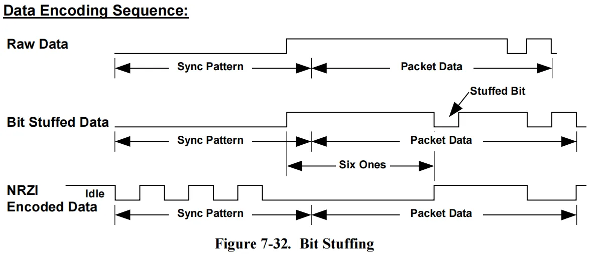
- Bit Stuffing:
- When six consecutive "1" s appear on the USB data line, a "0" bit will be forcibly inserted as a synchronization signal.
- This bit stuffing operation can ensure level transitions, and the receiving end uses this synchronization code to synchronize its own receiving clock to keep it consistent with that of the transmitting end.
- Receiver de-stuffing:
- When the receiving end decodes data, it needs to identify and remove these padded "0" bits.
- Users do not need to perform this operation, as it is implemented by the chip.
- the original data sequence can be restored
1.1.8.2 USB Data Packets
On the USB bus, the basic unit of data transmission is the packet, which consists of multiple distinct fields, specifically including:
- Synchronization Domain (SYNC)

- Used to help the receiver synchronize clocks and data
- It consists of a set of 0 data and one 1 data, and the set of 0 data will cause the level on the bus to flip continuously
- According to NRZI encoding, the receiving end can synchronize its clock with the transmitting end based on the frequency of level transitions.
- Full-speed/low-speed devices send 7 zeros, while high-speed devices send 31 zeros
- Packet Identifier (PID)
- Identifies the type of the current data packet, such as TOKEN, DATA, HANDSHAKE, etc.
- The PID consists of 8 bits of data, but we only use the lower 4 bits of them; the upper 4 bits are the complement of the lower 4 bits and are used for verification.
- other domains
- Depending on the type of data packet, it may contain other fields such as address, data payload, checksum, etc.
- End of Packet (EOP)
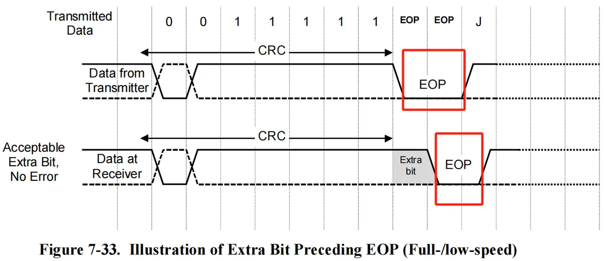
- Indicates the end of the current data packet
- Full-speed and low-speed devices simultaneously hold both the D+ and D- lines at the low level for two data bits, which corresponds to the SE0 signal for two data bit periods.
- High-speed devices use bit stuffing error signals, and the host needs to check the CRC check bits:
- If the check passes, this is the end-of-packet delimiter for the EOP packet
- If it does not pass, it is a bit stuffing error
Any packet starts with a synchronization field and a PID (Packet Identifier), and ends with an EOP (End Of Packet).
These different fields constitute the standard format of USB data packets. According to the different purposes of data packets, the USB protocol defines multiple types of data packets, such as:
- Token Packet
- Contains address and endpoint information, used to identify the target of data transmission
- including types such as OUT, IN, SETUP, etc.
- Data Packet
- transmit the actual data
- including two types of data packets: DATA0 and DATA1
- Handshake Packet
- It is used to transmit transmission status information, such as ACK, NAK, STALL, etc.
- Special Packet
- including special-purpose data packets such as SOF (Start of Frame), RESET, and SPLIT to implement special functions including synchronization and reset
The specific data packet specifications are shown in the following table:
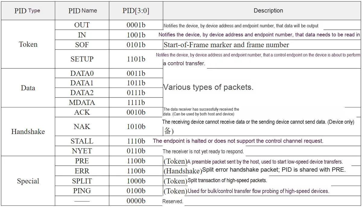
Next, we will introduce each data packet one by one.
1. Token Packet
In a USB system, all data transfer transactions are initiated by the host sending a token packet.
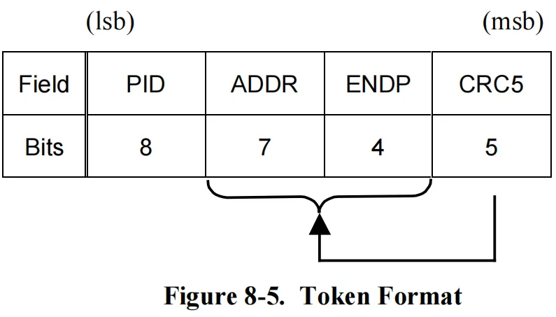
The token packet consists of the following fields:
- SYNC - Synchronization Field: used to help the receiver synchronize clocks and data
- PID - Packet Identifier: indicates that the current packet is a token packet, with a value of OUT, IN, SOF or SETUP
- ADDR - Device Address: Specifies the address of the target device for data transmission
- ENDP - Endpoint Number: Specifies the target endpoint number for data transmission
- CRC5 - 5-bit Cyclic Redundancy Check: used to verify the integrity of the preceding fields
- EOP - End of Packet Marker: Indicates the end of the current token packet
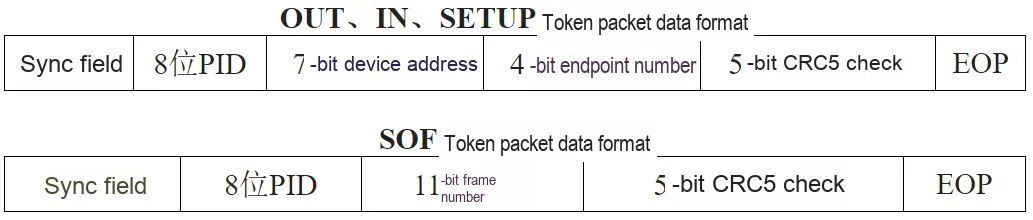
Among the four types of token packets listed in the above table, the OUT, IN and SETUP packets share the same data format, while the SOF token packet is slightly different. The CRC5 check for each token packet only verifies the data following the PID field:
- OUT token packet:
- The host notifies the device that it is about to send a data packet to it
- The device needs to be ready to receive data
- IN token packet:
- The host informs the device that it needs to read data from it
- The device needs to prepare to send data
- SETUP token packet:
- Similar to OUT, it notifies the device that a data packet is about to be sent.
- However, subsequent data packets can only be DATA0 and can only be sent to the control endpoint.
- SOF (Start of Frame) Token Packet:
- The host transmits periodically to synchronize with the devices.
2. Data Packet
The structure of the data packet is fixed as: after the sync field and PID, there are N bytes of data, followed finally by a 16-bit CRC16 checksum and the end-of-packet delimiter EOP.
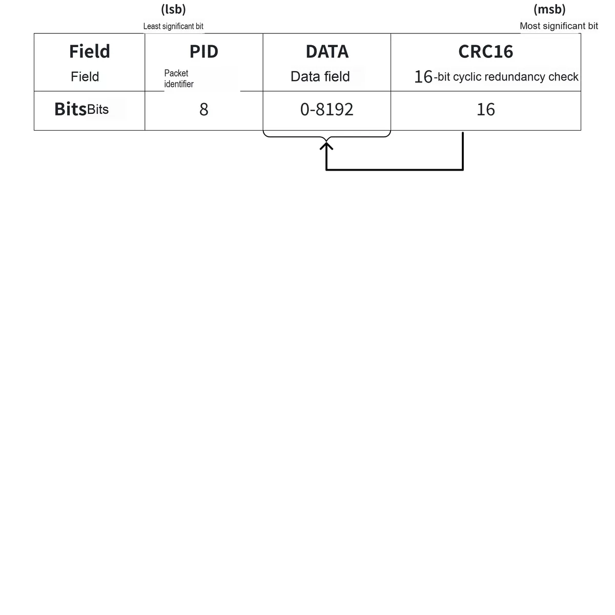
Wherein, the PID can be DATA0 or DATA1, which are two different types of data packets. This is a mechanism to ensure the reliability of data transmission in high-speed transmission mode, and the USB 1.1 protocol defines exactly these two types of data packets, DATA0 and DATA1:
- Alternate use of DATA0 and DATA1:
- Hosts and devices alternate between these two packet types when transmitting data.
- help the receiving end identify the sequence of data packets
- Fault-tolerant and error-correction mechanism:
- When the receiving end detects a mismatch in the data packet type, it will consider that an error occurred in the previous transmission.
- This will trigger the retransmission mechanism and improve the reliability of data transmission.
- Data Packet Type Switch:
- The host and the device each maintain a finite-state machine for packet type switching
- After successfully transmitting or receiving data, the system will switch to the next packet type
DATA2 and MDATA packets were additionally introduced in USB 2.0, which are applied in high-speed split transactions and high-speed, high-bandwidth synchronous transmissions:
- DATA2 Data Packet
- Used for High-Speed Split Transaction
- Used for split data transmission between a USB Host and a high-speed device
- improved the interoperability between hosts and high-speed devices
- MDATA data packet
- Used for High-Speed High-Bandwidth Isochronous transmission
- Multiple data packets can be transmitted within a single microframe.
- suitable for applications with strict requirements for real-time performance and bandwidth
3. Handshake Packet
The handshake packet consists of a synchronization field, a PID, and an EOP, which are used to acknowledge a transmission:
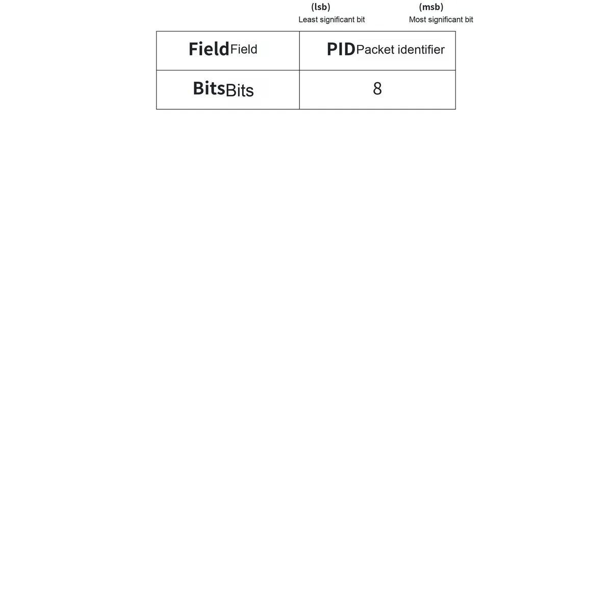
Common handshake packet types include the following:
- ACK: The host or device has successfully received the data
- NAK: The device notifies the host that the data is not yet ready
- STALL: The endpoint of the device is suspended
- NYET: Indicates that the device has successfully received the current data, but there is insufficient space to receive the next data.
4. Special Packet
Special packages are used for certain special functions, including:
- SOF (Start of Frame)
- Special packets periodically sent by the host
- Used for synchronization with devices
- Contains the frame number in milliseconds
- RESET
- The host sends to reset the USB device
- The device enters the default state upon receiving a RESET signal
- SPLIT
- used to implement split transactions between high-speed devices and full/low-speed devices
- The host first sends a SPLIT packet to full-/low-speed devices, and then performs data transmission.
- ERR
- Indicates that an error has occurred in a high-speed split transaction
- PING
- The host sends [a signal] to check whether the high-speed device is ready to receive data
- High-speed devices respond with ACK or NAK, which can be used for flow control of high-speed devices
1.1.9 USB Data Frames and Transactions
In USB data transmission, the top-level unit is a data frame, each of which lasts for 1 millisecond. A frame consists of a Start-of-Frame (SOF) data packet and one or more transactions, and the SOF marks the start of a new frame on the USB bus.
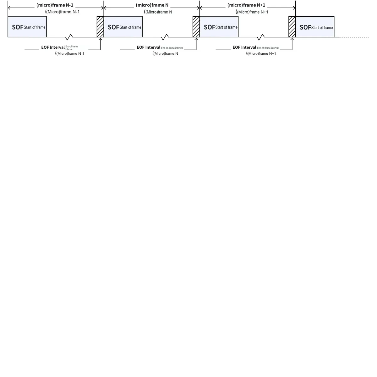
The basic transmission unit of USB is called a transaction, and a complete transaction consists of the following steps:
- Token Phase
- The host sends a Token Packet to specify the target device and endpoint of this transaction
- Token packets fall into three types: IN, OUT and SETUP, which are respectively used to indicate the direction and type of data transmission.
- Data Phase
- If there is data to be transmitted, the host or device will send a Data Packet.
- The size of the data packet is limited by the maximum packet length of the endpoint.
- Data transmission can be in the IN direction (from the device to the host) or the OUT direction (from the host to the device).
- Status Phase
- The receiver sends a Handshake Packet to indicate the status of data transmission (success/failure)
These three phases constitute a complete USB transaction. The host adopts different transaction types, such as control, bulk, interrupt and isochronous transmission, according to the endpoint type of the device. Based on the device descriptor information, the host reasonably schedules transactions among various devices to avoid conflicts and ensure fairness. This phased transaction mechanism enables the USB protocol to flexibly adapt to the requirements of different types of data transmission and provides an efficient and stable operating environment for devices.
Based on the above, the relationships among Frame, Transaction and Packet are as follows: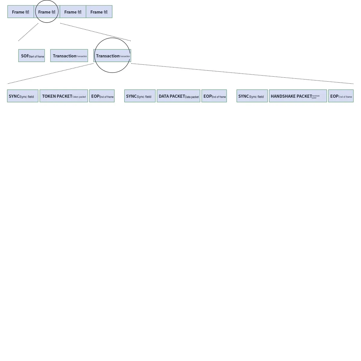
- Data frames provide the basic framework for time synchronization and scheduling.
- A transmission transaction is a basic data interaction unit completed within a single data frame.
- Each transaction consists of multiple data packets, which are the smallest transmission units.
1.2 Overview of USB Peripherals for Raspberry Pi Pico
The RP2040 chip of the Raspberry Pi Pico integrates a USB 2.0 controller, which can operate in either of the following modes:
- A full-speed device (12Mbps)
- A host capable of communicating with low-speed (1.5 Mbps) and full-speed devices, comprising multiple downstream devices connected to a USB hub
The RP2040 chip integrates a USB 1.1 PHY chip internally, and the USB controller is connected to the chip's DP (D+) and DM (D-) pin interfaces via the PHY chip. The hardware of the USB controller implements the functions of the USB physical layer, data link layer and part of the transaction layer, which means that programmers do not need to manually handle the complex details of the USB protocol, but instead focus on the following tasks:
- Configure controller parameters, such as device address, endpoints, etc.
- Provide a data buffer for the controller to transmit and receive data
- Respond to interrupt events of the controller, such as data transfer completion and endpoint status change
The USB controller features a 4kB DPSRAM, which is used to store the configuration information of the USB device and the data buffer.
USB controllers can operate in two working modes:
- Device Mode:
- USB 2.0 compatible full-speed device (12Mbps)
- It supports up to 32 endpoints (ranging from 0 to 15 for each of the input and output directions)
- This device supports control, isochronous, bulk and interrupt endpoint types, and supports double buffering.
- There are 3840 bytes of available buffer space in the DPSRAM, which is equivalent to a buffer of 60 × 64 bytes
- Host Mode:
- It can communicate with full-speed (12Mbps) devices and low-speed (1.5Mbps) devices.
- It can communicate with multiple devices via a USB hub, including low-speed devices connected to a full-speed hub.
- The device can poll up to 15 interrupt endpoints in hardware
- Interrupt endpoints are used by hubs to notify the host of connection/disconnection events, and by mice to notify the host of movements and the like.
The structure of the USB peripheral is as follows:
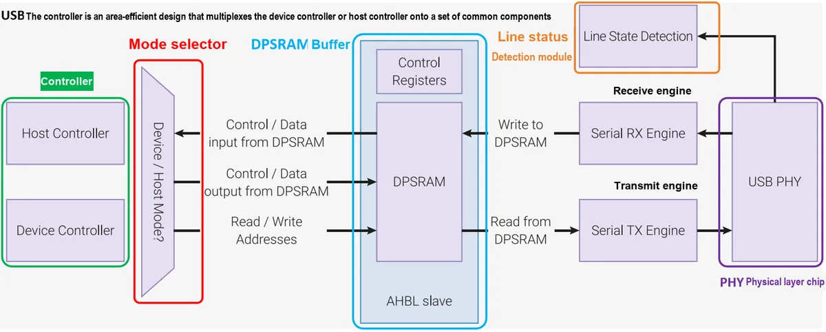
It can be seen that USB peripherals are mainly composed of the following parts:
- Integrated USB PHY chip
- Responsible for implementing the USB physical layer protocol, including electrical characteristics, signal coding, differential transmission, etc.
- provides the electrical interface between the USB DP and DM pins and the controller's digital logic
- The USB PHY driver transmits data via the DP and DM pins and performs differential reception of any incoming data.
- The USB PHY provides single-ended and differential received data to the line status detection module
- USB controller
- Responsible for implementing the protocol stack and endpoint management for the USB device side
- responsible for data reception and transmission, as well as the generation and decoding of control signals
- buffer memory
- DPSRAM is used to store control registers and data buffers.
- The USB controller features a 4kB (4096-byte) DPSRAM (Dual-Port SRAM).
- DPSRAM can be accessed as a 32-bit width memory at address 0 of the USB controller (0x50100000)
- DPSRAM supports 8/16/32-bit access, but does not support set/clear aliases.
- The data buffer is usually 64 bytes long:
- For the isochronous synchronous transmission mode, the maximum buffer size is 1023 bytes.
- For other transmission modes, the maximum size of each buffer is 64 bytes.
- The DPSRAM in the USB controller shall be regarded as asynchronous rather than atomic:
- It is a dual-port SRAM, which means that the processor has a port to read and write memory, and the USB controller also has a port to read and write memory. This allows the processor and the USB controller to access the same memory address simultaneously: one may be writing while the other is reading. If the processor writes to memory while the controller is reading from it, inconsistent data may be obtained, so care must be taken to avoid this situation.
- Line Status Detection Module
- Define and detect several line states (bus reset, connection, suspend, resume, data 1, data 0, etc.)
- The line status detection module has several finite-state machines to detect these statuses and notify other hardware components of event signals
- There is no shared clock signal in USB, so RX data must be sampled by an internal clock
- The maximum data rate of USB Full-Speed is 12 Mbps. RX data is sampled at a rate of 48 MHz, which provides 4 clock cycles for bus state capture and filtering, and the line status detection module distributes the filtered RX data to the serial RX engine.
- Receiving Engine
- The serial receive engine is responsible for decoding the received data captured by the line status detection module, and it generates the following information:
- PID (Packet Identifier) of inbound packets
- Device address address of inbound data
- Device endpoint for inbound data
- data byte
- The serial receive engine also detects errors in RX data by performing CRC check on inbound data. Any error will signal other hardware blocks and may trigger an interrupt.
- If the USB cable is disconnected during packet transmission in either host mode or device mode, the hardware will trigger an error.
- The serial receive engine is responsible for decoding the received data captured by the line status detection module, and it generates the following information:
- Sending Engine
- The serial transmit engine is the mirror of the serial receive engine. It connects to the currently active controller (whether it is a device or a host). It generates TOKEN and DATA packets, including calculating the CRC, and transmits them over the bus.
2. Software Control Method
For MicroPython, it divides USB devices into the following two types:
- "Runtime" USB Device:
- Defined after MicroPython startup using the Python API (
USBDeviceclass); - It needs to be configured and activated at runtime.
- Defined after MicroPython startup using the Python API (
- "Built-in" USB devices:
- Compile into the MicroPython firmware and it will always be available;
- It usually includes USB-CDC (serial port) and optional USB-MSC (mass storage);
- Out Of The Box, no additional configuration required.
MicroPython provides the USBDevice class, which is a low-level Python API for implementing USB device drivers:
- Constructor:
USBDeviceis a singleton class, and every call to its constructor returns the same object reference;
- Main Methods:
config ()method is used to configure the descriptors and callback functions of USB devices;active ()method is used to activate and deactivate runtime USB devices;builtin_driverattribute is used to get/set the built-in USB driver configuration;remote_wakeup ()method is used to wake up the USB host that is in the suspended state;submit_xfer ()method is used to submit non-control transfers;stall ()The method is used to set and get the STALL status of an endpoint;
- Constants:
BUILTIN_NONE,BUILTIN_DEFAULT,BUILTIN_CDC,BUILTIN_MSC,BUILTIN_CDC_MSCrepresent different built-in USB driver configurations
Unfortunately, according to the answer in the link below, we can see that for the Raspberry Pi Pico, it is not possible to use the USBDevice class to control "Runtime" USB devices as can be done with the PyBoard featuring STM32 chips:
https://github.com/micropython/micropython/issues/6811
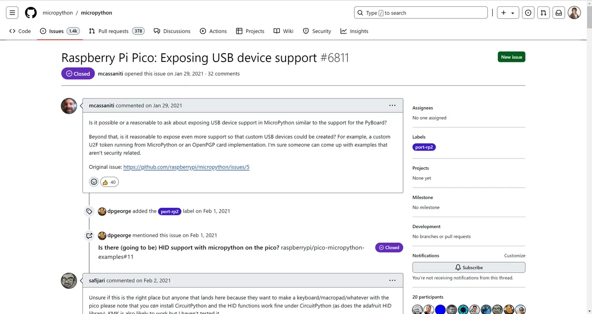
However, recalling what we introduced about the REPL interactive interpreter, on the Raspberry Pi Pico, the MicroPython firmware comes with a built-in USB-CDC device driver by default, which provides a virtual serial communication channel. This USB-CDC device is a "Built-in" device integrated into the MicroPython firmware and can be used without additional configuration. This means that we can use this virtual serial port together with the system's input and output to complete USB data transmission.
3. Application Examples
3.1 Use the USB-CDC class VCSP virtual serial port to complete data reading and writing
A virtual serial port refers to a USB device that is simulated as a traditional serial port device (COM port), enabling interaction with it using standard serial port Communication Protocol and software. Its main features include:
- It provides standard serial port interfaces and functions, such as the configuration of baud rate, data bits, stop bits and other parameters.
- It appears as a standard serial port device in the operating system and can be accessed by common serial port applications.
- Use
CDC(Communication Device Class) USB protocol to convert the data communication of USB devices into standard serial communication - It is usually used in scenarios where compatibility with legacy software or devices is required, such as industrial control systems, testing equipment, etc.
This design of virtual serial port greatly enhances the compatibility and usability of USB devices, allowing even legacy systems to seamlessly connect to new USB devices. The USB driver of the operating system automatically converts USB devices into standard serial port devices, which can be used by upper-layer applications without any modification.
The following code can be found in the elegance-devkit v1\Demo\39 USB_CDC folder of the resource package we provide.
The sample code is as follows:
# Python env   : MicroPython v1.23.0
# -*- coding: utf-8 -*-
# @Time    : 2024/7/29 1:22 PM
# @Author  : Li Qingshui
# @File    : main.py
# @Description : USB CDC experiment, using the USB-CDC class built into the MicroPython firmware on the Pico to perform read and write operations

# ======================================== Import Modules ========================================

import select
import sys
import time

# ======================================== Global Variables ============================================

# List recording the elapsed times
delta_list = [0] * 10
# Record the number of reads
read_count = 0

# ======================================== Functions ============================================

# ======================================== Custom Classes ============================================

# ======================================== Initialization ==========================================

# Delay to wait for the device to initialize
time.sleep(3)
# Print debug information
print('FreakStudio : Using USB CDC to read and write data')

# Create a select.poll() object to listen for incoming standard input data
poll_obj = select.poll()
# Register the standard input sys.stdin with the poll_obj object, specifying select.POLLIN as the event type (listen for input events)
poll_obj.register(sys.stdin, select.POLLIN)

# ========================================  Main Program  ===========================================

# Enter an infinite loop; the select module is used below to perform non-blocking reads and writes
while True:

    # After 10 data reads
    if read_count == 10:
        # Set read_count to 0
        read_count = 0
        # Output the average time taken to send data over the 10 reads
        avg_delta = sum(delta_list) / len(delta_list)
        print("avg time cost : " + str(avg_delta) + " ms\r")

    # Use the poll_obj.poll(1) method to wait for incoming standard input data, with a timeout of 1 ms
    poll_results = poll_obj.poll(1)
    if poll_results:

        # If data has arrived (i.e. poll_results is not empty), read the data from standard input and write it to standard output
        # readline() reads one line of data from standard input (ending with a newline character) and returns a string containing that line
        # The strip() method removes whitespace characters from both ends of the string, including spaces, tabs, newlines, etc.
        # data = sys.stdin.readline().strip()
        # sys.stdin.readline().strip() is a non-blocking read
        # input() is a blocking read and will block program execution
        data = input("please input data : ")

        # Test the time taken to write out the data
        t = time.ticks_us()

        # Write the data to standard output
        # The sys.stdout.write() method can also be used
        # sys.stdout.write("received data : " + data + "\r")
        # sys.stdout.write() writes data directly to the standard output stream without buffering
        # print() first stores the output in a buffer, and only actually outputs it when the buffer is full or a newline character is encountered
        print("received data : " + data + "\r")

        # Calculate the time taken for one read/write
        delta = time.ticks_diff(time.ticks_us(), t)/1000
        # Output the time taken by this read/write
        print("time cost : " + str(delta) + " ms\r")

        # Add the time taken by this read/write to the delta_list list
        delta_list[read_count] = delta
        # Increment the read count by 1
        read_count += 1

    else:
        # If no data has arrived (i.e. poll_results is empty), continue the loop
        continue
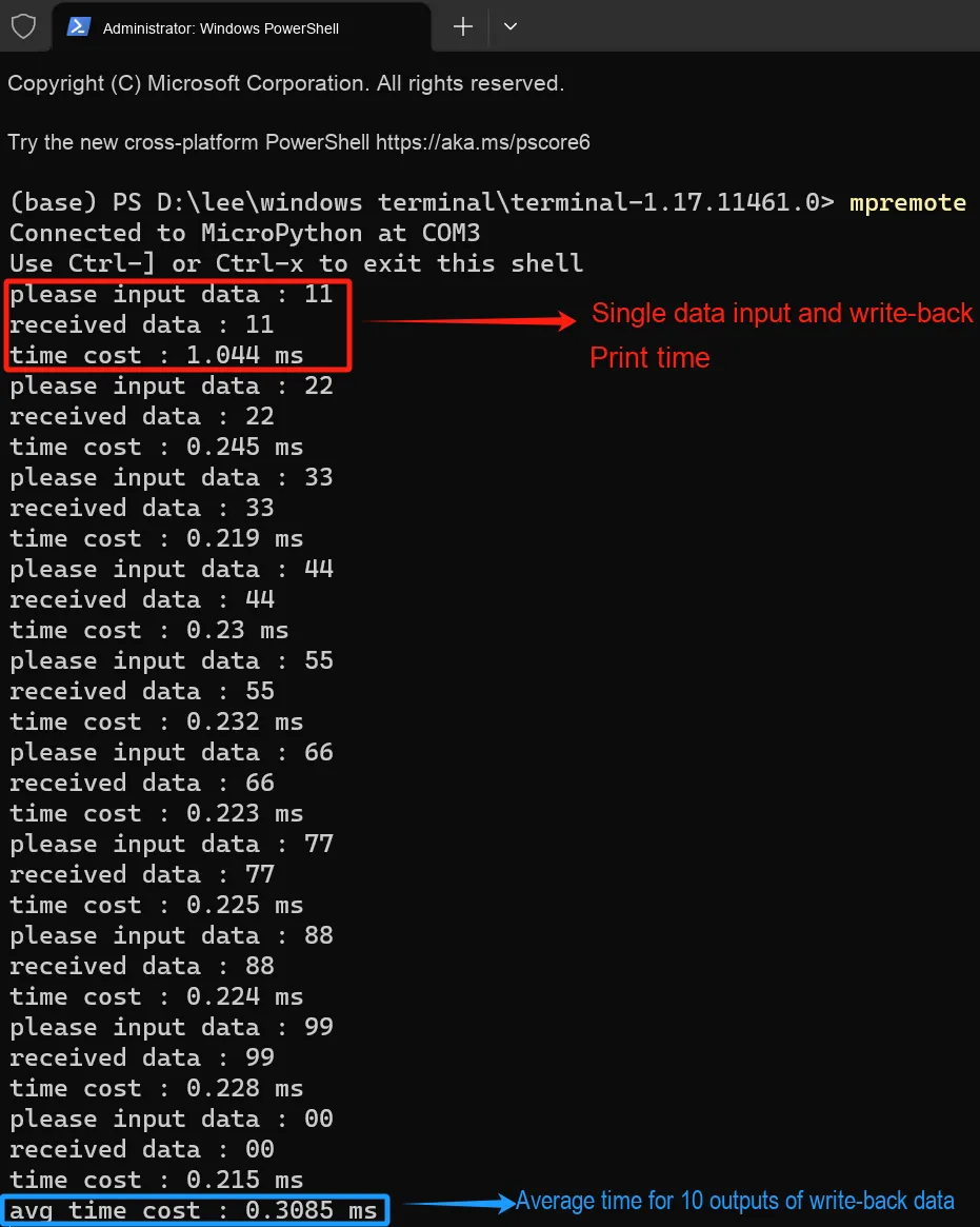
Here, we use the select module to monitor standard input; when data arrives, we utilize the print function and input function to complete reading and writing back, meanwhile measure the read-write time consumption and calculate the average value, so as to simulate the data interaction scenario between the USB device and the host.
Burn the code, open the remote terminal, and input data; you can see that the input data is written back to the terminal:
3.1 Application Experiment.mp4 22.8 MB
Here, for the convenience of demonstration, we use the blocking input method for reading. In actual data transmission, we expect to read the standard input in a non-blocking manner so as to continuously monitor whether there is data input, and usually the sys.stdin.readline (). strip () method is used for reading. The differences between the two are as follows:
sys.stdin.readline (). strip ()is a non-blocking read operation that will not block the program when there is no data inputinput ()is a blocking read operation, which will block the execution of the program when there is no data input.
When outputting the received data, we use the familiar print function, but in practical applications, we will adopt the sys.stdout.write () method to ensure real-time performance. The differences between the two are as follows:
print ()function is a standard built-in output function in Python. It outputs the specified content to the screen and automatically appends a newline character. The print () function first stores the output content in a buffer, and the content will not be actually output until the buffer is full or a newline character is encountered.The sys.stdout.write ()method is a function in the Python standard library that writes a string to the standard output stream without automatically appending a newline character. If you want to output content immediately without waiting for the buffer to fill up, you can use the sys.stdout.write () method.
References
- Read/write data over Raspberry Pi Pico USB cable
https://stackoverflow.com/questions/76138267/read-write-data-over-raspberry-pi-pico-usb-cable
- USB, which has been transforming the world for over two decades, did you know that the person who invented it has never earned a single penny from it?
https://today.line.me/tw/v2/article/nJXr7M
- Introduction to USB Protocol
https://gaoyichao.com/Xiaotu
- Getting Started with STM32
https://gaoyichao.com/Xiaotu/?book=stm32&title=index
- Universal Serial Bus Specification Revision 2.0
- USB interface
https://toshiba.semicon-storage.com/ap-en/semiconductor/knowledge/e-learning/village/usb-interface-1.html
- How USB Works: Introduction (Part 1)
https://www.circuitbread.com/tutorials/how-usb-works-introduction-part-1
- USB Wikipedia
https://en.wikipedia.org/wiki/USB
- Learning USB from Scratch: An In-Depth Analysis of the Organization Form of USB Data Transmission
https://developer.baidu.com/article/details/3197558
- class USBDevice – USB Device driver
https://docs.micropython.org/en/latest/library/machine.USBDevice.html
Version Record
Version Number | Modifier | Time | Content |
v1.0.0 | Li Zisheng | 2025/09/16 | Initialize the document, based on MicroPython version V1.23.0. Only the USB-CDC class has been tested, and the rest have not been tested. |
v1.1.0 | Li Zisheng | 2025/12/15 | All the images have been modified completely. |