
Contents
- 1. Hardware Explanation
- 1.1 1-Wire Communication Protocol
- 1.2 Explanation of 1-Wire Communication Protocol
- 1.3 Overview of the Single-Wire Interface for Raspberry Pi Pico
- 2. Software Control Method
- 3. Application Examples
- 3.1 Temperature and Humidity Reading of DHT11 Sensor
- 3.2 MY18E20 Temperature Reading
- References
- Version Record
1. Hardware Explanation
1.1 1-Wire Communication Protocol
1.1.1 Introduction to 1-Wire Communication Protocol
1-Wire is a wired half-duplex serial bus designed by Dallas Semiconductor that provides low-speed (typical communication rate is 16.3 kbit/s, maximum communication rate can reach 142 kbit/s) data communication over a single conductor, it uses a single signal line to transmit clock and bidirectional data.
1-Wire bus communication is commonly used in communication scenarios with a single master and multiple slave devices, such as the communication between a microcontroller unit and small sensor devices (e. g., digital thermometers and meteorological instruments).
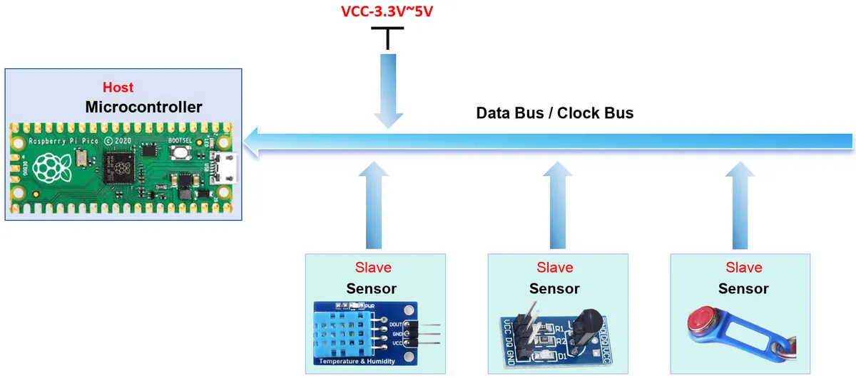
1-Wire bus communication has two notable features:
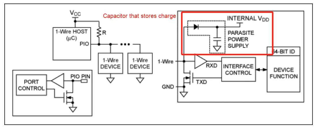
- Power can be supplied via the data line. The sensor using 1-Wire communication has a small integrated capacitor (~800 pF) inside to store charge, and this capacitor powers the device while the data line is active:
- 1-Wire communication is designed for transient contact scenarios; if the host disconnects from the 1-Wire bus or loses contact with it, all 1-Wire slave devices connected to the bus will enter a reset state (for example, due to power loss), and when the voltage is restored, the slave devices will wake up and send out a signal.
In addition, 1-Wire bus communication boasts the advantages of simple wiring, low hardware overhead, low cost, and ease of bus expansion and maintenance.
1.1.2 Development History and Application of 1-Wire Communication Protocol
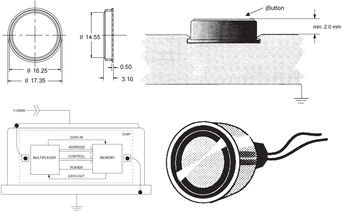
The 1-Wire Communication Protocol was invented by Dallas Semiconductor in the 1980s. The main purpose of its invention was to use chips to produce machine-readable tags as a replacement for human-readable tags, and apply such tags to scenarios including large supermarkets, warehousing and logistics. The earliest device that adopted the 1-Wire Communication Protocol was the iButton touch socket, and we can refer to the iButton standard via the following link:
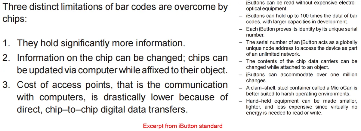
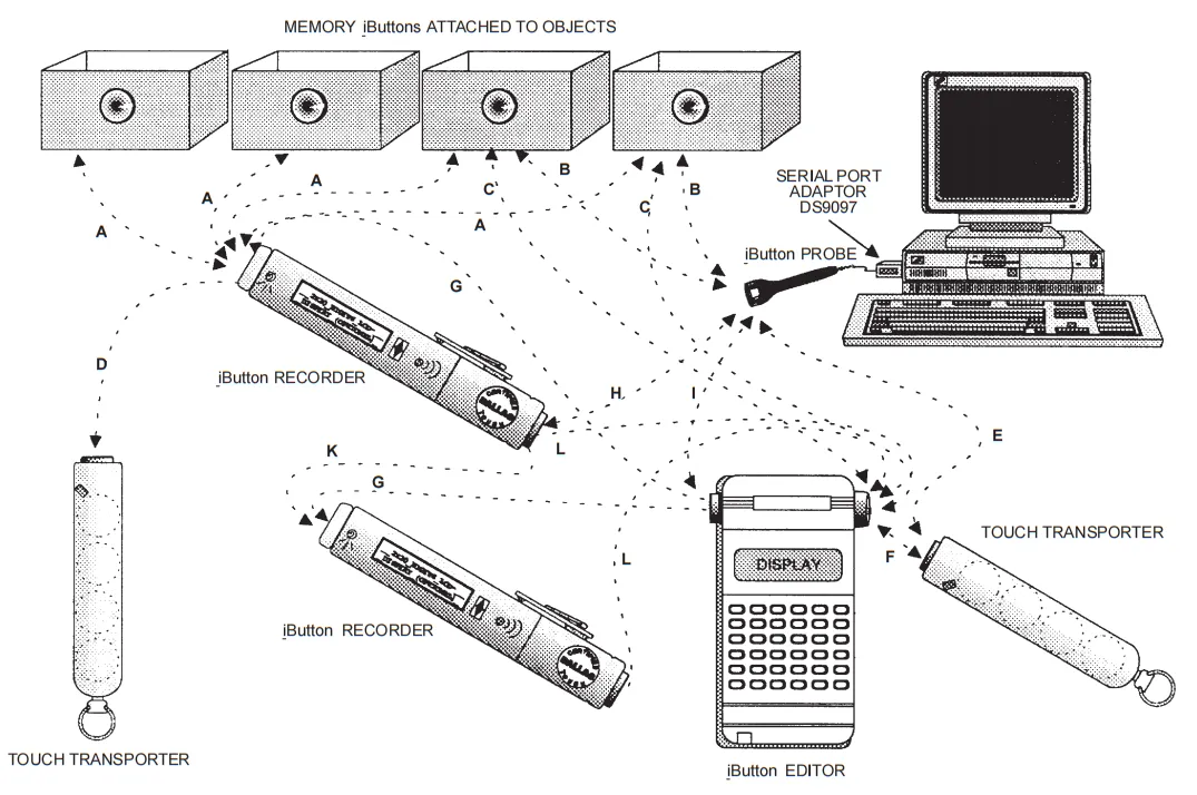
Simply put, the iButton standard is similar to the current 1-Wire single-bus protocol;the iButton standard in its simplest configuration consists of one data line and one ground line, with only some specific requirements in terms of circuit structure:
- The ground wire consists of a two-piece stainless steel container
MicroCan™, which also serves as a protective enclosure; - The data cable is a cup-shaped probe with a circular surface.
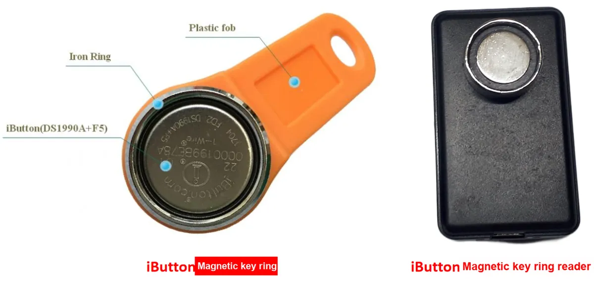
The most common 1-Wire communication device is the iButton magnetic key fob (also known as the Dallas key), which consists of a button cell, an outer iron ring, a plastic keychain, and an internal circuit board. The iButton magnetic key fob needs to be used with a card reader, and the two identify any iButton as a specific 48-bit ID number via the 1-Wire Communication Protocol. iButtons can be embedded in rings, tags, and other personal items that can be carried around to identify specific people or objects.
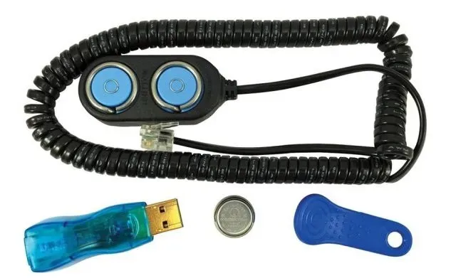
The following is a physical image of the iButton touch socket device that was popular in the 1980s for unlocking personal computers:
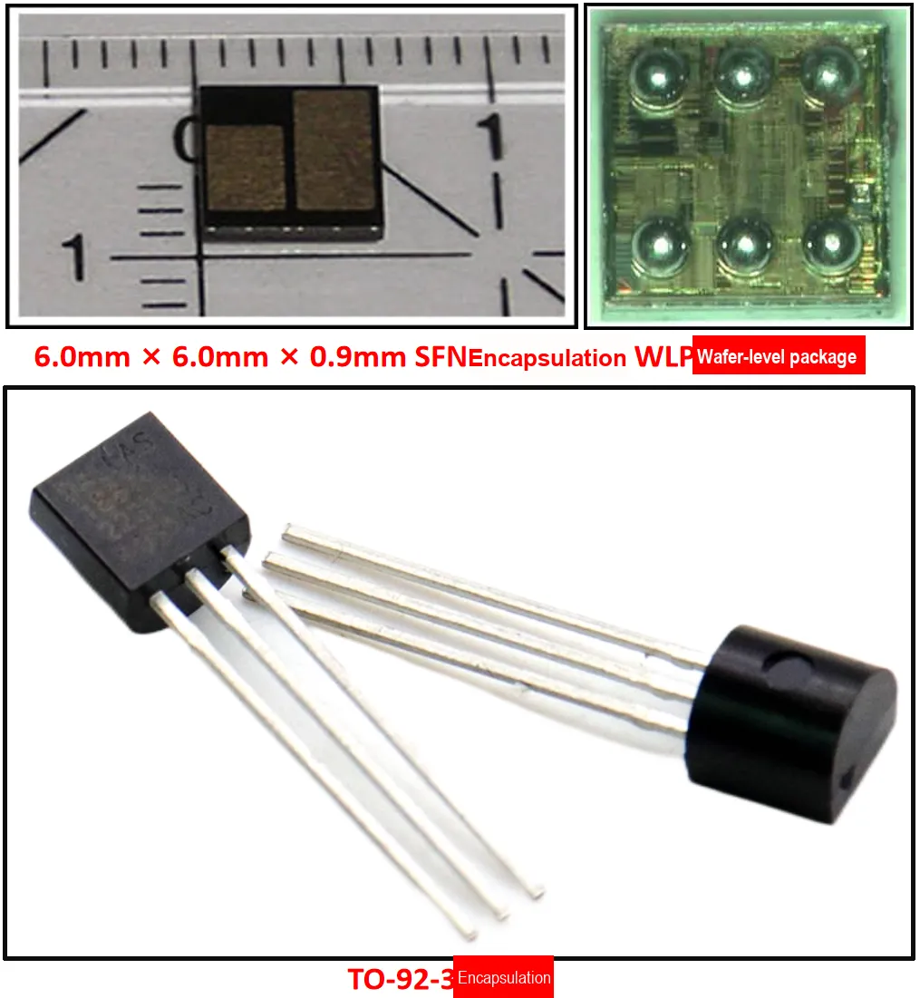
Apart from the standard iButton circuit interface, 1-Wire communication devices also come in packages of conventional transistors (TO-92) and ICs (TSOC, TDFN, SOT23):
Currently, the level standards adopted by 1-Wire devices can be divided into the following four categories:
- 1.71V (minimum) to 1.89V (maximum)
- 1.71V (minimum) to 3.63V (maximum)
- 2.97 V (minimum) to 3.63 V (maximum)
- 2.8 V (minimum) to 5.25 V (maximum)
1-Wire devices can be classified into the following categories according to their functions:
Type | Example |
ID only | For example, DS2401, DS2411, DS1990A, DS1990R, etc. , which are used for printed circuit board (PCB) identification and printer cartridge identification |
Identification ID plus control | For example, DS2413 and DS2450, which are used for rack card control, accessory identification and control |
Identification ID plus Temperature | For example, the DS1920 used for temperature Data Acquisition |
Identification ID plus timestamp | For example, the DS2417 and DS1904 which use a 32-bit binary counter to measure time |
Identification ID plus NV SRAM | such as DS1992, DS1993, DS1995, etc. |
Identification ID plus One-Time Programmable (OTP) EPROM | For example, the DS2502-E48 and DS2502-E65 used for network addressing |
Identification ID plus EEPROM | For example, the DS28E05 used for medical consumables and PCB identification |
Identification ID plus SHA-256 ID verification and secure EEPROM | such as the DS28E22 and DS28EL22, which are used for key generation and exchange in identity authentication and password systems for network connection devices |
Identification ID plus SHA-256/ECDSA Authentication and Secure Memory | For example, the DS28E36, which is used for peripheral security authentication, IoT node protection, and firmware download |
Identification ID plus SHA-3 ID verification, ChipDNA™ Encrypted EEPROM | For example, the DS28E50 used for medical sensor and tool certification |
Identification ID plus data record | For example, DS1921G and DS1922L, which are used for temperature monitoring in environmental science and food safety |
Besides the above-mentioned 1-Wire devices used for device ID identification, many sensors in PCs also adopt the 1-Wire Communication Protocol, such as temperature loggers, timers, voltage and current sensors, battery monitors and memories, etc. These devices are connected to PCs via bus converters.
1.2 Explanation of 1-Wire Communication Protocol
1.2.1 Physical Layer
1.2.1.1 Connection Mode of 1-Wire Bus Communication
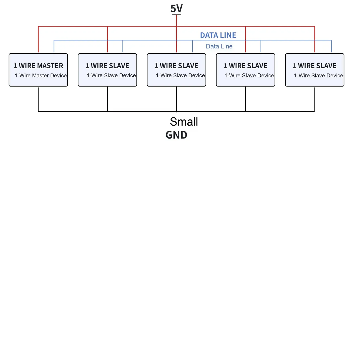
The 1-Wire bus uses only a single wire for both signal transmission and power supply. Its communication is asynchronous and half-duplex, and follows a strict master/slave scheme. One or more slave devices can be connected to the bus simultaneously, while only one master device is allowed to be connected to the bus.
1.2.1.2 Level Standards and Open-Drain Output
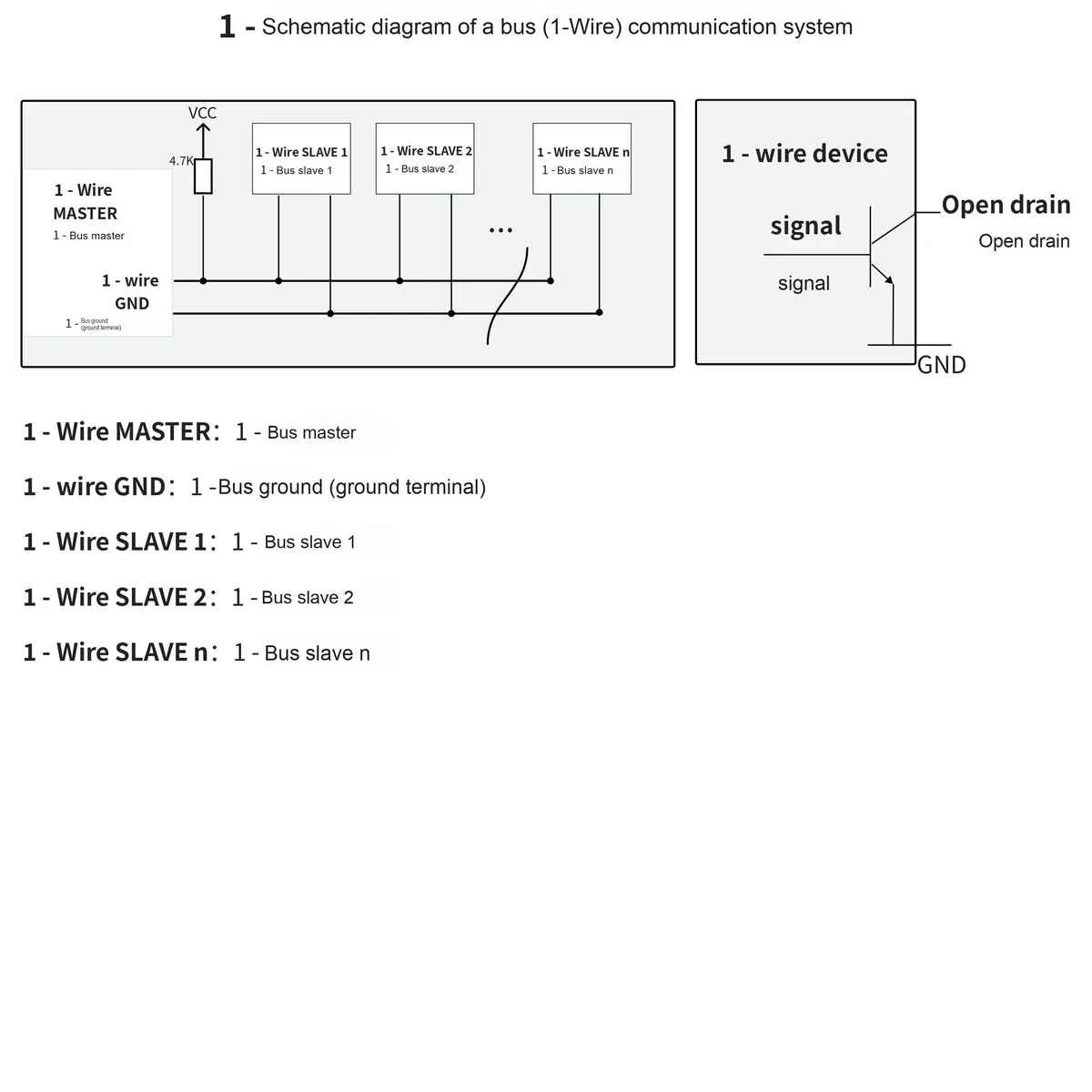
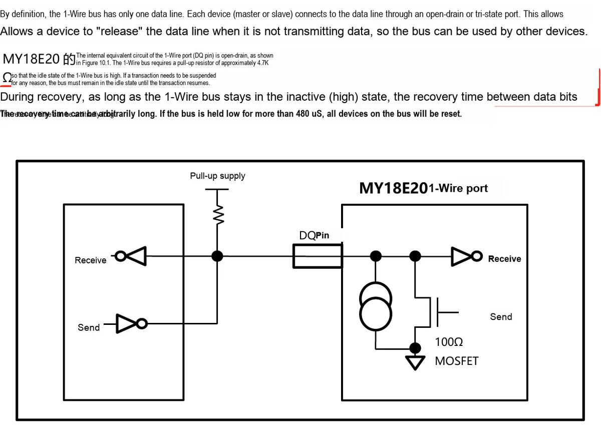
The 1-Wire protocol adopts CMOS/TTL levels, with the maximum value of low level being 0.8V and the minimum value of high level being 2.2V, and performs communication within the power supply voltage range of 2.8V to 6V. A 1-Wire master or slave device is connected to the data line via an open-drain or tri-state port; the bus is at a high level when idle, which is generated by a pull-up resistor typically of 4.7kΩ.
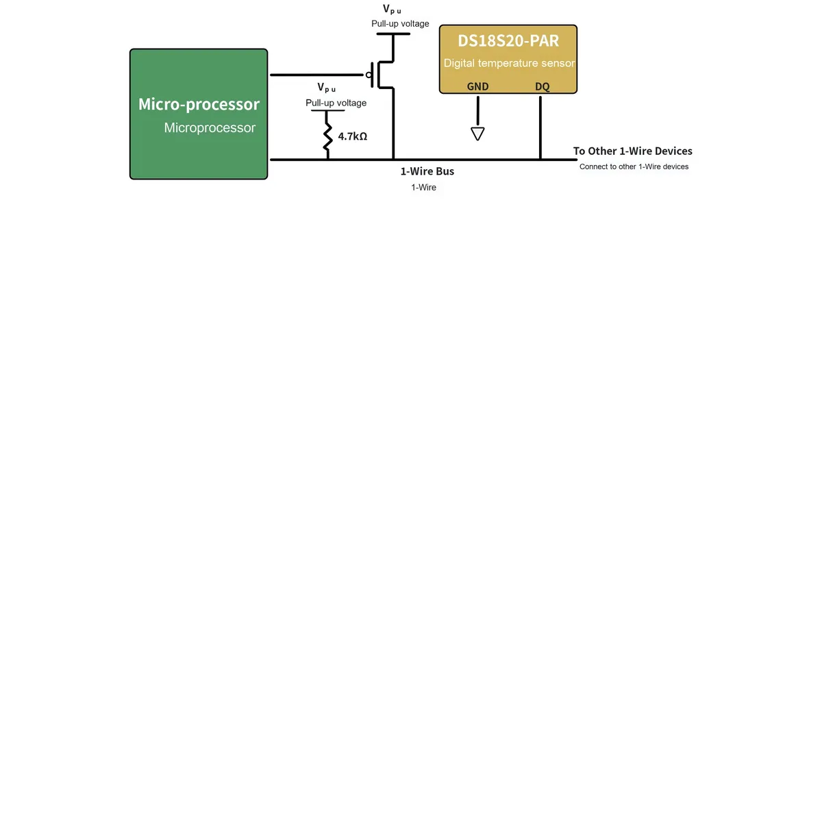
To ensure that certain devices on the bus have sufficient current supply during operation (for example, when the DS18S20-PAR temperature sensor performs temperature conversion or the E2PROM writes data), in addition to the pull-up resistor, it is also necessary to use a MOSFET on the bus to provide a strong pull-up power supply, and this strong pull-up is not required in most applications.
1.2.1.3 Power Supply for 1-Wire Devices
1. Independent power supply
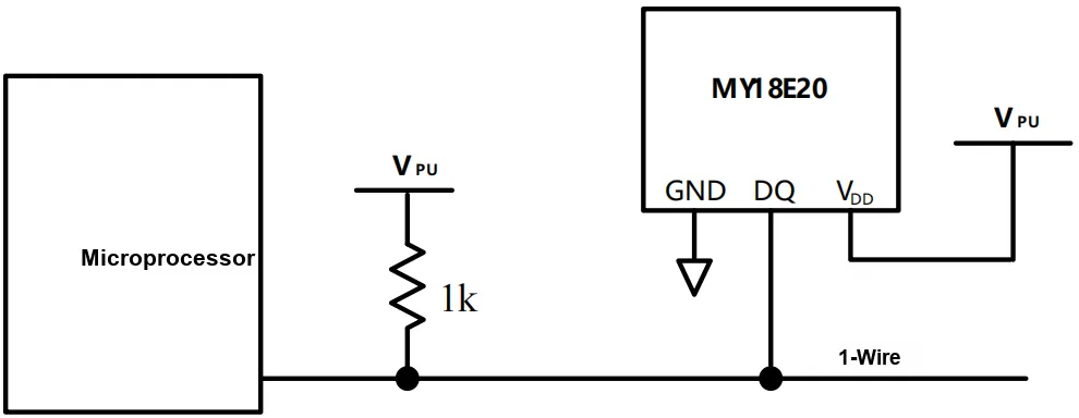
Taking the MY18E20 sensor as an example (a domestic alternative to the DS18B20 sensor), we can supply power via an external power source through the VDD pin. The advantage of this mode is that no MOSFET pull-up is required, and the 1-Wire bus can be used for any other operations during temperature conversion.
2. Parasitic Power Supply
Taking the DS18B20 sensor as an example, we can use the MOSFET pull-up connection method to power the 1-Wire bus devices:
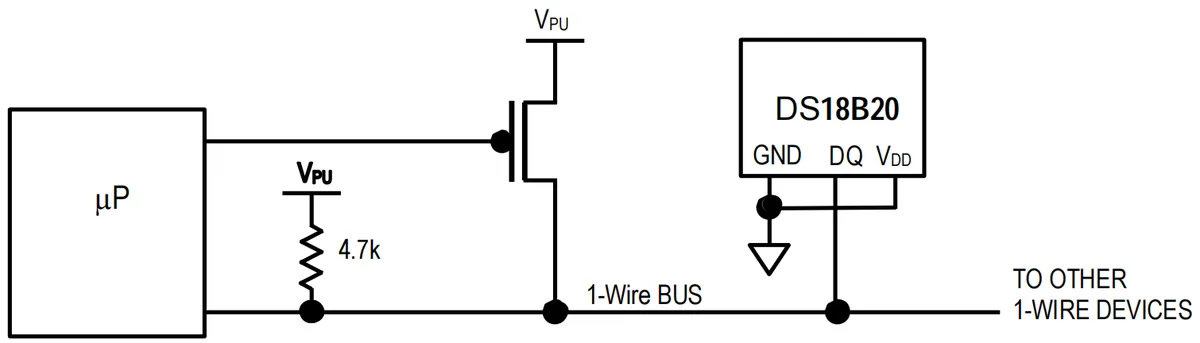
Parasitic power supply is mainly implemented by utilizing the unidirectional conductivity of diodes:
- When the single bus is at a high level: Vpu supplies power to the chip and charges the capacitor Cpp through the diode and pull-up resistor
- When the single bus is at a low level: the diode is reverse-biased, and the capacitor Cpp supplies power to the chip
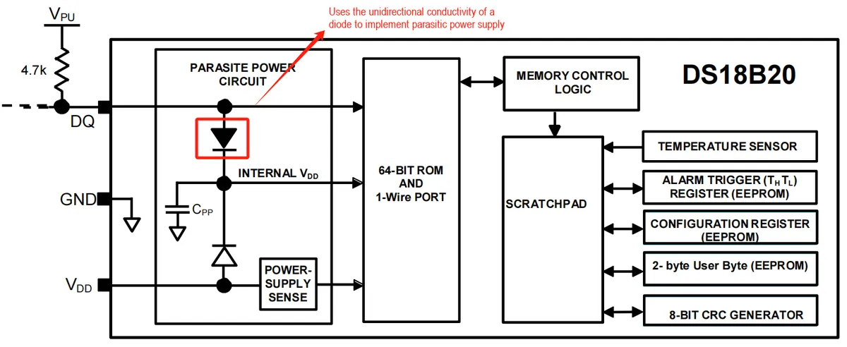
Here, the use of parasitic power supply requires the 1-Wire bus to intermittently provide a high level: on the one hand, this charges the capacitor Cpp; on the other hand, if the bus remains at a low level for more than 480 microseconds, the 1-Wire device will generate a reset signal.
1.2.2 Protocol Layer
1.2.2.1 1-Wire Communication Process
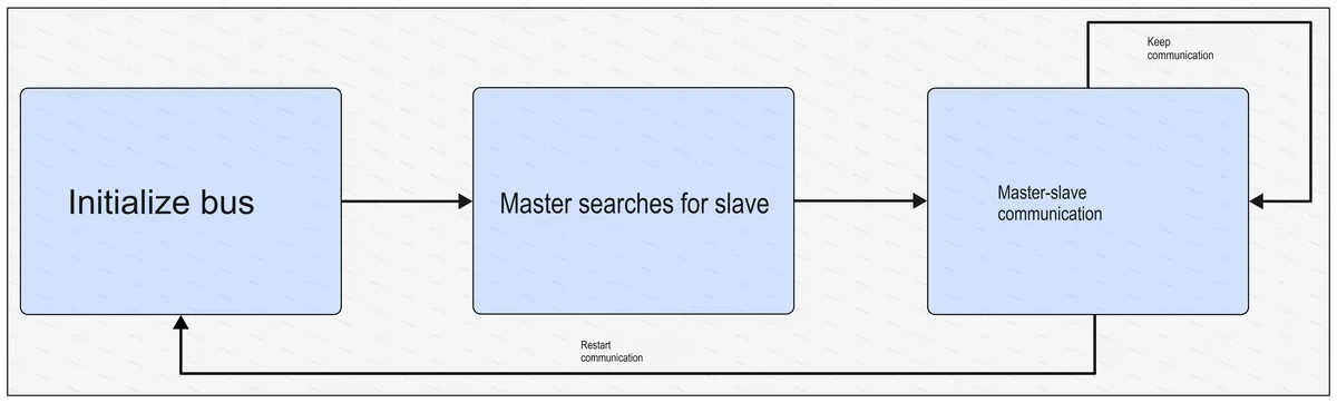
In 1-Wire bus communication, the communication between the master and the slave can be completed through three steps:
- Initialize the 1-Wire bus: The master sends a reset signal to reset the bus and synchronize the entire bus
- Master Searching for Slave Devices: The master sends a ROM command to call slave devices; after a slave responds, the master selects the specific target slave, while all other devices will exit the process and ignore any subsequent data sent by the master, and will not resume waiting for a call until the master issues the next reset signal.
- Communication between master and slave devices: The master device can send function commands or read/write data to the slave devices.
1.2.2.2 1-Wire Bus Communication Signal
The 1-Wire protocol specifies the following types of communication signals:
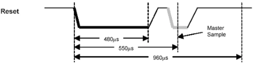
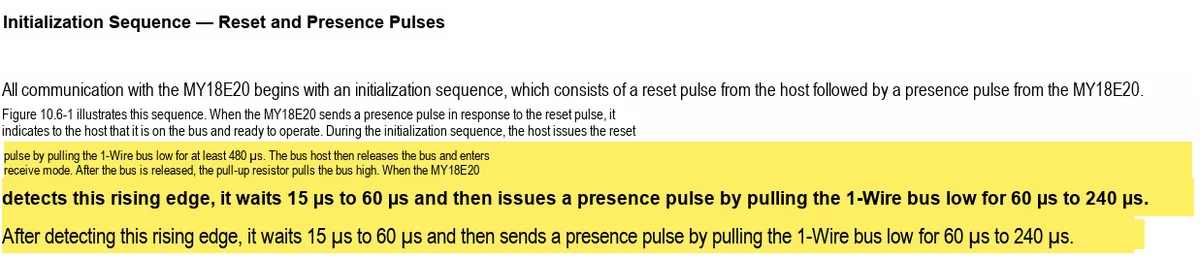
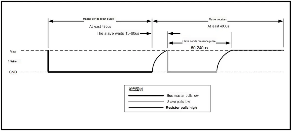
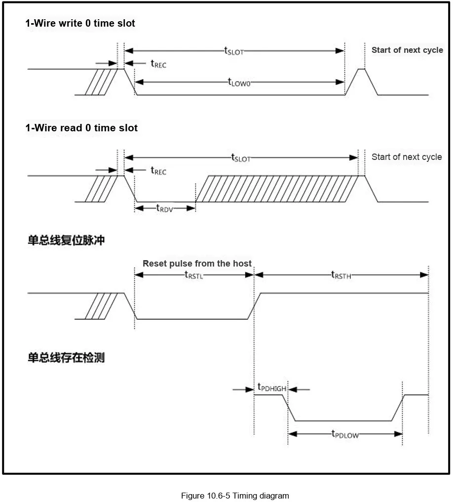
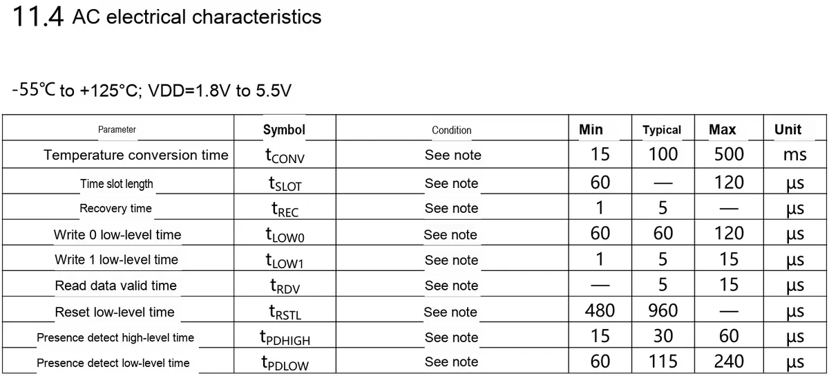
- Master Reset Signal and Slave Response Signal: The master generates a reset signal by pulling the single bus low for 480 to 960 microseconds, then releases the bus and enters the receive mode. When the master releases the bus, a rising edge (transition from low level to high level) is generated. After detecting this rising edge, the single-bus slave delays for 15 to 60 microseconds, then pulls the bus low for 60 to 240 microseconds to generate a response signal. When the master receives the response signal from the slave, it indicates that the single-bus device is ready and the initialization process is completed.
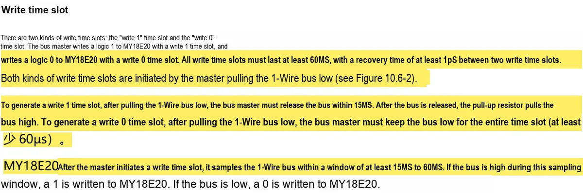
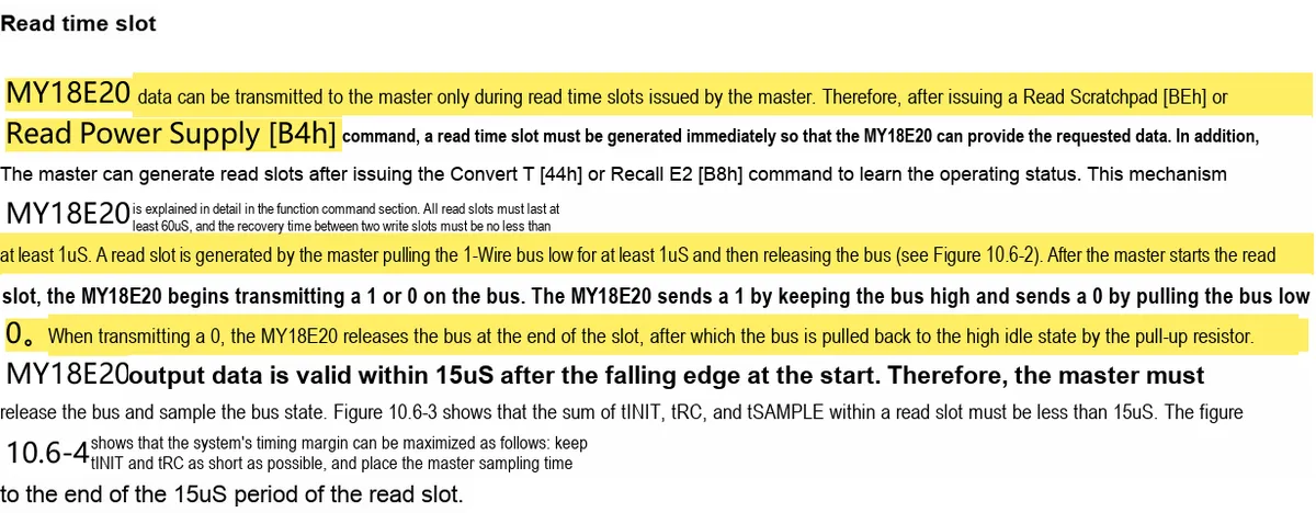
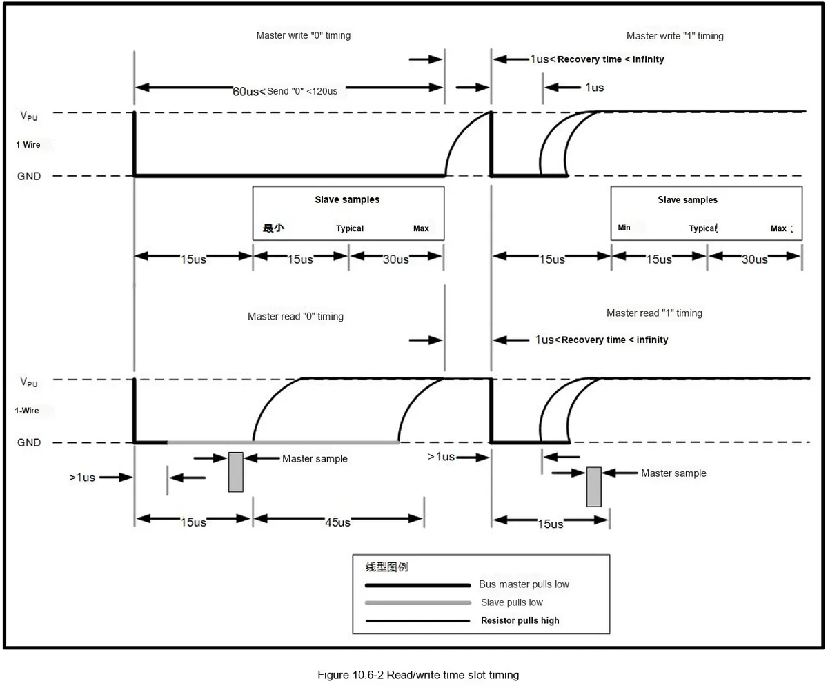
- Write Data 0 Signal: After the data line is pulled low, sample the data line within the time window of 15 to 60 microseconds. If the data line is at a low level, it indicates writing a 0; if the data line is at a high level, it indicates writing a 1. For the host to generate a Write Data 0 Signal, it must pull the data line low and hold it for 60 microseconds.

- Write Data 1 Signal: After the data line is pulled low, sample the data line within the time window of 15 ~ 60 us. If the data line is at low level, it means writing 0; if the data line is at high level, it means writing 1. For the host to generate a Write Data 1 Signal, it needs to pull the data line low, and then pull the data line high within 15 us after the Write Data 1 Signal starts.

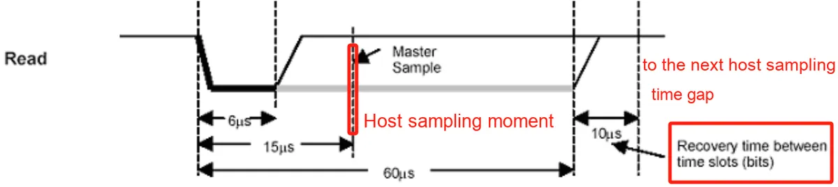
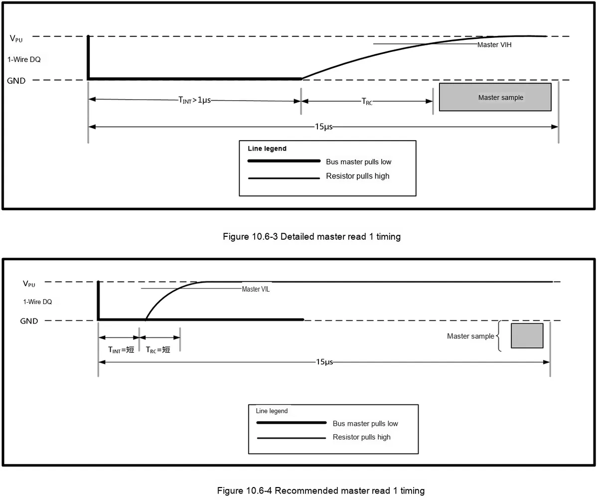
- Data reading signal: When the host pulls down the data bus, it must hold the bus low for at least 1µs before releasing it. Data must be read within 15µs, and the bus must be pulled high for at least 1µs before the next host read signal.
1.2.2.3 ROM Commands
It should be noted here that when the host accesses a 1-wire device, it must strictly follow the 1-wire command sequence, namely initialization, ROM command, and function command. If the sequence is disordered, the 1-wire device will not respond to the host (except for the Search ROM command and the Alarm Search command). The 1-wire protocol specifies the ROM commands, while the function commands are determined according to the functions supported by the specific 1-wire device.
Common ROM commands are listed as follows:
ROM command | Description |
Search ROM (F0h) | Identify the ROM codes of all 1-wire devices on the 1-Wire bus |
Read ROM (33h) (single-node only) | Directly read the serial number of the 1-wire device |
Match ROM (55h) | Find 1-wire devices that match the specified serial number |
Jump ROM (CCh) (single-node only) | This command can be used to directly access the slave devices on the bus. |
Alarm Search ROM (Ech) (Supported only by a small number of devices) | Search for slave devices with alarms |
1.2.2.4 Addressing Modes
Each 1-Wire slave device stores a unique 64-bit serial number in its ROM, which serves as its node address. The master device identifies the slave devices connected to the bus network via the ROM ID. The ROM ID is non-modifiable and is programmed inside the 1-Wire device via laser marking.
The ROM ID consists of eight bytes and is divided into three main parts: starting from the LSB, the first byte stores an 8-bit family code that identifies the device type.
The next 6 bytes store a customizable 48-bit individual address, and the last byte is a CRC check code calculated from the first 56 bits of the ROM code.

1.3 Overview of the Single-Wire Interface for Raspberry Pi Pico
There are two ways to implement single-bus communication using the Raspberry Pi Pico:
Implementation Method | Features |
Simulate via GPIO port | Use the delay function containing basic loops to implement bit read-write timing control, thereby realizing bus read and write It has the following characteristics:
|
Use UART in conjunction with external circuits | Connect both the TXD and RXD pins to the bus, and an external open-collector or open-drain buffer is required to allow the slave device to pull the bus low when the UART output is at a high level. 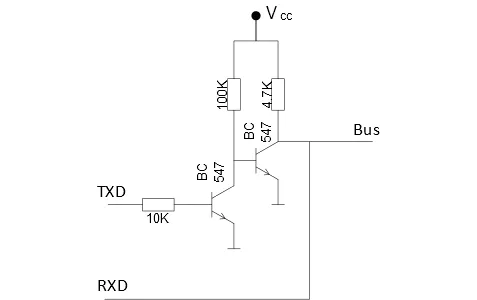 By configuring parameters such as the baud rate, valid data bits, and parity bit of the UART, the MCU only needs to place a single-byte character into the UART transmitter to complete 1-Wire bus data transmission; conversely, the single-byte character code read by the MCU corresponds to 1 bit of data transmitted by the 1-Wire slave device. When the UART data format in use is 8 data bits, no parity and 1 stop bit, one-wire communication can be implemented in the following manner: 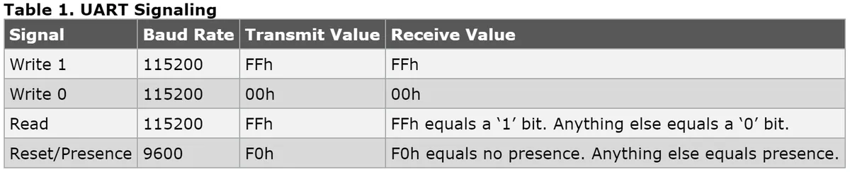 It has the following characteristics:
|
Here, we use the GPIO port to simulate the 1-Wire Communication Protocol via software, so that everyone can better understand the overall process of 1-Wire communication.
2. Software Control Method
Here, we implement one-wire communication by means of GPIO software simulation of the one-wire Communication Protocol, and the implementation refers to the following code:
https://github.com/robert-hh/Onewire_DS18X20/blob/master/onewire.py
First, let's define the 1-Wire communication class, whose main functions are as follows:
- Initialize one-wire communication: including configuring the pin to open-drain pull-up mode, and defining the methods for disabling and enabling interrupts.
- Implement the single-bus reset operation: which includes the host sending a reset pulse and determining whether the slave has a response.
- Implement read and write operations for single bits and single bytes: Meet the timing requirements by controlling the bus state and delay.
- Implement multi-byte read and write operations: which are completed by calling the single-byte read and write methods in a loop.
- Implement the function of selecting a device with a specified ROM ID: It is used to select a specific slave device.
- Implement a CRC8 check algorithm based on the table lookup method: which is used to verify whether the data read from the device is complete and correct.
- Implement the scanning function: a function that scans all devices on the bus and returns all matching ROM IDs.
First, we define several common command code constants for 1-Wire communication, such as the search command, the read ROM ID command, and so on:
# Define the one-wire communication class
class OneWire:
    """
    OneWire class, used to communicate through the one-wire protocol (OneWire), supporting interaction with OneWire devices (such as the DS18B20 temperature sensor).
    This class encapsulates the basic operations of OneWire communication, such as resetting the bus and sending and receiving data, and also provides a device search function.

    Attributes:
        pin (Pin): GPIO pin instance used for OneWire communication.
        crctab1 (bytes): The first byte table required by the CRC lookup table method.
        crctab2 (bytes): The second byte table required by the CRC lookup table method.
        disable_irq (function): Function to disable interrupts.
        enable_irq (function): Function to enable interrupts.

    Methods:
        reset(required: bool = False) -> bool: Reset the one-wire bus.
        readbit() -> int: Read one data bit from the one-wire bus.
        readbyte() -> int: Read one byte from the one-wire bus.
        readbytes(count: int) -> bytearray: Read multiple bytes from the one-wire bus.
        readinto(buf: bytearray) -> None: Read multiple bytes from the one-wire bus into a buf array.
        writebit(value: int, powerpin: machine.Pin = None) -> None: Write one data bit to the one-wire bus.
        writebyte(value: int, powerpin: machine.Pin = None) -> None: Write one byte to the one-wire bus.
        write(buf: bytearray) -> None: Write the data in the buf array to the one-wire bus.
        select_rom(rom: bytearray) -> None: Send the match ROM ID command.
        crc8(data: bytearray) -> int: CRC check, implemented with the lookup table method.
        scan() -> list[bytearray]: Scan all devices on the one-wire bus and return all matching ROM IDs.
        _search_rom(l_rom: bytearray, diff: int) -> tuple[bytearray, int]: Search the one-wire bus for the device with the corresponding ROM ID.
    """
    # ROM commands for one-wire communication
    CMD_SEARCHROM   = const(0xf0)  # Search command
    CMD_READROM     = const(0x33)  # Read ROM ID command
    CMD_MATCHROM    = const(0x55)  # Match ROM ID command
    CMD_SKIPROM     = const(0xcc)  # Address all devices simultaneously command
    # High level value
    PULLUP_ON       = 1
In the initialization method, we define the configuration pins as open-drain pull-up mode, define the methods for disabling and enabling interrupts, and two byte tables for CRC check:
def __init__(self, pin: machine.Pin) -> None:
    """
    Initialize the one-wire class, passing in the data pin object to use.

    Args:
        pin (machine.Pin): Data pin object.

    Returns:
        None
    """
    self.pin = pin
    # Initialize the pin in pull-up, open-drain mode
    self.pin.init(pin.OPEN_DRAIN, pin.PULL_UP)
    # Define the methods to disable and enable interrupts
    self.disable_irq = machine.disable_irq
    self.enable_irq = machine.enable_irq
    # Two bytes tables required by the CRC lookup table method
    self.crctab1 = (b"\x00\x5E\xBC\xE2\x61\x3F\xDD\x83"
                    b"\xC2\x9C\x7E\x20\xA3\xFD\x1F\x41")
    self.crctab2 = (b"\x00\x9D\x23\xBE\x46\xDB\x65\xF8"
                    b"\x8C\x11\xAF\x32\xCA\x57\xE9\x74")
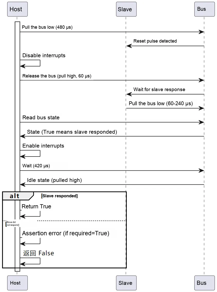
Then, we defined a method for resetting the bus, which is mainly implemented by controlling the high and low levels of the bus and adding delays; for specific details, please refer to the content of the One-Wire Communication Protocol layer we mentioned above:
def reset(self, required: bool = False) -> bool:
    """
    Reset the one-wire bus.

    Args:
        required (bool): Whether to manually trigger the assertion, default is False.

    Returns:
        bool: Returns True if the device sent a response pulse; otherwise returns False to indicate failure.

    Raises:
        AssertionError: If required is True and the device does not respond to the reset pulse.
    """
    sleep_us = time.sleep_us
    pin = self.pin
    # The host sends a reset pulse, pulling the bus low for 480us
    pin(0)
    sleep_us(480)
    # Disable interrupts to prevent interrupt service routines from interrupting the communication
    i = self.disable_irq()
    # Pull the bus high for 60us
    pin(1)
    sleep_us(60)
    # Wait for the slave to send a response pulse, which pulls the bus low for 60~240us
    # Read the bus status
    status = not pin()
    self.enable_irq(i)
    # In the idle state, the pull-up resistor pulls the bus high; the host receives the response pulse for at least 480us
    # 480us - 60us = 420us
    sleep_us(420)
    # If status on the bus is True, a device responded to the reset pulse
    # The program continues only when the assert condition is satisfied
    assert status is True or required is False, "Onewire device response"
    return status
The Sequence Diagram is shown as follows:
Then we define the methods for the host to read a single data bit, read a single byte, and read multiple bytes:
def readbit(self) -> int:
    """
    Read one data bit from the one-wire bus.

    Args:
        None

    Returns:
        int: The data bit read (0 or 1).
    """
    sleep_us = time.sleep_us
    pin = self.pin

    # For some devices, the bus needs to be pulled high before reading data to match the CRC check
    pin(1)
    # Disable interrupts
    i = self.disable_irq()
    # Pull the one-wire bus low to start reading the data bit
    # The host read signal is generated by the host pulling the bus low for at least 1us and then releasing the bus
    pin(0)
    # Skip the sleep_us(1) step for compatibility with some devices that are not strict about timing
    pin(1)
    # The host only needs to finish sampling within 15us
    sleep_us(5)
    value = pin()
    # Enable interrupts
    self.enable_irq(i)
    # The host pulls the bus high for 40us, indicating that the data bit read is complete
    sleep_us(40)
    return value

def readbyte(self) -> int:
    """
    Read one byte from the one-wire bus, implemented by calling the readbit method 8 times.

    Args:
        None

    Returns:
        int: The byte read (0~255).
    """
    value = 0
    for i in range(8):
        # Shift the return value of self.readbit() left by i bits and perform a bitwise OR with value
        # Obtain a byte made up of 8 data bits
        value |= self.readbit() << i
    return value

def readbytes(self, count: int) -> bytearray:
    """
    Read multiple bytes from the one-wire bus, implemented by calling the readbyte method multiple times.

    Args:
        count (int): Number of bytes to read.

    Returns:
        bytearray: The binary byte array read.
    """
    buf = bytearray(count)
    for i in range(count):
        buf[i] = self.readbyte()
    return buf

def readinto(self, buf: bytearray) -> None:
    """
    Read multiple bytes from the one-wire bus into a buf array.

    Args:
        buf (bytearray): Binary array in which to place the data to be read.

    Returns:
        None
    """
    for i in range(len(buf)):
        buf[i] = self.readbyte()
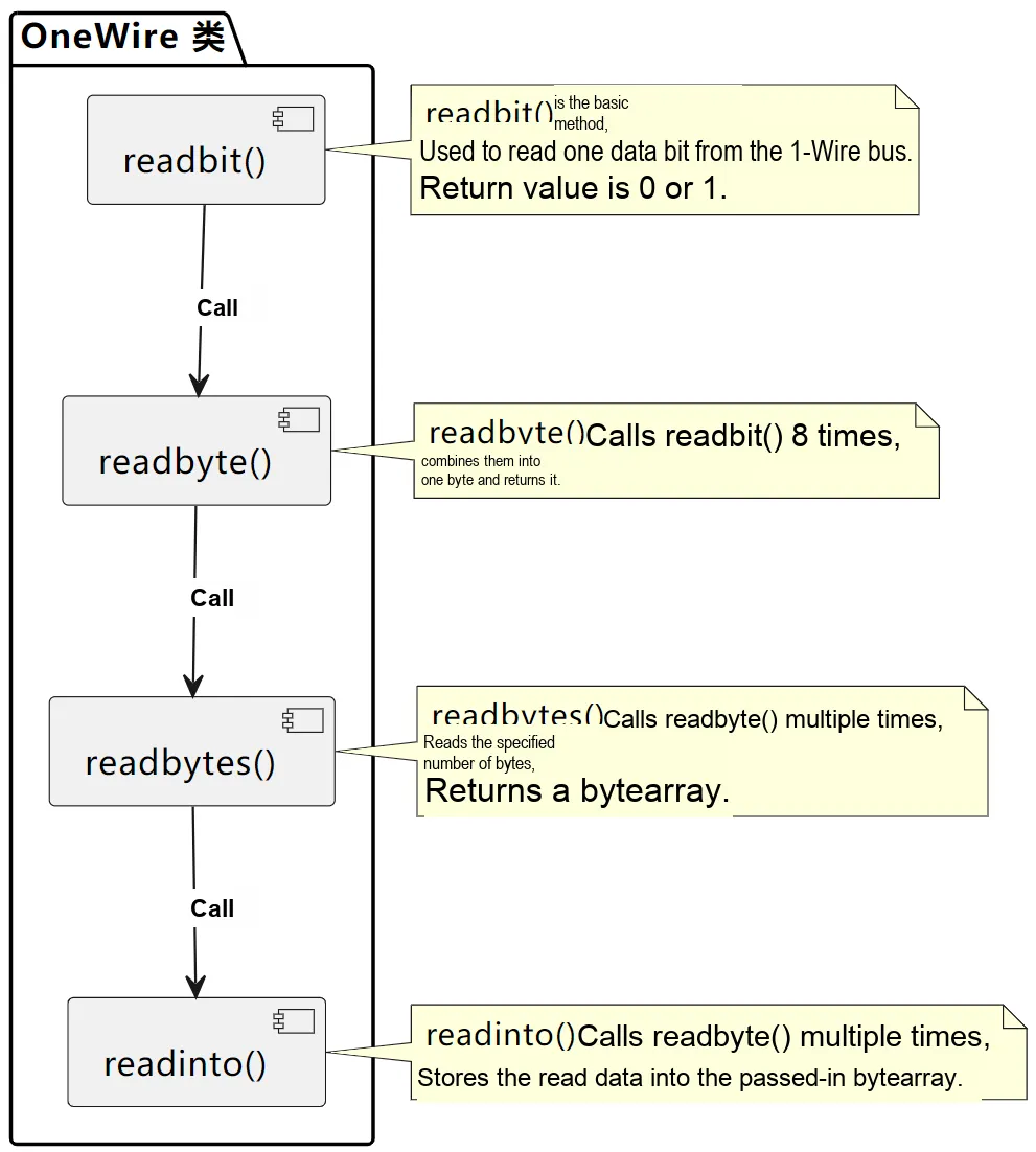
It can be seen that the readinto () method, the readbytes () method, and the readbyte () method are all implemented by calling the readbit () method:
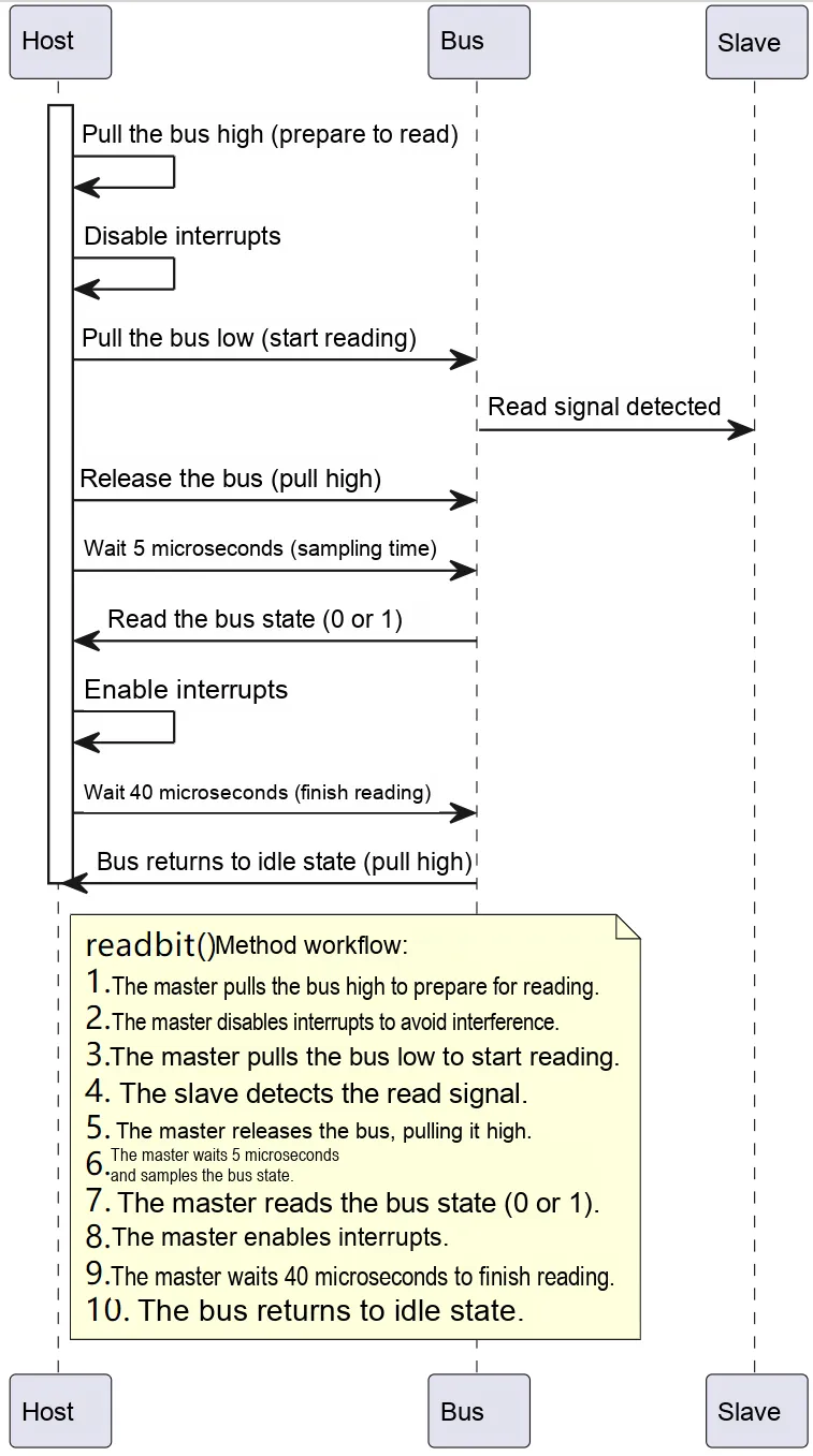
readbit () The internal working sequence of the method is shown in the following figure:
Similarly, we have defined the relevant methods for the host to write data to the sensor:
def writebit(self, value: int, powerpin: machine.Pin = None) -> None:
    """
    Write one data bit to the one-wire bus.

    Args:
        value (int): The data bit to write, 0 or 1.
        powerpin (machine.Pin): Power supply pin; this object must be passed in when parasitic power is used.
                               Independent power supply is used by default, so this pin is not needed.

    Returns:
        None
    """
    sleep_us = time.sleep_us
    pin = self.pin

    # Disable interrupts
    i = self.disable_irq()
    # First pull the bus low for at least 1us (at most 15us); this can be omitted here because MicroPython executes slowly
    # In fact, there is already a 1us delay between the two statements pin(0) and pin(value)
    pin(0)
    # If the data bit to send is 0, the bus needs to be pulled low
    # If the data bit to send is 1, the bus needs to be pulled high
    pin(value)
    # A write signal lasts at least 60us; the slave starts sampling 15us after the host pulls the bus low
    sleep_us(60)

    # If parasitic power is used and a power pin is defined
    if powerpin:
        # The one-wire bus can intermittently provide a high level to charge the slave
        pin(1)
        powerpin(self.PULLUP_ON)
    else:
        pin(1)

    # Disable interrupts
    self.enable_irq(i)

def writebyte(self, value: int, powerpin: machine.Pin = None) -> None:
    """
    Write one byte to the one-wire bus, implemented by calling the writebit method 8 times in succession.

    Args:
        value (int): The value to write, 0~255.
        powerpin (machine.Pin): Power supply pin; this object must be passed in when parasitic power is used.

    Returns:
        None
    """
    for i in range(7):
        self.writebit(value & 1)
        value >>= 1
    self.writebit(value & 1, powerpin)

def write(self, buf: bytearray) -> None:
    """
    Writes the data in the buf array to the one-wire bus by calling the writebyte method multiple times.

    Args:
        buf (bytearray): Binary array holding the data to be sent.

    Returns:
        None
    """
    for b in buf:
        self.writebyte(b)
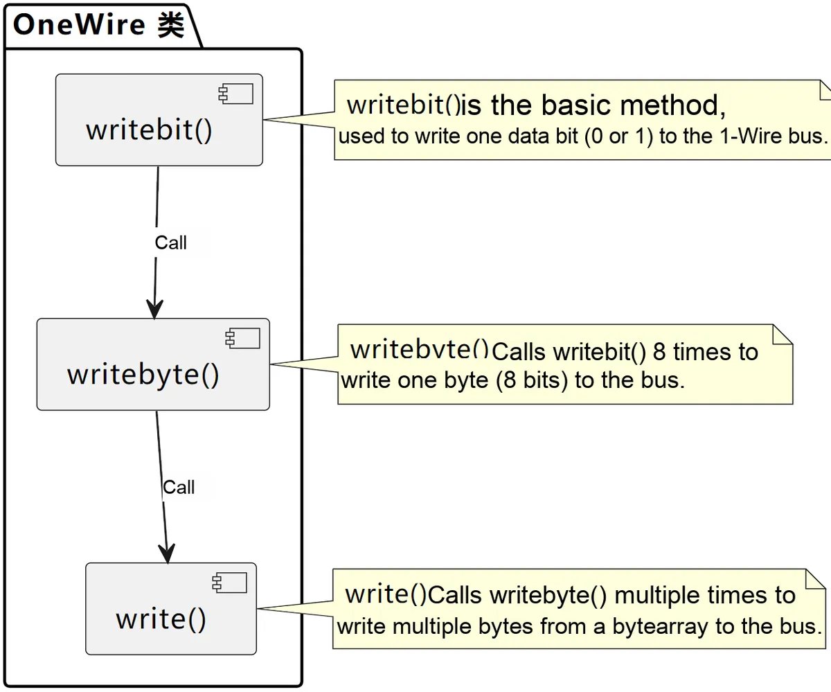
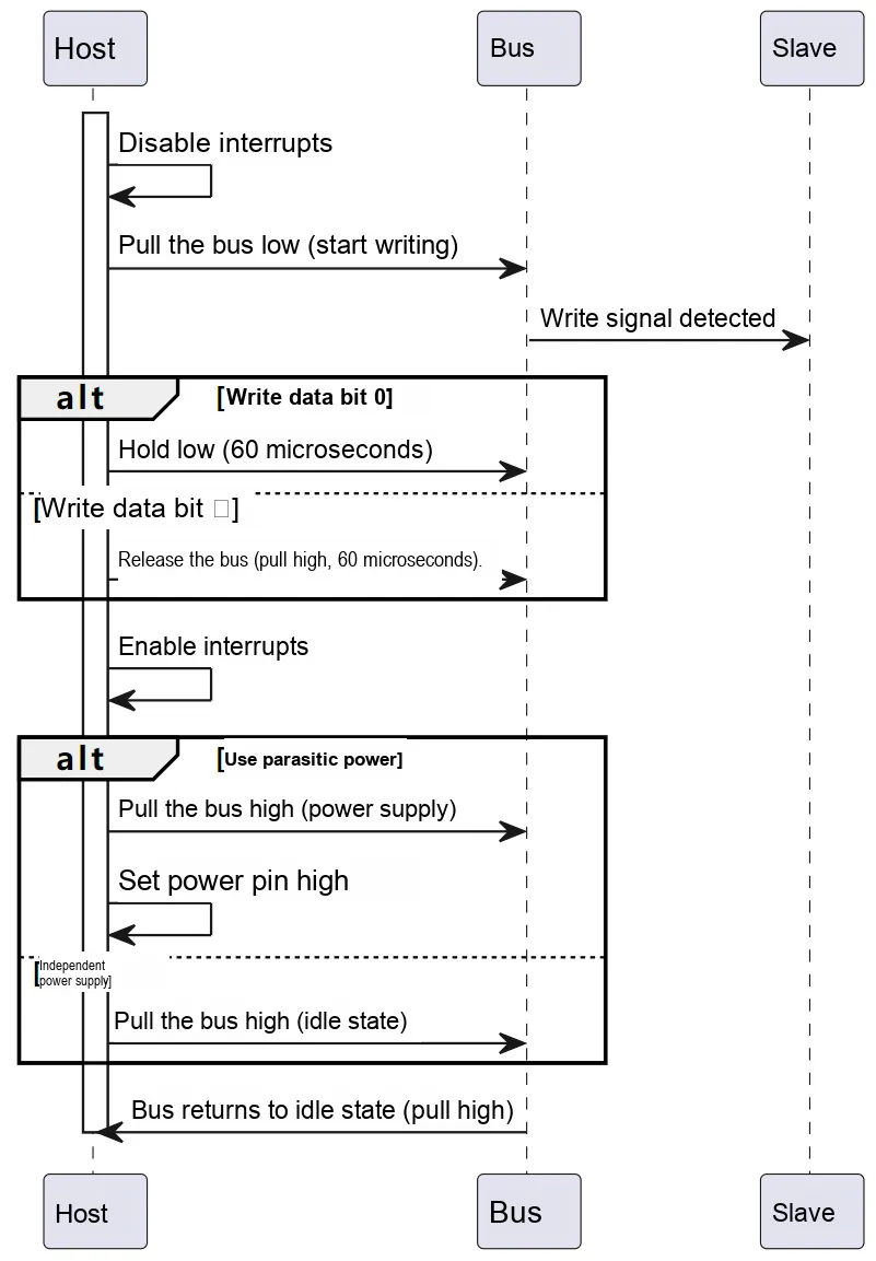
Similarly, the writebyte () method and the write () method are also implemented by calling the writebit () method:
writebit () The specific workflow of the method is shown in the following figure:
Then we defined a method for selecting a specified slave device by its ROM ID on the 1-Wire bus, which is mainly implemented by sending a match ROM ID command:
def select_rom(self, rom: bytearray) -> None:
    """
    Sends the Match ROM ID command.

    Args:
        rom (bytearray): ROM ID, a bytearray of 8 bytes, 8 bytes x 8 bits = 64 bits.

    Returns:
        None
    """
    # Initialize the bus
    self.reset()
    # Send the Match ROM ID command
    self.writebyte(OneWire.CMD_MATCHROM)
    # The host sends the ROM ID of the device to be matched in order to match the device
    self.write(rom)
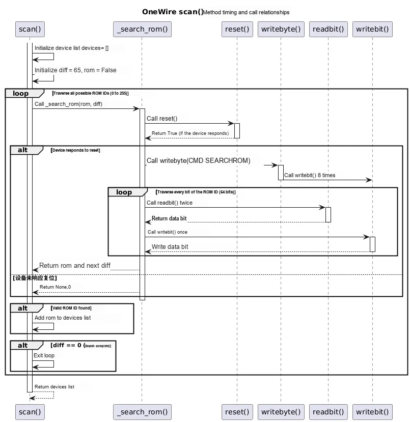
We define a scan method for finding all devices connected on the 1-Wire bus, which is mainly implemented by calling the _search_rom method:
def scan(self) -> list[bytearray]:
    """
    Scans all devices on the one-wire bus and returns all matching ROM IDs.

    Args:
        None

    Returns:
        list[bytearray]: Returns the ROM list of all connected devices.
                          Each ROM is returned as an 8-byte bytes object.
    """
    # List that stores the device ROM IDs
    devices = []
    diff = 65
    rom = False

    # Search all ROM IDs from 0 to 255
    for i in range(0xff):
        rom, diff = self._search_rom(rom, diff)
        # If the search succeeds, add the ROM ID to the list
        if rom:
            devices += [rom]
        # Indicates all devices have been searched, exit the loop
        if diff == 0:
            break
    return devices

def _search_rom(self, l_rom: bytearray, diff: int) -> tuple[bytearray, int]:
    """
    Searches the one-wire bus for the device with the corresponding ROM ID.

    Args:
        l_rom (bytearray): ROM ID found in the last search.
        diff (int): Discrepancy position of the last search.

    Returns:
        tuple[bytearray, int]: If the search succeeds, returns the ROM ID and the updated diff value.
    """

    # Reset the bus and determine whether any slave responds
    if not self.reset():
        return None, 0
    # Send the OneWire.CMD_SEARCHROM command
    self.writebyte(OneWire.CMD_SEARCHROM)
    # If no ROM ID is passed in, initialize an empty ROM ID
    if not l_rom:
        l_rom = bytearray(8)
    # Initialize the rom variable, used to store the ROM address finally found
    rom = bytearray(8)
    # Initialize the next_diff variable, used to record the next discrepancy position
    next_diff = 0
    i = 64

    # Traverse the ROM ID from low to high, 8 bytes
    for byte in range(8):
        r_b = 0
        # Read the 8 data bits of each byte of the ROM ID sent by the slave
        for bit in range(8):
            b = self.readbit()
            # Read the data bit again
            if self.readbit():
                # If both reads are 1, i.e. both are high level, the read was not successful
                if b:
                    return None, 0
            # If the two reads differ, the read was successful
            # The slave sends the original bit and the complement of each bit
            else:
                if not b:
                    # If there is a conflict and the current position is less than the discrepancy position of the last search, or the current position differs from the discrepancy position of the last search
                    if diff > i or ((l_rom[byte] & (1 << bit)) and diff != i):
                        b = 1
                        # Determine the next search direction by comparing the current search position with the discrepancy of the last search position
                        next_diff = i
            # Write the b value back to the bus; the host needs to send each bit of the ID being read
            # The slave compares the data bit read by the host and sent back with the data bit it sent, to determine whether the two match
            # Then decide whether to send the next bit
            self.writebit(b)
            if b:
                r_b |= 1 << bit
            i -= 1
        rom[byte] = r_b
    # Return the found rom value and the next discrepancy position next_diff
    return rom, next_diff
The following figure illustrates the specific process and invocation relationship:
Here, we also define the commonly used CRC-8 check method, which mainly implements fast CRC value check through XOR operations and table lookup:
def crc8(self, data: bytearray) -> int:
    """
    CRC check, implemented with a lookup table.

    Args:
        data (bytearray): Data to be checked.

    Returns:
        int: CRC check value; 0 means the match succeeded.
    """

    # Initialize the crc variable to 0
    crc = 0
    # Use a for loop to traverse each byte of the input data
    for i in range(len(data)):
       # XOR the current crc value with the current byte value and assign the result back to crc
       crc ^= data[i]
       # Take the low 4 bits of the crc value as an index and look up the corresponding value in the self.crctab1 table
       # Take the high 4 bits of the crc value as an index and look up the corresponding value in the self.crctab2 table
       # XOR the two lookup results above to get the new crc value
       crc = (self.crctab1[crc & 0x0f] ^
              self.crctab2[(crc >> 4) & 0x0f])
    return crc
3. Application Examples
3.1 Temperature and Humidity Reading of DHT11 Sensor
DHT11 digital temperature and humidity sensor is a composite temperature and humidity sensor with calibrated digital signal output. It adopts dedicated digital module acquisition technology and temperature and humidity sensing technology, which ensures that the product features high reliability and excellent long-term stability. The sensor consists of a capacitive humidity sensing element and a NTC temperature measuring element, and is connected to a high-performance 8-bit microcontroller.
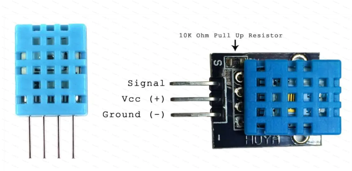
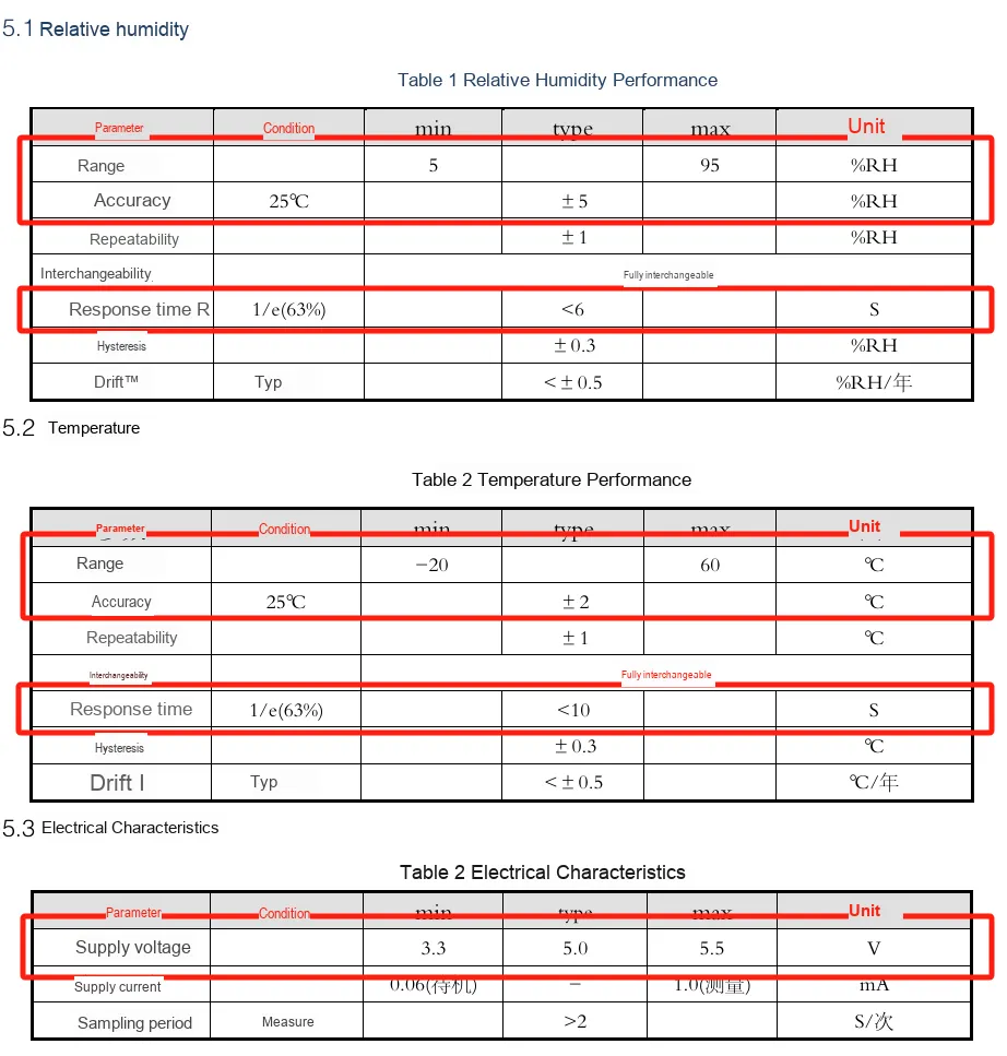
The main parameters are as follows, with the key parameters marked in red:
3.1.1 Analysis of DHT11 Sensor Communication Protocol
3.1.1.1 Data Format for Single-Bus Transmission
The definition of the 1-Wire data format is as follows:
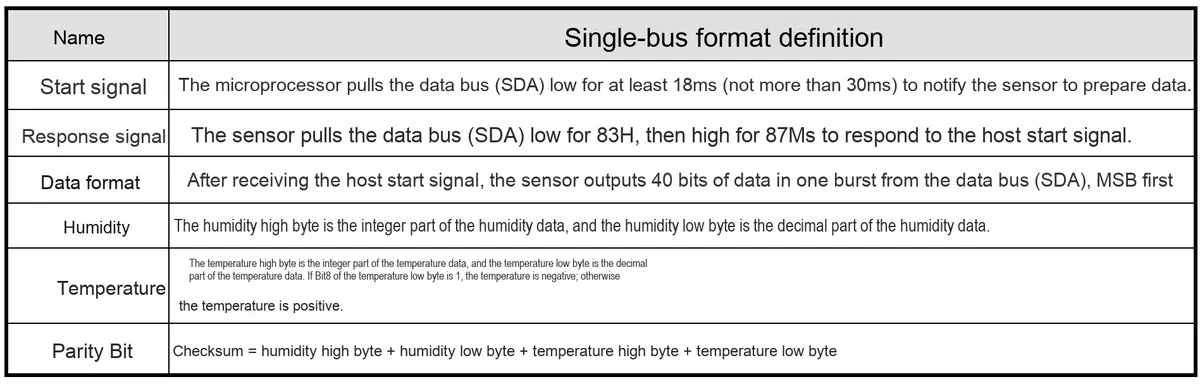
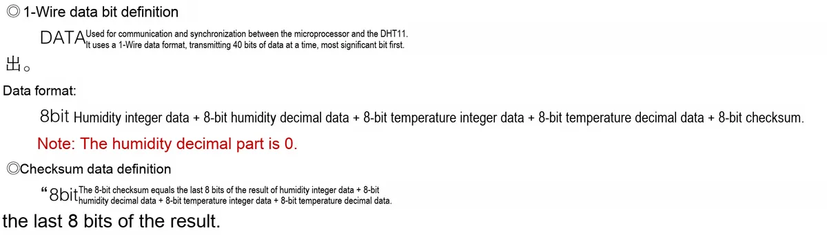
Wherein, the data format part consists of humidity data + temperature data + data check bit; the integer part and the decimal part of the temperature and humidity data each occupy 8 bits. In the transmitted data, the MSB (Most Significant Bit) comes first, which is in big-endian order, and the check bit is the 8th bit of the sum of the temperature and humidity data:
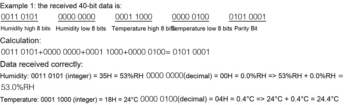
If the verification data is incorrect, it indicates that an error has occurred in data reception, so the data obtained this time needs to be discarded and the next data should be received.
Here, note that the temperature measurement range of the DHT11 sensor is -20°C to 60°C. When the transmitted temperature data is a negative value, the decimal part of the temperature data, i. e., the highest bit of the lower 8 bits of the data, will be set to 1:

3.1.1.2 1-Wire Communication Timing and Electrical Characteristics
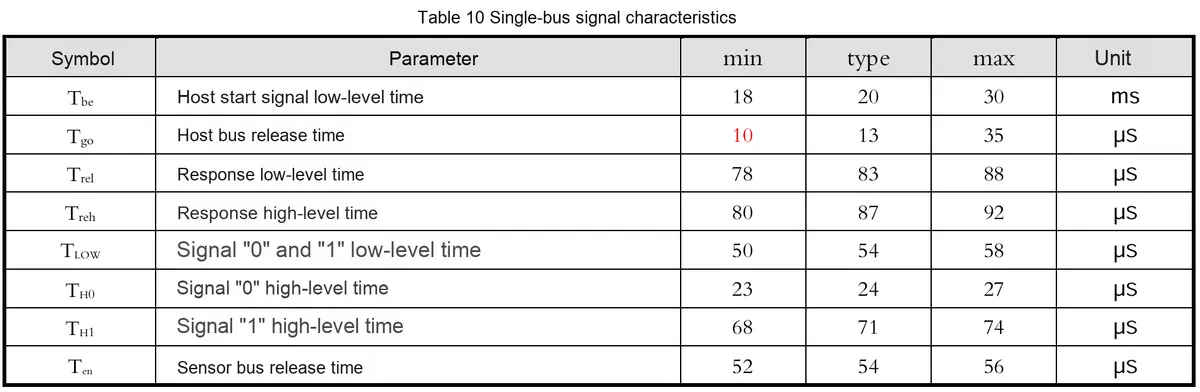
After the microcontroller sends a start signal once, the DHT11 switches from the low-power mode to the high-speed mode. Once the host's start signal ends, the DHT11 sends a response signal, transmits 40 bits of data, and triggers a single signal acquisition. The signal transmission is shown in the following figure:

3.1.1.3 Steps for Single-Chip Microcontroller to Read DHT11 Sensor
- Sensor power-on delay, idle state remains at high level:

- Master device requests slave device and waits for response:
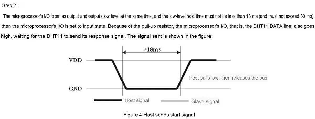
- The slave responds, and the master's IO port switches from output to input state to wait for data reception:
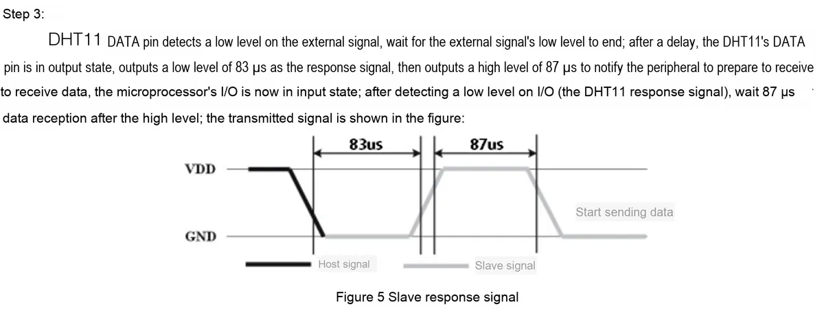
- The host receives data bit by bit:

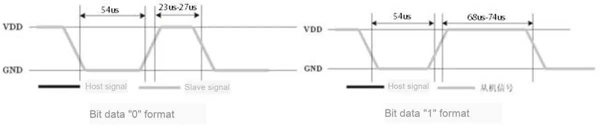
- The slave releases the bus to terminate the communication:

3.1.2 Driver Code for DHT11 Sensor
Here, first let's briefly outline the method we use to read temperature and humidity data from the DHT11 sensor:
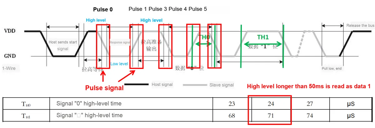
After the host sends the start signal, the host data pin switches to the input state to release the bus. From then on, all level state changes on the bus are controlled by the slave. We use the host data pin to read the high-low level changes. Here we define a high-low level change as one pulse, and record the duration that each pulse signal maintains its level after the level change. By comparing the high level duration with TH0 and TH1, we can determine whether the data bit sent by the DHT11 sensor is 0 or 1.40 bits of data correspond to 80 data pulses. Starting from the 4th pulse (inclusive), the high-level duration after every two subsequent pulses can be used as a marker to determine whether the data bit transmitted by the DHT11 sensor is 0 or 1.
Here, we first define two custom exception classes, which are used to throw exceptions when an error occurs during the data reading process of the DHT11:
# Custom exception class: checksum error
class InvalidChecksum(Exception):
    """
    InvalidChecksum exception class, used to indicate a checksum error.

    This exception is raised when data verification fails, and is typically used to detect data integrity problems such as CRC errors or other checksum errors.

    Attributes:
        message (str): Exception message describing the reason for the verification failure.
    """
    pass

# Custom exception class: data pulse count error
class InvalidPulseCount(Exception):
    """
    InvalidPulseCount exception class, used to indicate a data pulse count error.

    This exception is typically raised when the number of pulses in the signal does not match expectations, for example an abnormal pulse count during signal decoding.

    Attributes:
        message (str): Exception message describing the reason for the pulse count error.
    """
    pass
Then a class named DHT11 is defined to interact with the DHT11 temperature and humidity sensor, and some class-related variables are defined. In the constructor of the class, some instance variables are initialized, including the data bus pin connected to the DHT11 sensor, the time of the last data read, and the variables used to store temperature and humidity data.
# DHT11 temperature and humidity sensor class
class DHT11:
    """
    DHT11 class, used to read data from the DHT11 temperature and humidity sensor through a GPIO interface.
    This class encapsulates communication with the DHT11 sensor and provides methods to get temperature and humidity.
    When using this class, a GPIO pin must be provided for communicating with the sensor, and reading sensor data is supported.

    Attributes:
        pin (int): GPIO number connected to the DHT11 data pin.
        _last_measure (int): Time of the last data read, in microseconds.
        _temperature (float): Temperature data, in degrees Celsius.
        _humidity (float): Humidity data, in percent.

    Methods:
        measure(): Reads the DHT11 sensor data and updates the temperature and humidity values.
        humidity(): Gets the currently measured humidity value (unit: %RH).
        temperature(): Gets the currently measured temperature value (unit: ℃).
    """

    # Class variables related to the DHT11 sensor class:

    # Maximum count for which the pin level does not change
    MAX_UNCHANGED = const(100)
    # Interval between two data reads, in microseconds; 200000 microseconds, i.e. 200 milliseconds
    MIN_INTERVAL_US = const(200000)
    # High-level duration, in microseconds, 50 microseconds
    #   When the DHT11 sends data 1, the high-level duration is greater than 50us (typical value 71us)
    #   When the DHT11 sends data 0, the high-level duration is less than 50us (typical value 24us)
    HIGH_LEVEL = const(50)
    # Expected number of pulses, i.e. the 4 pulses generated by the slave response after initialization + the high/low-level pulses corresponding to the 40 data bits output by the DHT11
    EXPECTED_PULSES = const(84)

    def __init__(self, pin: int):
        """
        Initialize the DHT11 sensor.

        Args:
            pin (int): GPIO number connected to the DHT11 data pin.

        Returns:
            None
        """
        # Initialize instance variables, all private, not accessible from outside
        self._pin = pin
        # Record the time of the last data read
        self._last_measure = time.ticks_us()
        self._temperature = -1
        self._humidity = -1
Then, a method named measure is defined to read temperature and humidity data. First, it checks whether enough time has elapsed for the next measurement; if not, it returns directly. After that, it sends an initialization signal to the slave device and waits for the slave's response. Next, it captures the sequence of high and low level pulse durations sent by the slave and converts it into a 5-byte array. Finally, it calculates the checksum and updates the temperature and humidity data.
def measure(self) -> None:
    """
    Reads the DHT11 sensor data and updates the temperature and humidity values.

    Args:
        None

    Raises:
        InvalidChecksum: If the data checksum is wrong.
        InvalidPulseCount: If the data pulse count is wrong.
    """
    # Get the current time
    current_ticks = time.ticks_us()

    # Check whether enough time has passed for the next measurement; if not, return directly
    if time.ticks_diff(current_ticks, self._last_measure) < DHT11.MIN_INTERVAL_US and (
            self._temperature > -1 or self._humidity > -1
    ):
        return

    # Send the initialization signal to call the slave
    self._send_init_signal()
    # After the slave responds it sends data; the host's corresponding Pin switches to input mode
    # Get the sequence of high/low-level pulse durations sent by the slave
    pulses = self._capture_pulses()
    # Determine whether data 0 or 1 was sent according to the high-level duration of each data bit sent by the DHT11
    # Convert the 40-bit data sequence into a 5-byte array output
    buffer = self._convert_pulses_to_buffer(pulses)
    # Calculate the checksum; if the checksum is wrong, raise an InvalidChecksum exception
    self._verify_checksum(buffer)

    # Calculate the humidity data: integer part of humidity + fractional part
    self._humidity = buffer[0] + buffer[1] / 10
    # Calculate the temperature data: integer part of temperature + fractional part
    self._temperature = buffer[2] + buffer[3] / 10
    # Update the time of the last data read = current time
    self._last_measure = time.ticks_us()
The operation flow of this method is as follows:
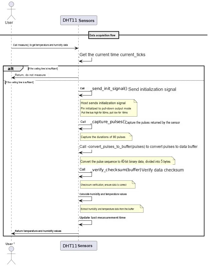
measure The method mainly calls the following methods:
- _send_init_signal Method: Sends an initialization signal to call the slave device
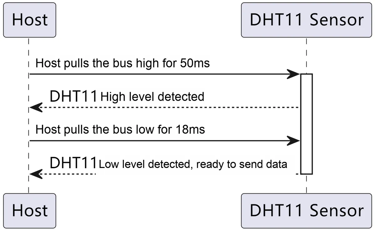
# Send the initialization signal
def _send_init_signal(self) -> None:
    """
    Sends the initialization signal to call the slave.

    Args:
        None

    Returns:
        None
    """
    # The host pin is in pull-down output mode
    self._pin.init(Pin.OUT, Pin.PULL_DOWN)
    # The host pulls the bus high for 50ms; at this time the DHT11 pin is in input state, detecting external signals
    self._pin.value(1)
    time.sleep_ms(50)
    # The host pulls the bus low for 18ms, sending the initialization signal to call the slave
    self._pin.value(0)
time.sleep_ms(18)- _capture_pulses Method: Capture the duration sequence of the 80 pulses returned by the DHT11 sensor
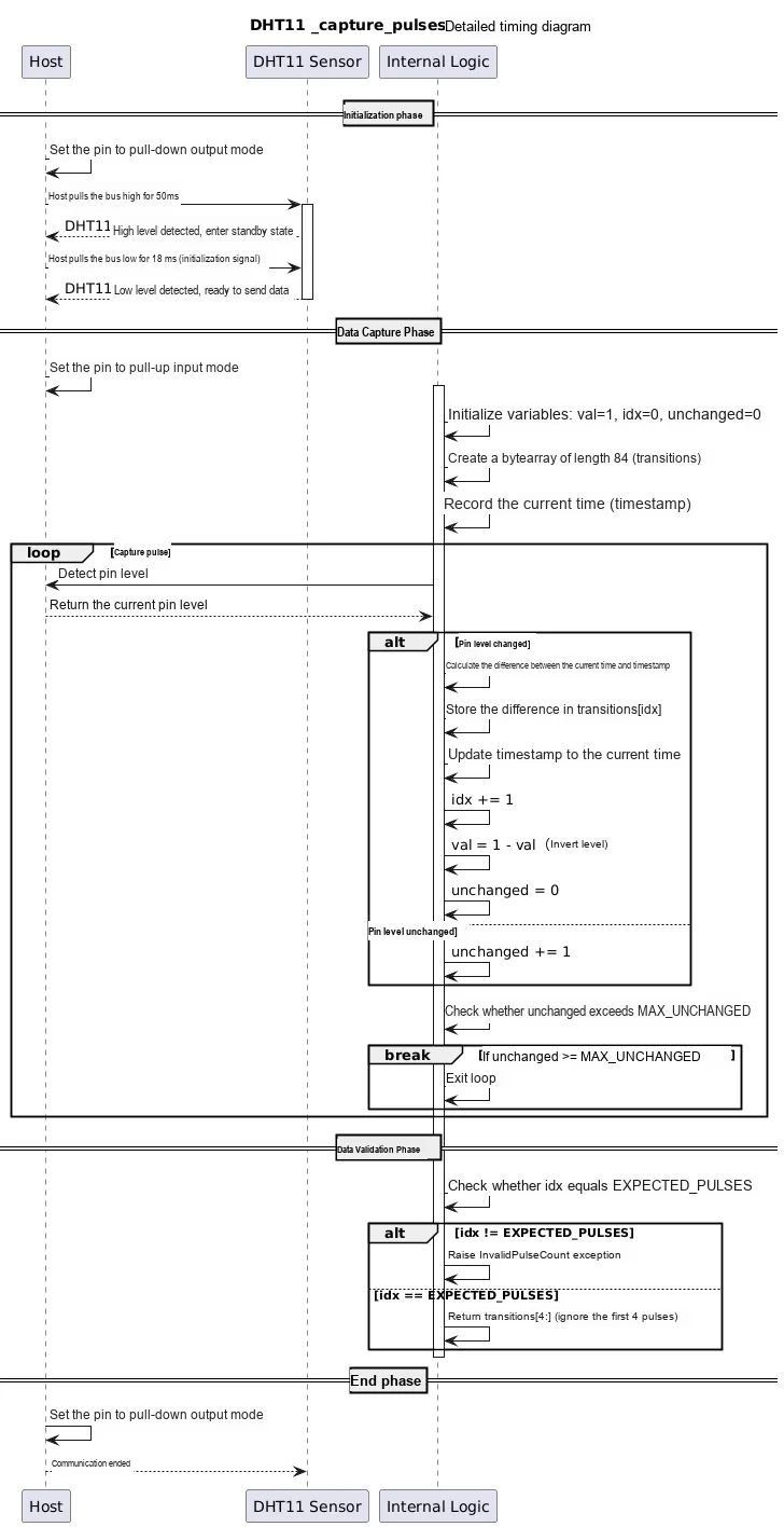
# Capture the sequence of durations of the 80 pulses returned by the DHT11 sensor
# Use the @micropython.native decorator to compile the method to machine code and improve running efficiency
@micropython.native
def _capture_pulses(self) -> bytearray:
    """
    Captures the sequence of durations of the 80 pulses returned by the DHT11 sensor.

    Returns:
        bytearray: Sequence of high/low-level pulse durations.

    Raises:
        InvalidPulseCount: If the number of captured pulses is incorrect.
    """

    # Convert the pin to pull-up input mode
    pin = self._pin
    pin.init(Pin.IN, Pin.PULL_UP)

    # Temporary variable recording the pin level
    val = 1
    # Counter variable for high/low-level pulses
    idx = 0

    # Create an empty array to store 84 pulses
    # Where:
    #       The first 4 pulses are generated by the slave response
    #       The last 80 pulses are data bits
    transitions = bytearray(DHT11.EXPECTED_PULSES)
    # Variable recording the number of times the pin level has not changed
    unchanged = 0
    # Record the current time
    timestamp = time.ticks_us()

    # Exit the loop when the number of times the pin level stays unchanged exceeds DHT11.MAX_UNCHANGED
    while unchanged < DHT11.MAX_UNCHANGED:
        # Detect whether the pin level has changed
        if val != pin.value():
            # When idx is greater than DHT11.EXPECTED_PULSES, the number of captured pulses is wrong
            # Raise an InvalidPulseCount exception
            if idx >= DHT11.EXPECTED_PULSES:
                raise InvalidPulseCount(
                    "Got more than {} pulses".format(DHT11.EXPECTED_PULSES)
                )
            now = time.ticks_us()
            # The transitions binary sequence records the durations of the pulse sequence
            transitions[idx] = now - timestamp
            timestamp = now
            # Increment idx
            idx += 1
            # val is equivalent to a negation operation
            val = 1 - val
            unchanged = 0
        else:
            # The pin level has not changed; increment the unchanged count by 1
            unchanged += 1
    # After data reception is complete, the host switches to pull-down output mode to end communication
    pin.init(Pin.OUT, Pin.PULL_DOWN)
    # Determine whether the number of received pulses is the expected number of pulses
    if idx != DHT11.EXPECTED_PULSES:
        # If not, raise an InvalidPulseCount exception
        raise InvalidPulseCount(
            "Expected {} but got {} pulses".format(DHT11.EXPECTED_PULSES, idx)
        )
    # Return the last 80 bytes of the captured pulse duration sequence
    # Ignore the first 4 bytes, i.e. the 4 pulses generated by the slave response
return transitions[4:]- _convert_pulses_to_buffer Method: Converts the captured pulse sequence into a 5-byte array
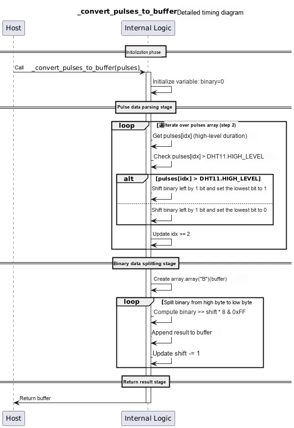
# Use the @micropython.native decorator to compile the method to machine code and improve running efficiency
@micropython.native
def _convert_pulses_to_buffer(self, pulses: bytearray) -> array.array:
    """
    Converts the captured pulse sequence into a 5-byte array.

    Args:
        pulses (bytearray): Binary array corresponding to the pulse sequence.

    Returns:
        array.array: 5-byte array: humidity integer value, humidity decimal value, temperature integer value, temperature decimal value, checksum.
    """
    # Convert the last 80 bytes of the captured pulse duration sequence into the corresponding binary data
    binary = 0

    # Determine whether the transmitted binary data is 0 or 1 from the high-level duration
    #   When the DHT11 sends data 1, the high-level duration is greater than 50us (typical value 71us)
    #   When the DHT11 sends data 0, the high-level duration is less than 50us (typical value 24us)

    # range(0, len(pulses), 2) means start at index 0 and increment by 2 each time until the length of the pulses list is reached
    # This code iterates over all elements at odd indices of the pulses list
    for idx in range(0, len(pulses), 2):
        # Shift the current binary value left by one bit, and compare the element at the corresponding index of the pulses list with DHT11.HIGH_LEVEL:
        #   If it is greater than DHT11.HIGH_LEVEL, add 1 to binary
        #   Otherwise, add 0 to binary
        # This process concatenates the binary data in the pulses list to form a 40-bit binary number
        binary = binary << 1 | int(pulses[idx] > DHT11.HIGH_LEVEL)

    # Split the 40-bit binary number into 5 bytes and add them to the buffer array

    # Create an array whose elements are of unsigned byte type
    buffer = array.array("B")
    # The shift variable represents the number of bits of the binary number to extract
    # range(4, -1, -1) means start at 4 and decrement by 1 each time until -1 is reached
    # Uses a reverse loop from 4 to 0, which means it extracts data from the highest bits down to the lowest bits
    for shift in range(4, -1, -1):
        # Shift binary right by shift*8 bits, then AND it with 0xFF to get the lowest 8 bits
        # Obtain an integer between 0 and 255 and add it to the buffer list
        buffer.append(binary >> shift * 8 & 0xFF)
return buffer- _verify_checksum Method: Verify the checksum
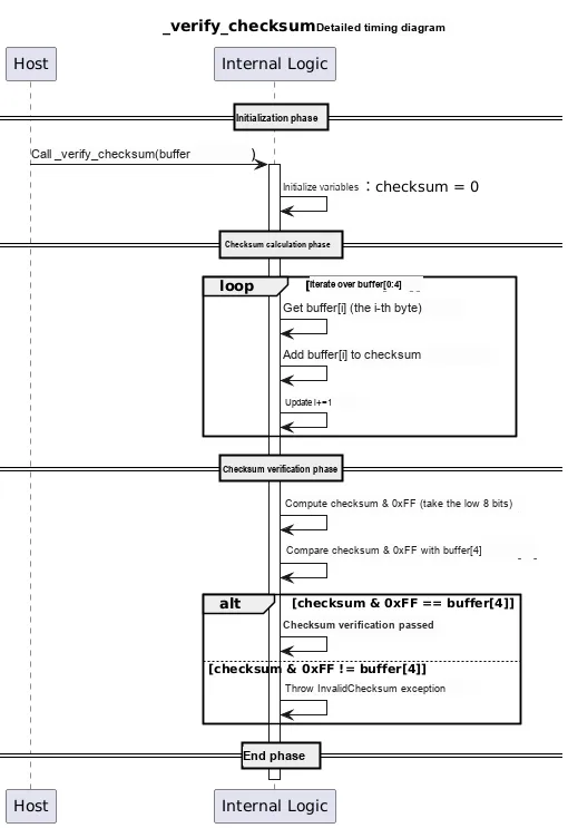
# Use the @micropython.native decorator to compile the method to machine code and improve running efficiency
@micropython.native
def _verify_checksum(self, buffer: array.array) -> None:
    """
    Verify the checksum.

    Args:
        buffer (array.array): The array corresponding to the 40 bits of data sent by the DHT11.

    Returns:
        None

    Raises:
        InvalidChecksum: If checksum verification fails.
    """

    checksum = 0
    for buf in buffer[0:4]:
        # Accumulate the checksum
        checksum += buf
    # Compare the low 8 bits of the received data checksum with buffer[4], the checksum sent by the DHT11 slave
    if checksum & 0xFF != buffer[4]:
        # If they are not equal, raise an InvalidChecksum exception
        raise InvalidChecksum()
For the function of acquiring temperature and humidity data, we have defined two methods here, which are decorated with the @property decorator. In this way, we can call these methods just like accessing object properties without explicit invocation, and these two methods actually call the measure () method to obtain data. :
# Get the humidity data
# @property is a decorator that converts a method into a property accessor
@property
def humidity(self) -> float:
    """
    Get the humidity data.

    This method uses the @property decorator, so it can be accessed like an object attribute without explicitly calling the method.

    Args:
        None

    Returns:
        float: The currently measured humidity value (unit: %RH).

    Raises:
        InvalidChecksum: If the data checksum is wrong.
        InvalidPulseCount: If the data pulse count is wrong.
    """
    self.measure()
    return self._humidity

# Get the temperature data
@property
def temperature(self) -> float:
    """
    Get the temperature data.

    This method uses the @property decorator, so it can be accessed like an object attribute without explicitly calling the method.

    Args:
        None

    Returns:
        float: The currently measured temperature value (unit: ℃).

    Raises:
        InvalidChecksum: If the data checksum is wrong.
        InvalidPulseCount: If the data pulse count is wrong.
    """
    self.measure()
    return self._temperature
3.1.3 Application Experiment
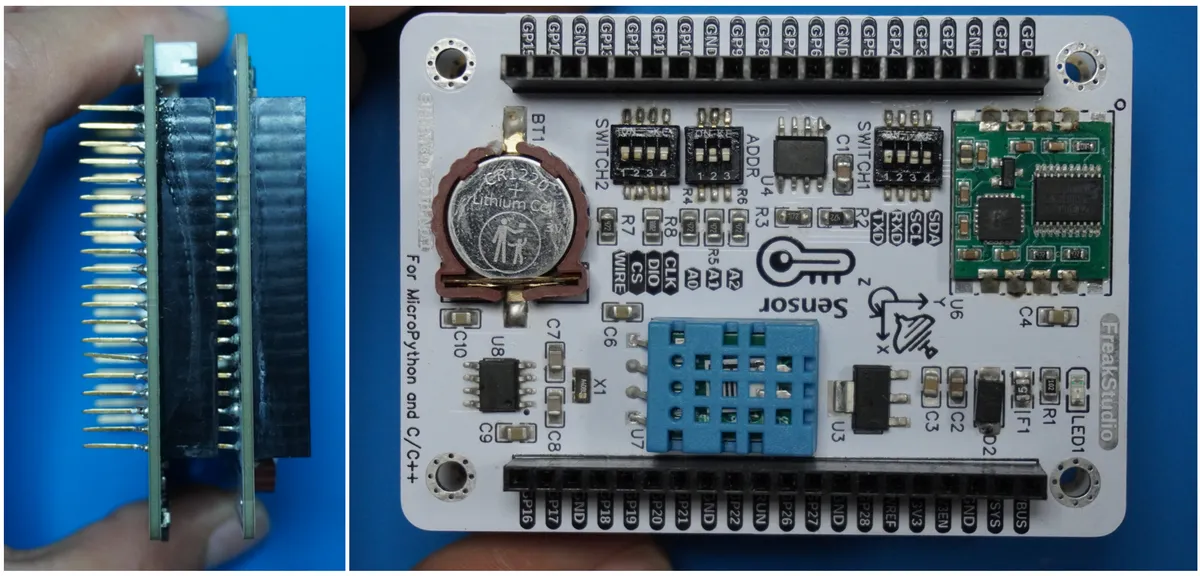
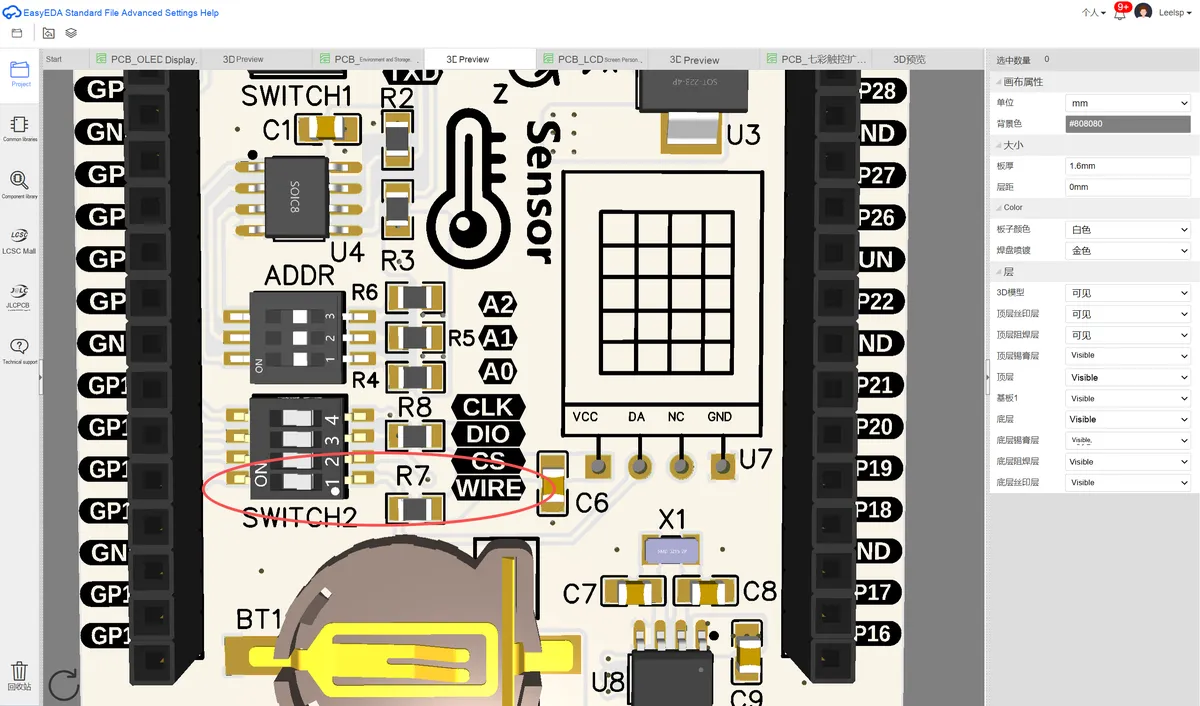
First, we need to insert the Fengya No. 1 Board - Environment and Storage Acquisition Board into the Fengya No. 1 Board - Universal Compatible Expansion Board, and at the same time turn on the WIRE option of the SWITCH2 DIP switch on the Fengya No. 1 Board - Environment and Storage Acquisition Board:
The pins used are shown in the following table:
Pico pins | DHT11 Pin |
GP13 | DATA |
VBUS | VCC |
GND | GND |
Here, we use GP13 to connect to the data bus of the DHT11, and a 4.7K pull-up resistor is connected to the data bus. It should be noted that:
- When reading the temperature and humidity values, it is necessary to perform two consecutive readings to obtain real-time data, as the value read each time is actually the result of the previous measurement.
- Accurate data can be obtained as long as the interval between each sensor reading is longer than 2 seconds, and it is not recommended to read the sensor multiple times in succession.
- Prolonged exposure to direct sunlight or intense ultraviolet radiation will degrade the sensor's performance.
- Avoid leaving components in environments with condensation, excessive dryness, or acidic gases for a long period of time.
- The relative humidity of gas is greatly affected by temperature, so this sensor needs to ensure that the temperature is approximately constant when measuring relative humidity at different times.
The following code can be found in the elegance-devkit v1\Demo\37 OneWire_DHT11 folder of the resource package we provide.
In the main program section, we first declare two global variables for storing temperature and humidity data:
# ======================================== Global Variables ============================================

# Humidity data
humidity = 0.0
# Temperature data
temperature = 0.0
In the initialization configuration, we instantiate the pins used by the data lines:
# ======================================== Initialization ==========================================


# Delay to wait for the device to initialize
time.sleep(3)
# Print debug information
print('FreakStudio : Using OneWire to read DHT11 sensor')

# Delay 1 s, wait for the DHT11 sensor to finish powering up
time.sleep(1)
# Initialize the one-wire communication pin, pull-down output
DHT11_PIN = Pin(13, Pin.OUT, Pin.PULL_DOWN)
# Initialize the DHT11 instance
dht11 = DHT11(DHT11_PIN)
In the main program section, we periodically read the temperature and humidity data:
# ========================================  Main Program  ============================================

while True:
    # Read the temperature and humidity data
    temperature = dht11.temperature
    humidity = dht11.humidity
    # Print the temperature and humidity data
    print("temperature: {}℃, humidity: {}%".format(temperature, humidity))
    # Wait 2 seconds
    utime.sleep(2)
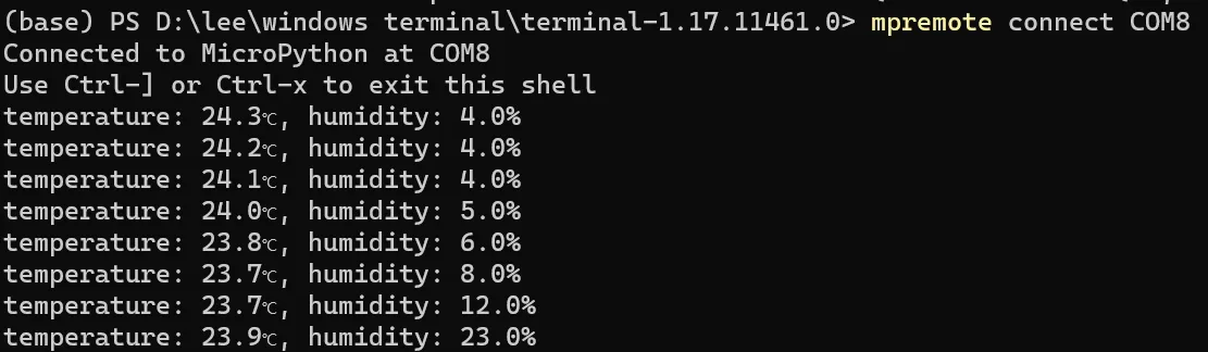
Burn the code to the Raspberry Pi Pico, open the remote port, and you can see the following output from the Raspberry Pi Pico:
We used a lighter to burn beside the DHT11 sensor while the sensor was in operation:
3.1 Application Experiment.mp4 30.0 MB
It can be seen that the temperature of the DHT11 sensor changes slightly and very slowly. In fact, the DHT11 sensor is not suitable for measuring absolute temperature and absolute humidity, but for measuring relative temperature and relative humidity, and it has the following disadvantages:
- Low accuracy:
DHT11temperature and humidity sensor is less accurate than some high-end sensors, with a temperature accuracy of ±2°C and a humidity accuracy of ±5%RH. - Long response time:
The DHT11temperature and humidity sensor has a long response time, which requires a certain period to stably output data, making it unsuitable for some application scenarios that have high requirements for real-time performance. - Limited transmission distance:
The DHT11temperature and humidity sensor has a relatively short transmission distance, generally within a range of several meters; if long-distance data transmission is required, other methods need to be adopted.
3.2 MY18E20 Temperature Reading
MY18E20 is a high-precision programmable digital single-bus temperature measurement chip:
- Its temperature measurement range is from -55°C to + 125°C, with a maximum resolution of 0.015°C
- The maximum deviation is ±0.5°C within the range of -10°C to + 85°C, and the maximum error at extreme operating temperatures is less than ±1.5°C
- The chip has a built-in 80-bit non-volatile memory cell for storing user-defined information, such as high and low temperature alarm thresholds, sensor node IDs, location information, temperature calibration data, etc.
A microprocessor can configure parameters such as temperature measurement accuracy and alarm thresholds by reading from and writing to the chip's control registers via a GPIO port in accordance with software instructions of the 1-Wire protocol, and periodically collect digital temperature data.
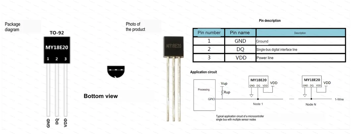
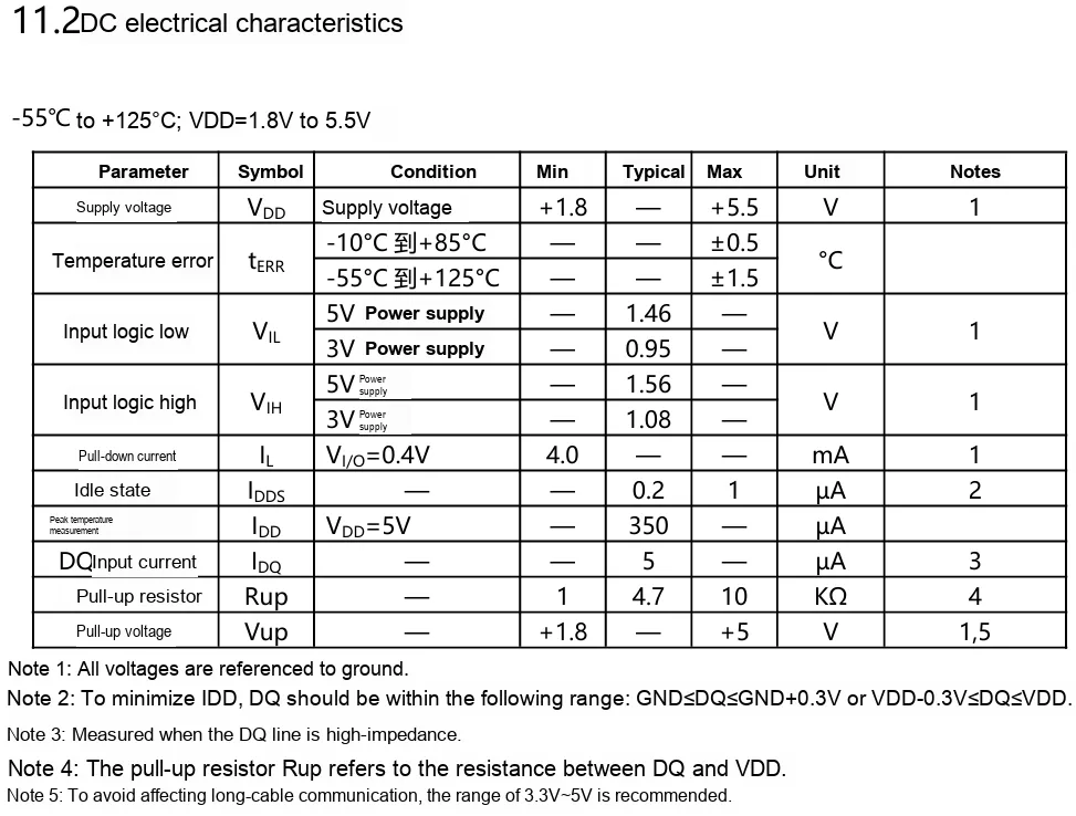
3.2.1 Analysis of MY18E20 Sensor Communication Protocol
It should be noted that some terms related to 1-Wire communication in the datasheet are different from the terms we use, but they refer to the same objects:
- Host/Device/Controller: refers to the single-chip microcomputer that initiates communication in 1-Wire communication.
- Slave/Chip/Sensor: Refers to a sensor that responds to communication in 1-Wire communication.
- Read slot: refers to the communication process in which the host sends a read signal.
- Write cycle: refers to the communication process in which the host transmits a write signal.
- Reset Signal / Call Signal: Initiated by the host, which pulls the bus low for a certain period before releasing it and waiting for a response from the slave.
- Presence Signal/Response Signal: After the master initiates a call signal, the slave detects a rising edge on the bus and pulls the bus low for a period of time.
3.2.1.1 Structure and Working Principle of MY18E20 Sensor
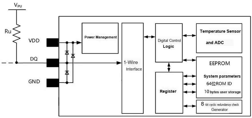
The MY18E20 sensor mainly consists of the following components:
- EEPROM: It mainly stores system parameters, a 64-bit ROM ID, and 10-byte user storage space, and the 64-bit ROM holds the unique ID sequence code of the device.
The single-chip microcontroller (master) identifies and addresses devices on the bus via the unique 64-bit code of each device. Since every device has a unique code, there is theoretically no limit to the number of devices that can be connected to the bus and addressed.
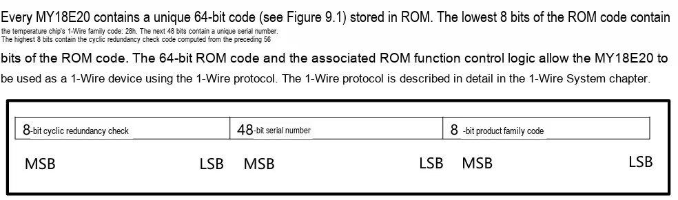
- 8-bit Cyclic Redundancy Check Generator: The Cyclic Redundancy Check byte is part of the 64-bit ROM code of the MY18E20, located in the 9th byte of the scratchpad. The Cyclic Redundancy Check of the ROM code is calculated from the first 56 bits of the ROM code and stored in the highest bits of the ROM. The Cyclic Redundancy Check code of the scratchpad is calculated inside the scratchpad, so it changes as the data in the scratchpad changes. The Cyclic Redundancy Check code provides the host with a data verification method when reading data from the scratchpad.To verify whether data is read correctly, the host must perform calculations on its own using the received data, then compare the resulting value against the Cyclic Redundancy Check code stored in the ROM (from a ROM read operation) or the Cyclic Redundancy Check code in the scratchpad register (from a scratchpad read operation). If the calculated Cyclic Redundancy Check code matches the one read out, the data has been received correctly without errors.
- Temperature Sensor and ADC Unit: Performs temperature measurement and data conversion, and the generated temperature data is stored in the temperature register of the scratchpad.
- Numerical control logic: Perform corresponding operations based on the received ROM instructions and function instructions.
- Register: The register contains a two-byte temperature register that stores the digital output from the temperature sensor.
In addition, the register provides two alarm trigger threshold registers (TH and TL), one high and one low. The configuration register allows the user to set the resolution of temperature digital conversion to 9,10,11, or 12 bits (corresponding to temperature resolutions of 0.5°C, 0.25°C, 0.125°C, and 0.0625°C respectively, with a default of 12-bit resolution). An additional data space is provided for user use.
The configuration-related data in the register can be stored in the non-volatile EEPROM, so the data will not be lost when the chip is powered off; when the device is powered on next time, the configuration-related data in the EEPROM will be automatically written into the register.
- 1-Wire interface: converts the command data received by the 1-Wire interface and sends it to the digital control logic unit.
- Power Management: It converts the input voltage and distributes the power to each system for operation.
The working steps of MY18E20 can be divided into three phases:
- Initializing MY18E20: Power on and initialize the MY18E20 chip, the master sends a call signal, and the slave MY18E20 responds
- The host sends a ROM command (followed by any necessary data exchange): Access each DS18B20, search for the 64-bit serial number, read the matching serial number value, and then match the corresponding DS18B20. If we only use a single DS18B20, we can directly skip the ROM command, and the byte for skipping the ROM command is 0xCC.
Here, follow any necessary data exchange operations including host reset bus, sending function commands, reading data, etc.
- Execute the MY18E20 function instruction (followed by any necessary data exchange): including commands such as reading temperature values, writing alarm trigger thresholds, and configuring temperature measurement accuracy.
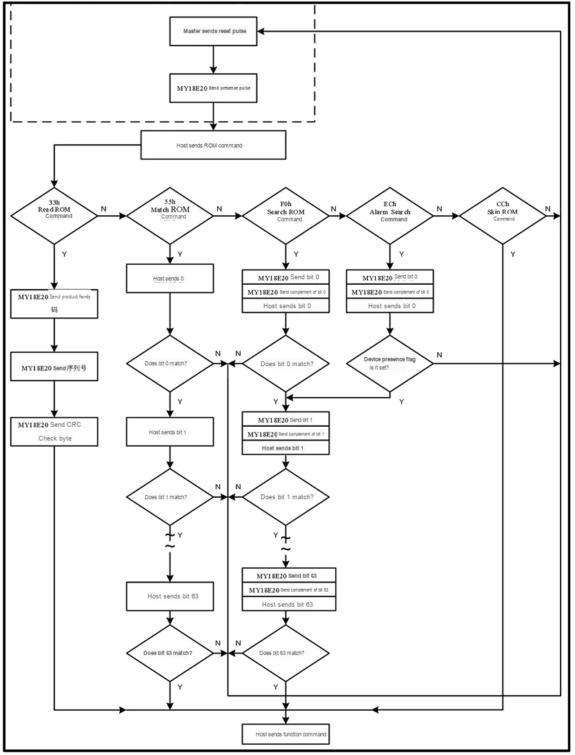
When the bus master detects the slave response signal, it can send ROM commands. There are 5 ROM commands in total, each 8 bits long. It should be noted that the master must send a ROM command before sending the function command of the MY18E20:
ROM Instruction Type | Command Description |
SEARCHROM[F0h] |  |
Read ROM[33h] |  |
Match ROM[55h] |  |
Skip ROM[CCh] |  |
Alarm Search [ECh] |  |
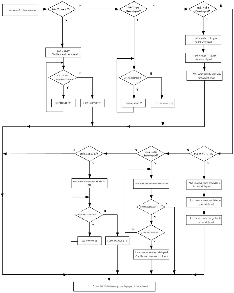
After the bus host addresses a MY18E20 that it intends to communicate with using a ROM command, the host can issue one of the function commands for the MY18E20. These commands allow the host to perform data read and write operations, including commands such as reading temperature values, writing alarm trigger thresholds, and configuring temperature measurement accuracy.
Function Instruction Type | Command Description |
CONVERTT[44h] |  |
WRITE SCRATCHPAD[4Eh] |  |
WRITE USER[66h] |  |
READ SCRATCHPAD[BEh] |  |
COPY SCRATCHPAD[48h] |  |
RECALL E2[B8h] |  |
READ POWER SUPPLY[B4h] |  |
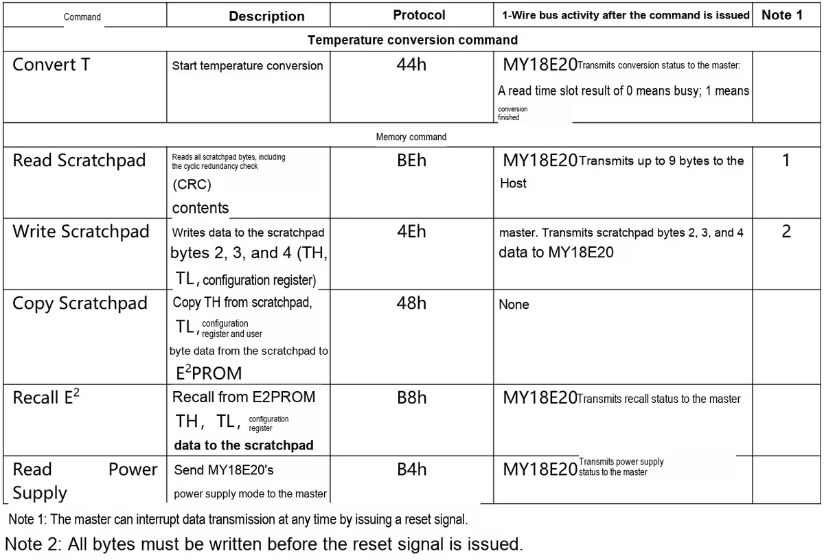
Here, the Copy Scratchpad [48h] instruction and the Recall E2 [B8h] instruction are mainly used in the following scenarios:
When we set the TH alarm upper threshold, TL alarm lower threshold and temperature conversion resolution into the scratchpad, we expect the configured data to be retained after the device is powered off, and be read from the last configuration back into the scratchpad when the device is powered on next time. At this point, to transfer the TH, TL and configuration data from the scratchpad to the E2PROM, the master must issue the Copy Scratchpad [48h] command. The data in the E2PROM register is retained during power loss and is automatically loaded into the corresponding scratchpad location upon power-up.Data can also be reloaded at any time via the RecallE2[B8h] command. The host can send a read slot following the RecallE2[B8h] command, and the chip will then return a status: it returns 0 if the reload is still in progress, and 1 if the reload has been completed.
The ROM instruction flowchart is as follows:
The functional instruction flowchart is as follows:
3.2.1.1 Memory Organization of MY18E20
MY18E20 's memory consists of a SRAM scratchpad register and a non-volatile E2PROM register. The memory organization of MY18E20 is shown in the following figure:
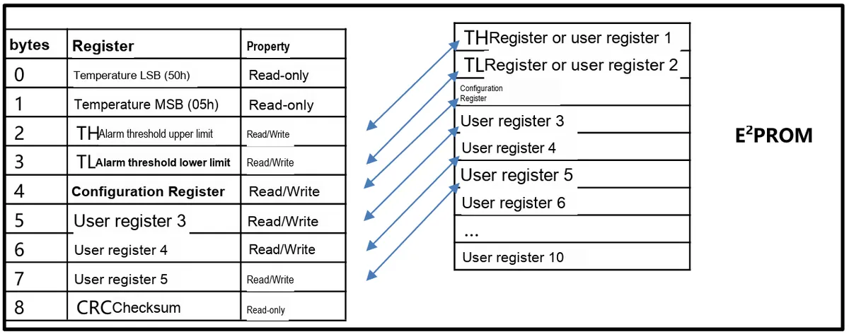
Wherein:
- Bytes 0 and 1 are read-only: used to store the converted temperature data
- Bytes 2 and 3 are used to access the TH and TL registers: store the upper and lower temperature limits for the alarm
- Byte 4 contains configuration register data: which is used to configure the temperature conversion accuracy
- Bytes 5,6 and 7 are readable and writable: provide data space for users to use
- Byte 8 is a read-only register: Cyclic redundancy check code generated by bytes 0 to 7
Data can be written to bytes 2,3, 4,5, 6 and 7 via the WriteScratchpad[4Eh]and WriteUser [66h]commands. Data transmission must start from the least significant bit (LSB) of byte 2 (i. e., the host sends data from LSB to MSB). To verify data integrity, the scratchpad can be read after the write operation (via the Read Scratchpad [BEh]command). When reading the scratchpad, 1-Wire data transmission starts from the least significant bit of byte 0 (i. e., the slave sends data from LSB to MSB).
3.2.1.2 MY18E20 Sensor Application Circuit
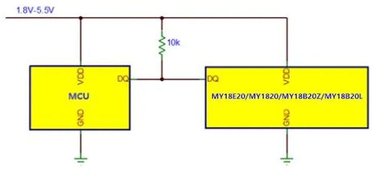
The MY18E20 is powered by an external power supply via the VDD pin, as shown in the diagram below. The advantage of this mode is that no MOSFET pull-up is required, and the 1-Wire bus can freely perform other operations during temperature conversion.

3.2.1.3 1-Wire Bus Communication Timing and Electrical Characteristics
3.2.1.3.1 Master sends call signal and slave responds
3.2.1.3.2 Host Read/Write Data Bits

3.2.1.4 Direct Temperature Measurement Function
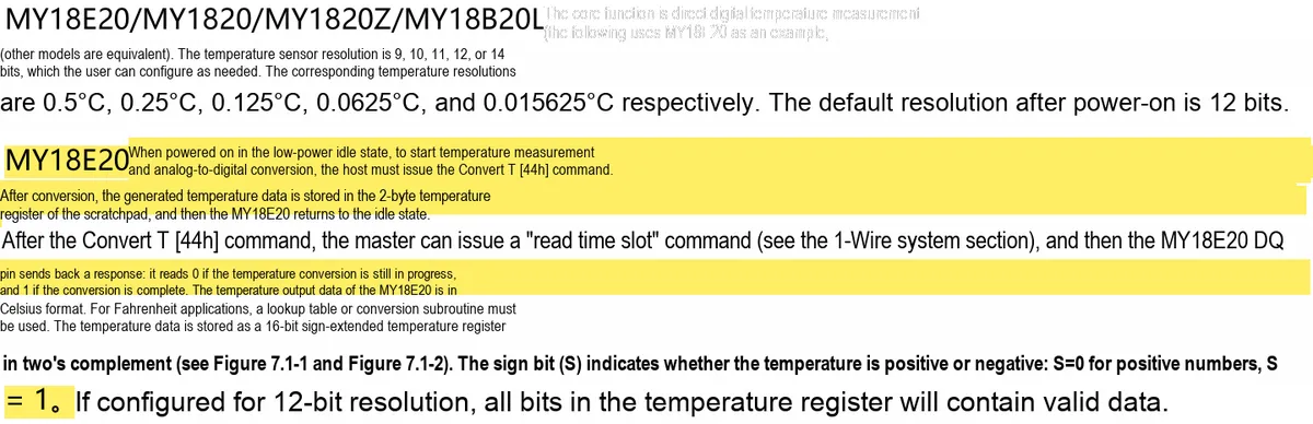
MY18E20 stores temperature data in the form of 16-bit two's complement, and the temperature unit is degree Celsius. After the temperature conversion command is issued, the temperature value obtained through conversion is stored in the 0th and 1st bytes of the register in the form of a two-byte two's complement.
The five S bits in the high byte are sign bits: S = 1 when the temperature is positive, and S = 0 when the temperature is negative.
The remaining 11 bits are temperature data bits:
- For 12-bit resolution: all bits are fully valid
- For 11-bit resolution: Bit 0 is undefined
- For 10-bit resolution: Bits 0 and 1 are undefined
- For 9-bit resolution: Bits 0,1 and 2 are undefined
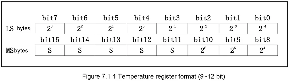
It should be noted that the temperature is transmitted in big-endian order, that is, the most significant (MS) byte comes first, followed by the least significant (LS) byte.

The temperature calculation method is as follows:
- When the five sign bits S = 0, the temperature is positive: directly convert the following 11-bit binary to decimal, then multiply by 0.0625 (12-bit resolution) to obtain the temperature value
- When the five sign bits S= 1, the temperature is a negative value: First convert the subsequent 11-bit two's complement to the original code (keep the sign bit unchanged, invert the value bits and add 1), then calculate the decimal value, and multiply it by 0.0625 (12-bit resolution) to obtain the temperature value.
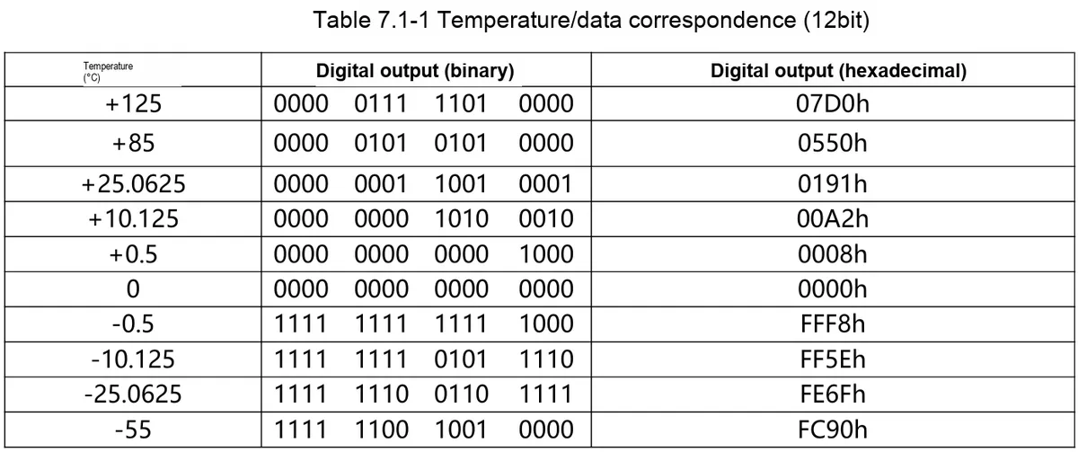
Take the above table as an example to explain the temperature calculation:
- Digital output at + 125°C
07D0(00000111 11010000), when converted to decimal, is2000, and the corresponding temperature in degrees Celsius is:0.0625×2000 = 125°C - The digital output at -55°C is
FC90. First invert it bitwise, then add 1, and the converted original code is:11111011 01101111. The numeric part converted to decimal is870, and the corresponding temperature in Celsius is:-0.0625×870 = -55°C
3.2.1.5 Temperature Acquisition Resolution Configuration
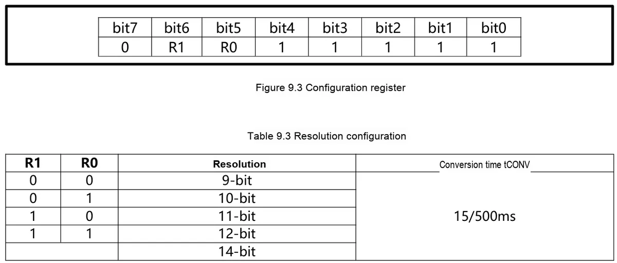
In the configuration register, we can set the conversion resolution of the ME18E20 via R0 and R1. After power-on, the ME18E20 defaults to R0= 1 and R1= 1 (12-bit resolution), and bit 7 and bits 0 to 4 in the register are reserved for internal device use.
3.2.1.6 Alarm Function
After the MY18E20 completes a temperature conversion, it compares the resulting temperature value with a user-defined two's complement alarm trigger value stored in the TH and TL registers. These TH and TL registers are non-volatile (E2PROM), meaning the data is retained even when the device is powered off. The TH and TL registers can be accessed via the second and third bytes of the scratchpad.
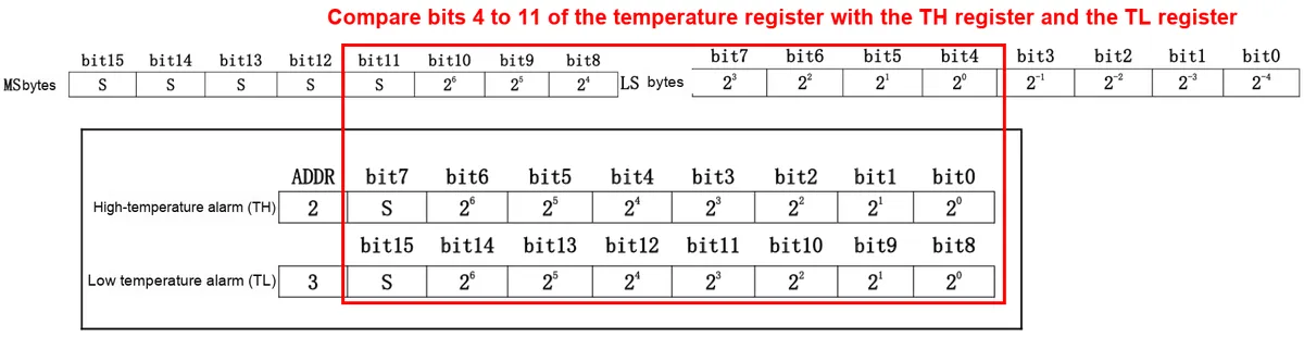
Since TH and TL are 8-bit registers, only bits 11 to 4 are used in temperature comparison. If the measured temperature is less than or equal to TL or greater than or equal to TH, the alarm condition is established, and a flag bit will be set inside the chip. This flag bit is updated with each temperature measurement, so if the alarm condition is no longer satisfied, the flag bit will be cleared after the next temperature conversion.
The host can issue a AlarmSearch[ECh]command to check the flag status of all temperature chips connected to the bus. Any chip with its flag set will respond to this command, allowing the host to identify which specific chip has entered an alarm condition. If the alarm condition is valid and the TH or TL setting has been modified, an additional temperature conversion should be performed to verify the alarm condition.
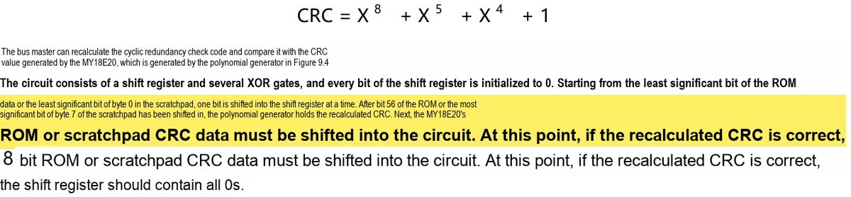
3.2.1.7 Cyclic Redundancy Check Code Generation
The Cyclic Redundancy Check byte is a component of the 64-bit ROM code of MY18E20, and it is located at the 9th byte of the scratchpad. The ROM code Cyclic Redundancy Check is calculated from the first 56 bits of the ROM code and stored in the most significant bits of the ROM. The Cyclic Redundancy Check code of the scratchpad is calculated inside the scratchpad and thus changes as the data in the scratchpad changes. The Cyclic Redundancy Check code provides the host with a data verification method when reading data from the scratchpad.To verify whether data reading is correct, the host must perform calculation on its own based on the received data, and then compare this data with the Cyclic Redundancy Check code in the ROM (from the ROM read operation) or with the Cyclic Redundancy Check code in the scratchpad register (from the scratchpad register read operation). If the calculated Cyclic Redundancy Check code matches the read one, the data has been received correctly. The Cyclic Redundancy Check comparison and whether to continue the operation are entirely up to the host. If the Cyclic Redundancy Check of the chip (ROM or scratchpad register) does not match the value calculated by the bus host, there is no circuit inside the chip to prevent further execution of the instruction.
The calculation method of CRC check code is as follows:
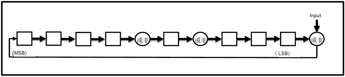
CRC Lookup Table Method
When we perform actual coding, since the computation load of the Cyclic Redundancy Check value generated by the CRC polynomial is excessively large, we usually adopt the CRC look-up table method to calculate the CRC check value. Simply put, we store the CRC check values corresponding to different pieces of data in a table (that is, data corresponds to the index, and the CRC check value corresponds to the element value at the index), so as to quickly compute the CRC check code through table lookup and XOR operations. For the specific principle, please refer to the following link:
The Most Detailed and Easy-to-Understand CRC-16 Checksum Principle (With Source Code Attached)
https://www.cnblogs.com/94cool/p/3559585.html
The CRC look-up table method is applicable to scenarios requiring frequent CRC calculation, such as data transmission and storage. Its drawback is that it requires a certain amount of storage space to store the precomputed Look up table.
3.2.2 MY18E20 Sensor Driver Code
Here, since the operating procedure of the MY18E20 sensor is compatible with that of the DS18B20 sensor, we can directly use the driver code for the DS18B20 sensor. First, we define a DS18X20 class (there are many different models of DS18 series temperature sensors, and their communication processes are generally similar), and the main functions of this class are as follows:
- Initialization: When initializing the
DS18X20class, an instance of theOneWireclass needs to be passed in; through composition, theDS18X20class can use the methods of the OneWire class for 1-Wire communication. - Set the power supply mode: Two power supply modes are supported, including independent power supply and parasitic power supply. In the parasitic power supply mode, it is required to supply power to the sensor through the
powerpinpin. - Scan Sensor: Scans all
DS18X20sensors on the 1-Wire bus and returns a list of their ROM addresses. - Start temperature conversion: To start the temperature conversion operation, send the temperature conversion command
CMD_CONVERTto implement it. - Read and write scratchpad registers: Read and write the scratchpad register data of the sensor, including configuration information such as temperature value and resolution.
- Calculate and return temperature values: Read the temperature value of the sensor, support three units: Celsius, Fahrenheit and Kelvin, and perform different temperature calculations according to the sensor model (
DS18B20,DS18S20, etc.). - Set temperature resolution: Set the resolution for temperature conversion; settings between 9-bit and 12-bit are supported.
Here, the DS18X20 class and the OneWire class adopt a composition relationship instead of an inheritance relationship:
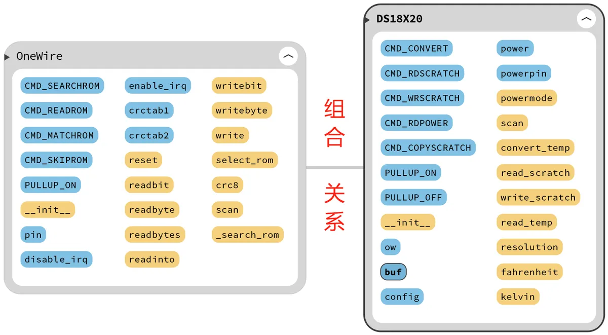
It is mainly based on the following considerations:
- Single Responsibility Principle:
OneWireclass focuses on the underlying implementation of 1-Wire communication and provides a series of basic operations such as data reading and writing, and reset.The DS18X20class focuses on the upper-layer logic for theDS18X20temperature sensor, such as temperature conversion and temperature reading, and encapsulates the specific commands of theDS18X20sensor (e. g., the temperature conversion commandCMD_CONVERT, the scratchpad read commandCMD_RDSCRATCH, etc.).- Such a design follows the Single Responsibility Principle, enabling the two classes to have a clear division of labor and distinct responsibilities.
- Reusability:
The OneWireclass is a general-purpose 1-Wire communication class that can be reused by multiple device classes, such as other types of 1-Wire devices.- If an inheritance relationship is adopted,
the DS18X20class will be excessively coupled with theOneWireclass, which reduces the reusability of theOneWireclass
- Flexibility:
- In a composition relationship,
the DS18X20class can freely choose which instance of theOneWireclass to use, and configure it according to actual requirements. - And if an inheritance relationship is adopted,
the DS18X20class must inherit from theOneWireclass, making it impossible to freely choose which 1-Wire communication class to use.
- In a composition relationship,
- Testability:
- In a compositional relationship,
the DS18X20class can be tested independently of theOneWireclass, which helps improve test coverage and reliability. - If an inheritance relationship is adopted,
the DS18X20class will have its relevant tests coupled with the implementation details of theOneWireclass, which reduces the independence of the tests.
- In a compositional relationship,
Here, we first define DS18X20 the function command constants and initialization method used by the sensor:
# Define the DS18X20 temperature sensor class
class DS18X20:
    """
    DS18X20 temperature sensor class, used to communicate with one-wire temperature sensors such as the DS18B20 and DS18S20.
    This class encapsulates the functions of the temperature sensor, including temperature conversion, temperature reading, and resolution setting.

    Attributes:
        ow (OneWire): An instance of the one-wire communication class.
        buf (bytearray): Buffer used to store scratchpad data (9 bytes).
        config (bytearray): Buffer used to store user configuration data (3 bytes).
        power (int): Power mode, 1 for external power supply, 0 for parasitic power supply.
        powerpin (machine.Pin): Power supply pin object (used in parasitic power mode).

    Methods:
        powermode(powerpin: machine.Pin) -> int: Set the power mode of the DS18X20.
        scan() -> list[bytearray]: Scan the one-wire bus for DS18X20 sensors and return a list of ROM addresses.
        convert_temp(rom: bytearray) -> None: Start the sensor temperature conversion.
        read_scratch(rom: bytearray) -> bytearray: Read the sensor scratchpad data.
        write_scratch(rom: bytearray, buf: bytearray) -> None: Write the sensor scratchpad data.
        read_temp(rom: bytearray) -> float: Read the sensor temperature.
        resolution(rom: bytearray, bits: int) -> int: Set or read the sensor temperature conversion resolution.
        fahrenheit(celsius: float) -> float: Convert degrees Celsius to degrees Fahrenheit.
        kelvin(celsius: float) -> float: Convert degrees Celsius to kelvins.
    """

    # DS18X20 function commands
    CMD_CONVERT     = const(0x44)   # Convert temperature command
    CMD_RDSCRATCH   = const(0xbe)   # Read scratchpad command
    CMD_WRSCRATCH   = const(0x4e)   # Write scratchpad command
    CMD_RDPOWER     = const(0xb4)   # Read power supply command
    CMD_COPYSCRATCH = const(0x48)   # Copy scratchpad command

    # Pull-up resistor control
    PULLUP_ON       = const(1)
    PULLUP_OFF      = const(0)

    def __init__(self, onewire: OneWire) -> None:
        """
        Initialize the DS18X20 class, passing in the one-wire communication class to use.

        Args:
            onewire (OneWire): An instance of the one-wire communication class.
        """
        self.ow = onewire
        # Store the 9 bytes of scratchpad data
        self.buf = bytearray(9)
        # Store the 3 bytes of user configuration data
        self.config = bytearray(3)
        # External power supply by default
        self.power = 1
        self.powerpin = None
Then, a method for setting the power supply mode of the DS18X20 temperature sensor is defined as follows:
def powermode(self, powerpin: Pin = None) -> int:
    """
    Set the power mode of the DS18X20.

    Args:
        powerpin (machine.Pin): Power supply pin object (used in parasitic power mode). If None, the default mode is used.

    Returns:
        int: Power mode, 1 for external power supply, 0 for parasitic power supply.
    """
    # If powerpin has been set, pull it low to turn off the pull-up resistor
    if self.powerpin is not None:
        self.powerpin(DS18X20.PULLUP_OFF)

    # Send the CMD_SKIPROM command
    self.ow.writebyte(OneWire.CMD_SKIPROM)
    # Send the read power mode command
    self.ow.writebyte(DS18X20.CMD_RDPOWER)
    # Read the power mode
    self.power = self.ow.readbit()

    # After reading is done, set powerpin to push-pull output mode and pull it low
    if powerpin is not None:
        assert type(powerpin) is Pin, "powerpin must be a Pin object"
        self.powerpin = powerpin
        self.powerpin.init(mode=Pin.OUT, value=0)

    # Return the power mode
    return self.power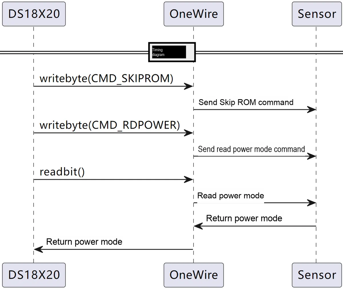
As can be seen, its core implementation relies on OneWire instances to send and receive commands.
Meanwhile, the scan () method is defined to scan the DS18X20 temperature sensors connected to the single bus and return a list of their ROM addresses, which can be used in subsequent operations such as reading temperature values or configuring sensor parameters.
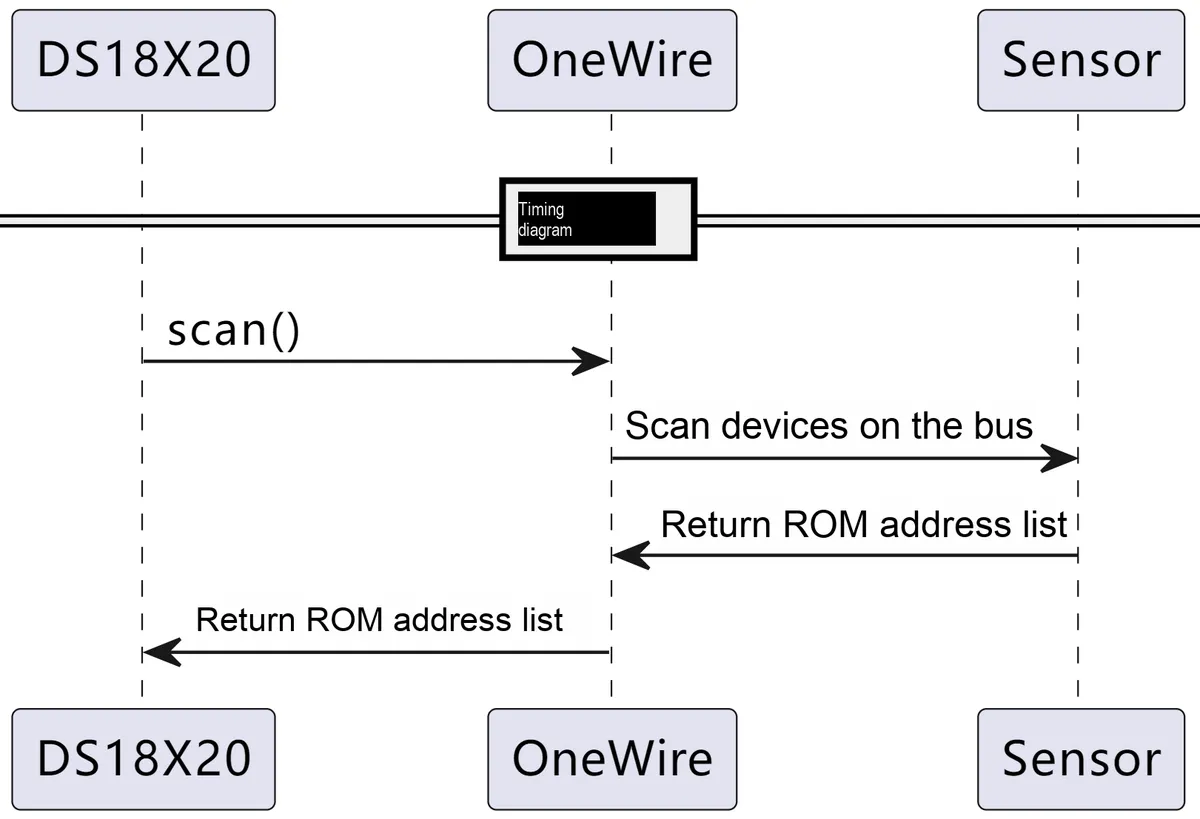
By checking the first few bytes of the ROM address, the DS18X20 series temperature sensors can be identified and distinguished from other devices that may be connected to the bus.
def scan(self) -> list[bytearray]:
    """
    Scan the one-wire bus for DS18X20 sensors and return a list of ROM addresses.

    Args:
        None

    Returns:
        list[bytearray]: List of sensor ROMs, each ROM is an 8-byte bytearray.
    """
    if self.powerpin is not None:
        self.powerpin(DS18X20.PULLUP_OFF)

    # From the ROM list obtained by scanning the one-wire bus, select the ROMs that start with 0x10, 0x22 or 0x28
    return [rom for rom in self.ow.scan() if rom[0] in (0x10, 0x22, 0x28)]
The core method of the DS18X20 series is the convert_temp () method, which is used to initiate the temperature conversion operation of the DS18X20 temperature sensor.
It should be noted that calling this method only initiates the temperature conversion operation and does not directly return the temperature value. To obtain the temperature value after the conversion is completed, you need to call read_temp () method.
def convert_temp(self, rom: bytearray = None) -> None:
    """
    Start the sensor temperature conversion.

    Args:
        rom (bytearray): ROM address of the target temperature sensor. If None, broadcast to all sensors.

    Returns:
        None
    """
    if self.powerpin is not None:
        self.powerpin(DS18X20.PULLUP_OFF)
    # The host resets the bus
    self.ow.reset()
    # When rom is not empty, send the CMD_SKIPROM command
    # When there is only one temperature sensor on the bus, the CMD_SKIPROM command can be sent
    if rom is None:
        self.ow.writebyte(OneWire.CMD_SKIPROM)
    else:
        # Select the corresponding sensor by the given ROM address
        self.ow.select_rom(rom)
    # Write the convert temperature command
    self.ow.writebyte(DS18X20.CMD_CONVERT, self.powerpin)
The specific process is shown in the following figure:
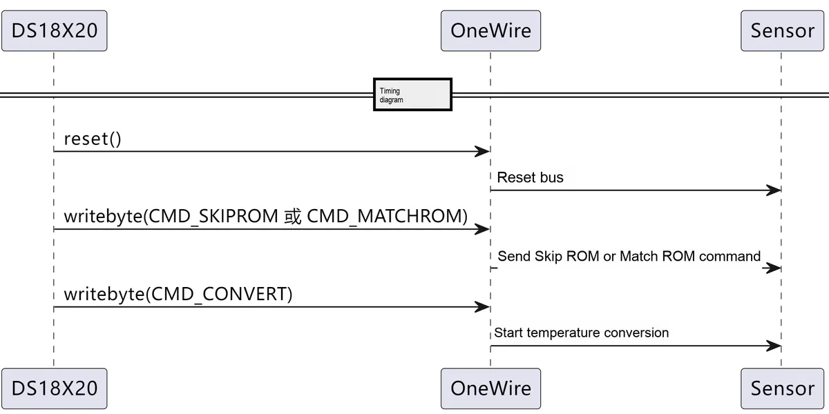
Then, we defined the method for reading and writing the scratch registers, which store temperature data, user-defined data and relevant configuration data (such as temperature conversion resolution, upper and lower alarm thresholds, etc.):
def read_scratch(self, rom: bytearray) -> bytearray:
    """
    Read the sensor scratchpad data.

    Args:
        rom (bytearray): ROM address of the target temperature sensor.

    Returns:
        bytearray: Scratchpad data (9 bytes).

    Raises:
        AssertionError: If the CRC check fails.
    """
    if self.powerpin is not None:
        self.powerpin(DS18X20.PULLUP_OFF)
    # The host resets the bus
    self.ow.reset()
    # Select the corresponding sensor by the given ROM address
    self.ow.select_rom(rom)
    # Write the CMD_RDSCRATCH command
    self.ow.writebyte(DS18X20.CMD_RDSCRATCH)
    # Read the scratchpad data and save it to buf
    self.ow.readinto(self.buf)
    # Perform the CRC check
    assert self.ow.crc8(self.buf) == 0, 'CRC error'
    return self.buf

def write_scratch(self, rom: bytearray, buf: bytearray) -> None:
    """
    Write the sensor scratchpad data.

    Args:
        rom (bytearray): ROM address of the target temperature sensor.
        buf (bytearray): Data to write to the scratchpad (9 bytes).

    Returns:
        None
    """
    if self.powerpin is not None:
        self.powerpin(DS18X20.PULLUP_OFF)
    # The host resets the bus
    self.ow.reset()
    # Select the corresponding sensor by the given ROM address
    self.ow.select_rom(rom)
    # Write the CMD_WRSCRATCH command
    self.ow.writebyte(DS18X20.CMD_WRSCRATCH)
    # Write the scratchpad data
    self.ow.write(buf)
It should be noted that before reading from or writing to the scratchpad register, the 1-Wire bus will first be reset, and the corresponding sensor will be selected according to the given ROM address:
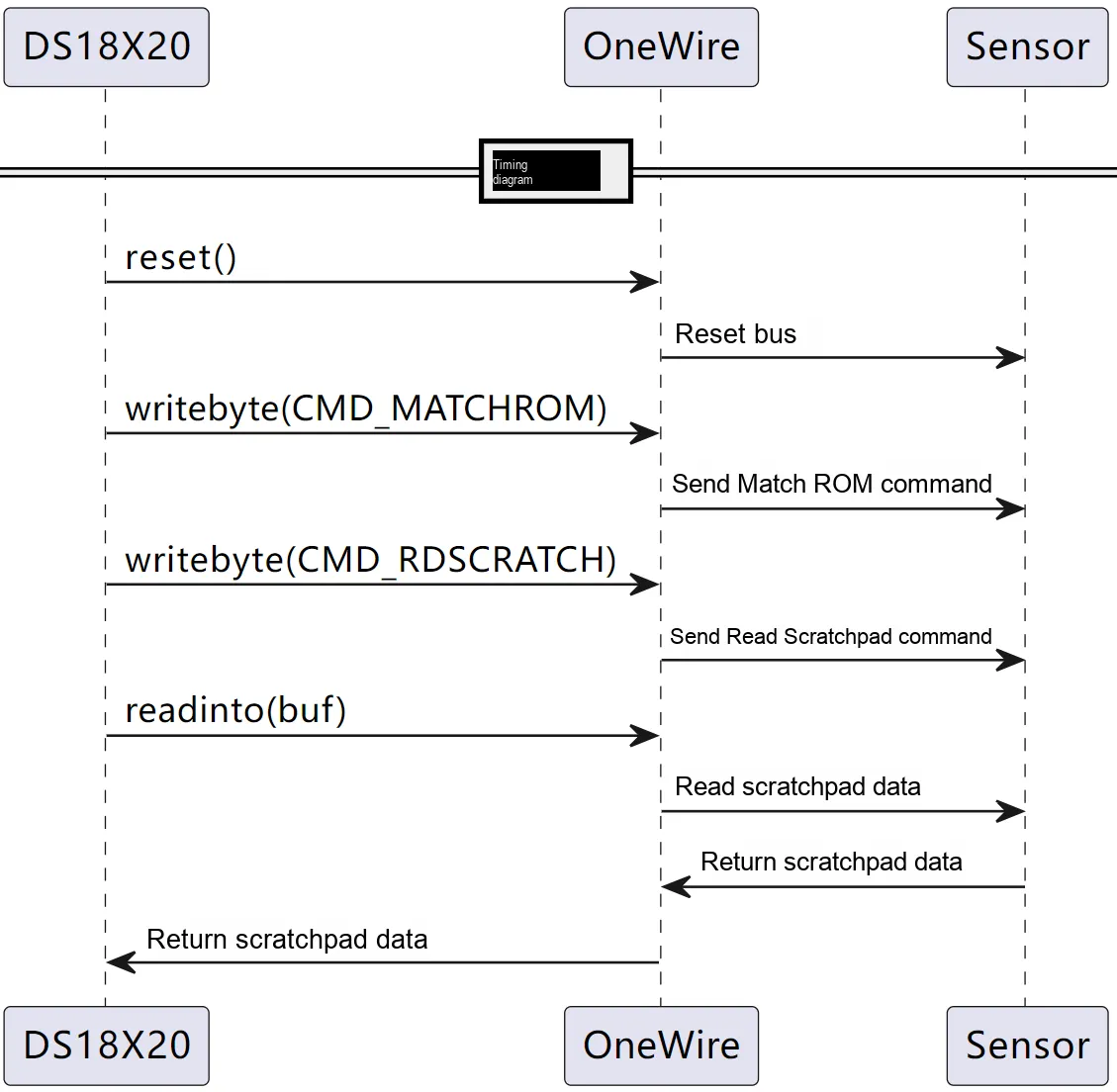
Then, we defined the read_temp () method for reading temperature data, which is mainly implemented by reading and writing the scratchpad registers. It should be noted that this method also performs CRC check to ensure that the read data is complete and reliable; if the CRC check fails, an AssertionError exception will be thrown and None will be returned.
def read_temp(self, rom: bytearray) -> float:
    """
    Read the sensor temperature.

    Args:
        rom (bytearray): ROM address of the target temperature sensor.

    Returns:
        float: Temperature value (degrees Celsius). Returns None if the read fails.
    """
    try:
        # Read the scratchpad data
        buf = self.read_scratch(rom)
        # When the first byte of rom is 0x10, it is another model of DS18x20 sensor
        if rom[0] == 0x10:
            # If the temperature is negative
            if buf[1]:
                t = buf[0] >> 1 | 0x80
                t = -((~t + 1) & 0xff)
            # If the temperature is positive
            else:
                t = buf[0] >> 1
            # Calculate the temperature value, including the fractional part
            return t - 0.25 + (buf[7] - buf[6]) / buf[7]
        # When the first byte of rom is 0x22 or 0x28, it is a DS18B20 sensor
        elif rom[0] in (0x22, 0x28):
            # Read two bytes from the buffer and combine them into a 16-bit unsigned integer
            t = buf[1] << 8 | buf[0]
            # Check whether this integer is greater than 0x7fff; if so, convert it to a negative number
            if t & 0x8000:
                # First convert the following 11-bit two's complement to sign-magnitude (sign bit unchanged, invert the value bits and add 1), then calculate the decimal value
                t = -((t ^ 0xffff) + 1)
            # Divide by 16, i.e. multiply by the coefficient 0.0625
            return t / 16
        else:
            return None
    # Raise an assertion exception
    except AssertionError:
        return None
Here, in terms of temperature value decoding, the code distinguishes the data processing logic for different models of sensors, so it can be applied to multiple sensors of the DS18X20 series. The specific process is shown in the following figure:
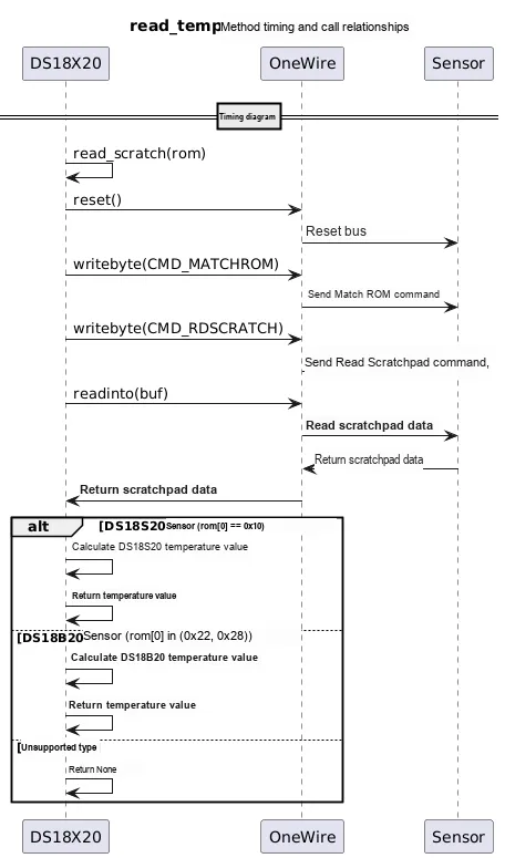
We also defined the resolution () method for setting and reading the temperature conversion resolution, which mainly implements the setting of the temperature conversion resolution by writing the updated configuration data into the sensor's scratchpad register:
def resolution(self, rom: bytearray, bits: int = None) -> int:
    """
    Set or read the sensor temperature conversion resolution.

    Args:
        rom (bytearray): ROM address of the target temperature sensor.
        bits (int): Temperature conversion resolution (9~12 bits). If None, read the current resolution.

    Returns:
        int: The resolution in bits that was set or read.
    """
    if bits is not None and 9 <= bits <= 12:
        # Set the resolution information to the value of the bits variable
        # Bit 3 of self.config is used to set the resolution
        self.config[2] = ((bits - 9) << 5) | 0x1f
        self.write_scratch(rom, self.config)
        return bits
    else:
        data = self.read_scratch(rom)
        return ((data[4] >> 5) & 0x03) + 9
The specific process is shown in the following figure:
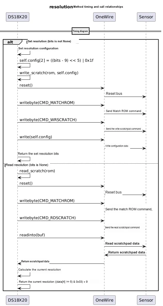
It should be noted that the higher the resolution, the higher the accuracy of the temperature value, but the corresponding conversion time will also be longer. By adjusting the resolution, a trade-off can be made between accuracy and conversion speed to meet the needs of different application scenarios.
For DS18 series sensors, the conversion accuracy and time are as follows:
Conversion Accuracy / Bit | Conversion time/ms |
9 | 94 |
10 | 188 |
11 | 375 |
12 | 750 |
Finally, we have defined conversion methods for Celsius, Kelvin, and Fahrenheit. Among them, Celsius is the most widely used temperature unit, applicable to most daily life and industrial application scenarios. Fahrenheit is mainly limited to North America, while Kelvin is primarily used for scientific research and some high-precision industrial applications. The relationship among the three is as follows:
- The conversion formula between Kelvin and Celsius is: K = °C + 273.15
- The conversion formula between Fahrenheit and Celsius is:°F = °C × 1.8 + 32
def fahrenheit(self, celsius: float) -> float:
    """
    Convert degrees Celsius to degrees Fahrenheit.

    Args:
        celsius (float): Degrees Celsius.

    Returns:
        float: Degrees Fahrenheit. If the input is None, returns None.
    """
    return celsius * 1.8 + 32 if celsius is not None else None

def kelvin(self, celsius: float) -> float:
    """
    Convert degrees Celsius to kelvins.

    Args:
        celsius (float): Degrees Celsius.

    Returns:
        float: Kelvins. If the input is None, returns None.
    """
    return celsius + 273.15 if celsius is not None else None
3.2.3 Application Experiment
In the following experiment, we need to insert the Fengya No. 1 Board - Grove Interface expansion board into the Fengya No. 1 Board - Universal Compatible Expansion Board, and meanwhile use a HY2.0-4P cable to connect the DIO0 interface on the Fengya No. 1 Board - Universal Compatible Expansion Board and the DIO0 digital interface on the GraftSense - DS18B20-based temperature sensor module:
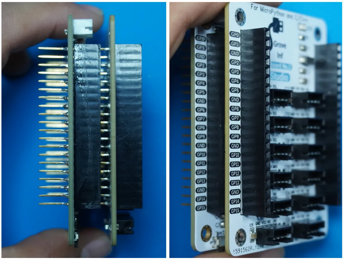
The pins used are shown in the following table:
Pico pins | MY18E20 Pin |
GPIO14 | DATA |
VBUS | VCC |
GND | GND |
The following code can be found in the material package we provide, under the elegance-devkit v1\Demo\38 OneWire_DS18B20 folder.
In the software code, we import the relevant modules:
# Python env   : MicroPython v1.23.0
# -*- coding: utf-8 -*-
# @Time    : 2024/7/22 3:01 PM
# @Author  : Li Qingshui
# @File    : main.py
# @Description : DS18B20 temperature experiment, using single-bus communication for data exchange

# ======================================== Import Modules ========================================

# Import hardware-related modules
from machine import Pin
# Import time-related modules
import time
# Import modules for single-bus communication
from onewire import OneWire
# Import the temperature sensor class
from ds18x20 import DS18X20
In the initialization configuration, we define the one-wire communication pin ow_pin, and meanwhile create a DS18X20 object and bind it to ow_pin for communicating with the DS18B20 sensor:
# ======================================== Global Variables ============================================

# ======================================== Functions ============================================

# ======================================== Custom Classes ============================================

# ======================================== Initialization ==========================================

# Delay to wait for the device to initialize
time.sleep(3)
# Print debug information
print('FreakStudio : Using OneWire to read DS18B20 temperature')

# Define the single-bus communication pin
ow_pin = OneWire(Pin(14))
# Define the temperature sensor
ds18x20 = DS18X20(ow_pin)
In the main program, we perform the following operations: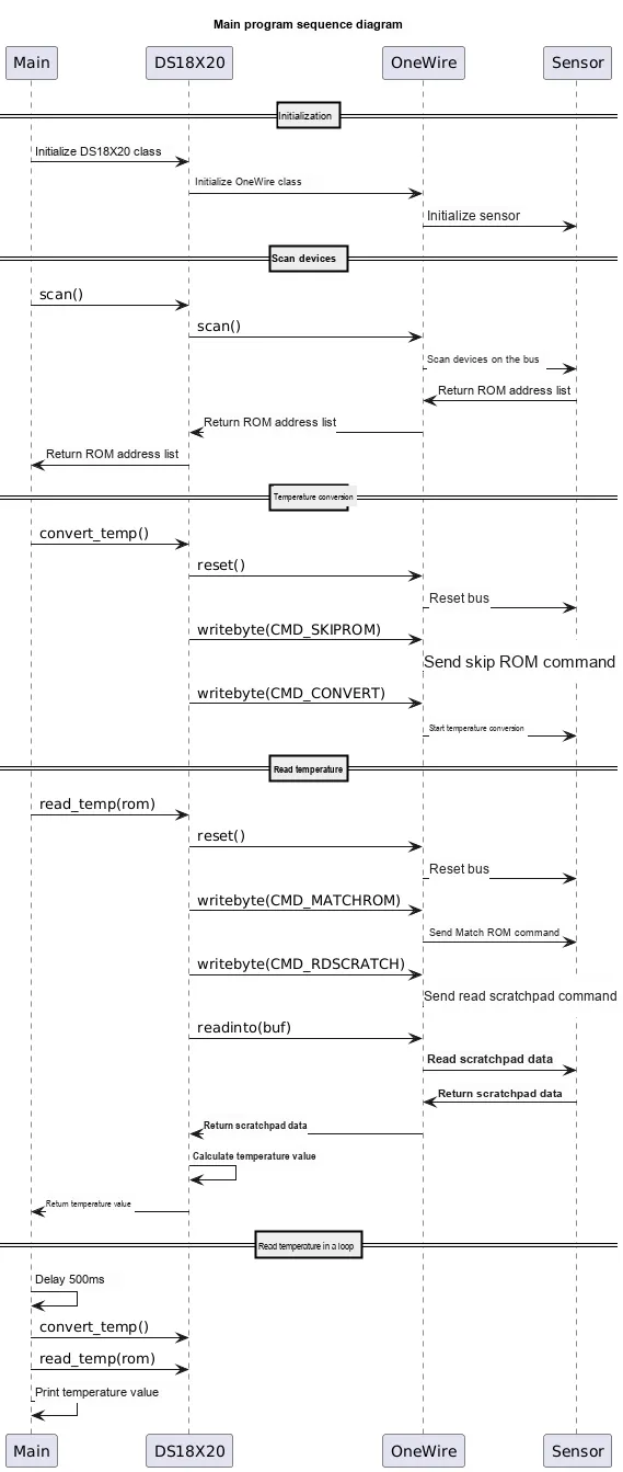
- Preparations:
- Delay for 3 seconds to ensure system stability;
- Scan the DS18B20 sensor devices on the bus to obtain the device address list
roms_list; - Print the ROM ID of the DS18B20 sensor device;
- Trigger all DS18B20 sensors to start temperature conversion;
- Temperature reading loop:
- The temperature is read once every 500 ms;
- Iterate through each device address in roms_list;
- Read the temperature value of the corresponding device and print it out;
- Trigger all DS18B20 sensors to initiate temperature conversion again;
The sample code is as follows:
# ========================================  Main Program  ===========================================

# Scan for DS18B20 devices on the bus and get the list of device addresses
roms_list = ds18x20.scan()
# Print the list of device addresses
for rom in roms_list:
    print('ds18b20 sensor devices rom id:', rom)
# Have all DS18B20 devices on the bus convert the temperature
ds18x20.convert_temp()

# Read the temperature in a loop
while True:
    time.sleep_ms(500)
    for rom in roms_list:
        # Convert and print the temperature
        temp = ds18x20.read_temp(rom)
        # Print the temperature
        print('ds18b20 sensor {} devices temp {}'.format(rom, temp))
    # Start the temperature conversion
    ds18x20.convert_temp()
Burn the code, connect to the terminal, and gently pinch the sensor with your hand; you will see the following output in the terminal:
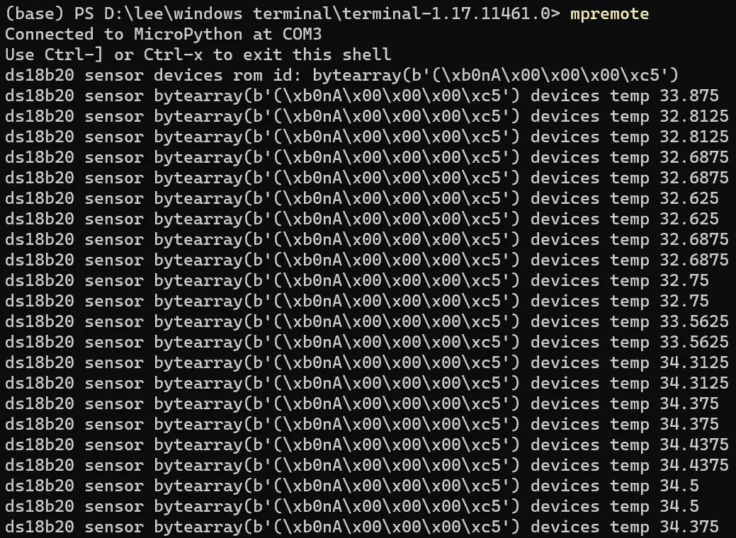
3.2 Application Experiment.mp4 41.8 MB
References
- 01Studio One-Wire Communication
https://github.com/01studiolab/MicroPython_Examples/blob/master/pyPico/2.%E4%BC%A0%E6%84%9F%E5%99%A8%E5%AE%9E%E9%AA%8C/1.%E6%B8%A9%E5%BA%A6%E4%BC%A0%E6%84%9F%E5%99%A8DS18B20/ds18x20.py
- Bus Communication - 2.3.1 1-Wire Bus Communication
https://www.cnblogs.com/deliweier-wangshuping/p/16167870.html
- How to quickly understand 1-Wire bus communication?
https://www.eet-china.com/mp/a149567.html
- MicroChip 1-Wire Application Manual
https://onlinedocs.microchip.com/pr
- 【Communication Protocol】Detailed Explanation of 1-Wire Protocol — Taking DHT11 as an Example
https://blog.csdn.net/qq_53918631/article/details/124957478
- Communication Protocol - Single Bus
https://blog.csdn.net/m0_38112603/article/details/107351915
- 1-Wire Bus Technology and Its Applications
https://www.cnblogs.com/limanjihe/p/10329959.html
- OneWire Protocol
https://python.quectel.com/doc/Application_guide/zh/hardware/peripheral-interfaces
- 1-Wire Protocol
https://docs.arduino.cc/learn/communication/one-wire/
- 1-Wire
https://en.wikipedia.org/wiki/1-Wire
- Overview of 1-Wire Technology and Its Use
https://www.analog.com/en/resources/technical-articles/guide-to-1wire-communication.html
- 1-Wire® (Protocol) Company: Dallas Semiconductor/Maxim
- Implementing 1-Wire Bus Master Using UART
https://www.elecfans.com/d/2045545.html
- [MCU Practical Experience] Implementing One-Wire Bus via UART+ DMA on STM32
https://shequ.stmicroelectronics.cn/thread-581885-1-1.html
- MicroChip: Implementing Single-Bus Communication via UART
https://onlinedocs.microchip.com/pr/GUID-1618003F-992B-4E48-9411-5E5D5D952C06-en-US-3
- Using a UART to Implement a 1-Wire Bus Master
https://www.eeweb.com/using-a-uart-to-implement-a-1-wire-bus-master/
- Using DS18B20 Temperature Sensor on Raspberry Pi Pico
https://pico.nxez.com/2023/11/17/how-to-use-the-ds18b20-on-raspberry-pi-pico.html
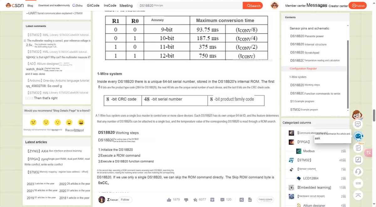
- 【Common Sensors】Detailed Explanation of DS18B20 Temperature Sensor Principle and Routine Code
https://blog.csdn.net/as480133937/article/details/112604303

- STM32F103 Driver for DS18B20 Temperature Sensor (Extremely Detailed Program Comments)
https://blog.csdn.net/qq_41151593/article/details/108418652
Version Record
Version Number | Modifier | Time | Content |
v1.0.0 | Li Zisheng | 2025/09/18 | Initialize the document, based on MicroPython version V1.23.0. |
v1.0.1 | Li Zisheng | 2025/12/05 | Initialize the document, based on MicroPython version V1.23.0. Some images have been added. |
v1.1.0 | Li Zisheng | 2025/12/15 | All images have been modified successfully. |