
Contents
- 0. What Is This?
- 0.1 What is this?
- 0.2 Object Oriented
- 0.3 Why Choose MicroPython + Fengya No. 1 Board
- I. Introduction to Fengya No. 1 Board and Shipping Accessories
- 1.1 Universal Compatible Expansion Board
- 1.2 Colorful Touch Expansion Board
- 1.3 Environmental and Storage Acquisition Board
- 1.4 OLED Display and Interaction Expansion Board
- 1.5 LCD Screen Human-Machine Interaction Board
- 1.6 Serial Port Level Conversion Board
- 1.7 Data Conversion Board
- 1.8 Adjustable DDS Signal Generation Board
- 1.9 Grove Base Shield
- 1.10 Ethernet and SD Card Expansion Board
- II. What will you learn?
- 2.1 Core Information Summary of Raspberry Pi Pico & RP2040
- 2.2 Brief Introduction to MicroPython Language
- 2.3 Setting Up the MicroPython Development Environment
- 2.4 Using the REPL Interactive Interpreter
- 2.5 Basic Principles of Microcontroller Peripherals and Introduction to Corresponding Registers of Raspberry Pi Pico
- 2.6 Relevant Methods for MicroPython to Control Corresponding Peripherals and Usage of Related Tool Software
- 2.7 Related Application Experiments
- 2.8 Communication Protocol and Component Library Section
- III. What teaching materials are available?
- 3.1 MicroPython Teaching Knowledge Base
- 3.2 Quick Start Guide for Scalable Electronic Modules and Hardware Principles
- 3.3 Rapid Prototype Expansion Board and Teaching Case Library
- 3.4 Advanced Python Programming Tutorial
- 3.5 Full Open Source for Cases and Hardware
- 3.6 Dedicated uPyPI Platform
- 3.x Bipes-based MicroPython Graphical Tutorial - DIY for Primary and Secondary School Students / Zero Beginners
- IV. What after-sales services are available?
- 5. Relevant web addresses and open-source code repositories
- References
- Knowledge Base Version Record
Welcome to the Wiki of the tutorial *Getting Started with MicroPython: Playing with the Raspberry Pi Pico Microcontroller*!
This is a Raspberry Pi Pico microcontroller tutorial ranging from "zero-based beginner" to "comprehensive practical combat" — we use MicroPython as the development language to help you skip the complicated underlying compile, directly focus on "hardware interaction + function implementation", and get started with this lightweight and flexible microcontroller with ease.
0. What Is This?
0.1 What is this?
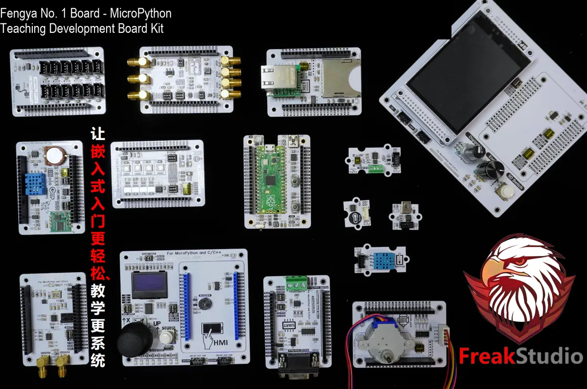
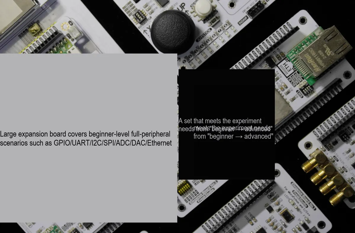
A stacked open-source development board kit designed exclusively for MicroPython teaching, making embedded system learning easier and teaching more systematic!!!
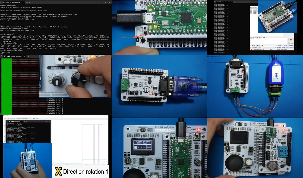
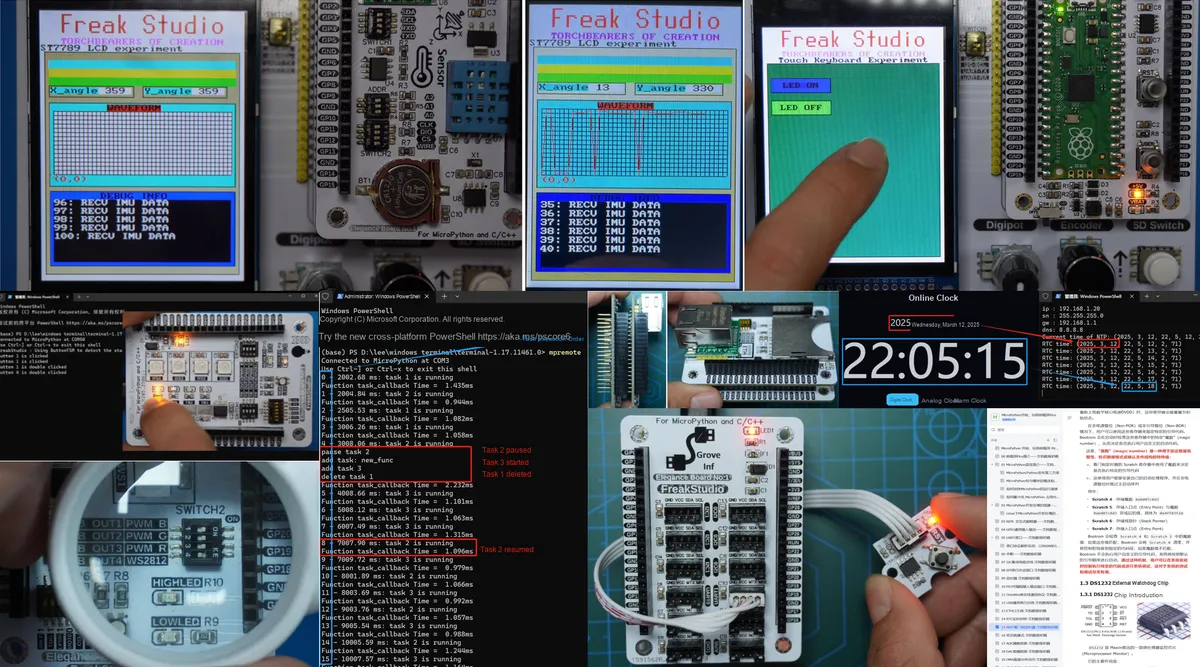
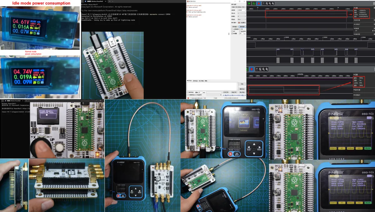
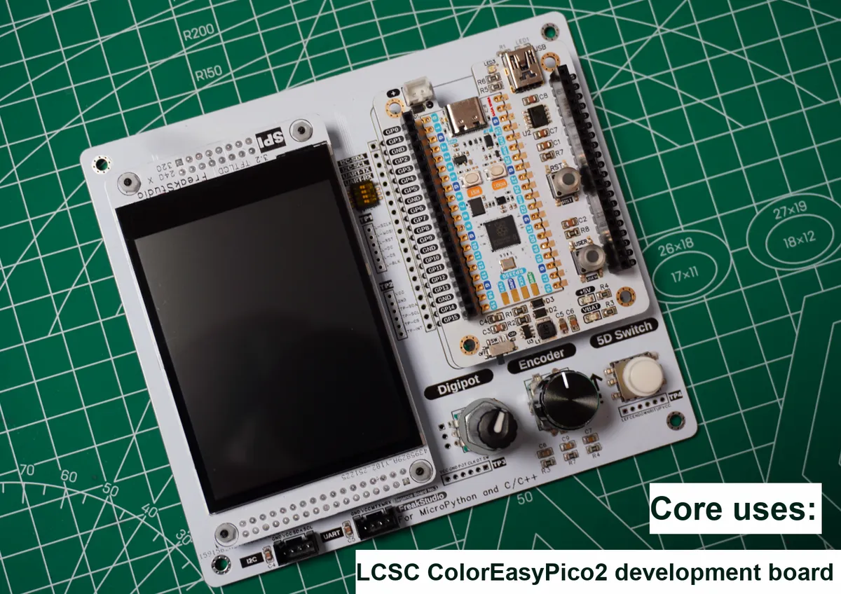
- ✨ Low barrier to entry: Say goodbye to the discouraging embedded learning experience: Ditch the pain points of traditional embedded development such as "slow compile, environment setup, and tedious register study", and leverage the no-compile feature of MicroPython to get instant code modification effects and real-time feedback from REPL interactive debugging;even total beginners can light up an LED and read sensor data in 10 minutes, with zero delay from "writing code" to "seeing results", you can quickly gain a sense of achievement without wasting half a day on low-level configuration ever again.
- 🛠️ Full-scenario Practical Training: Precision Adaptation of hardware + Content in Teaching
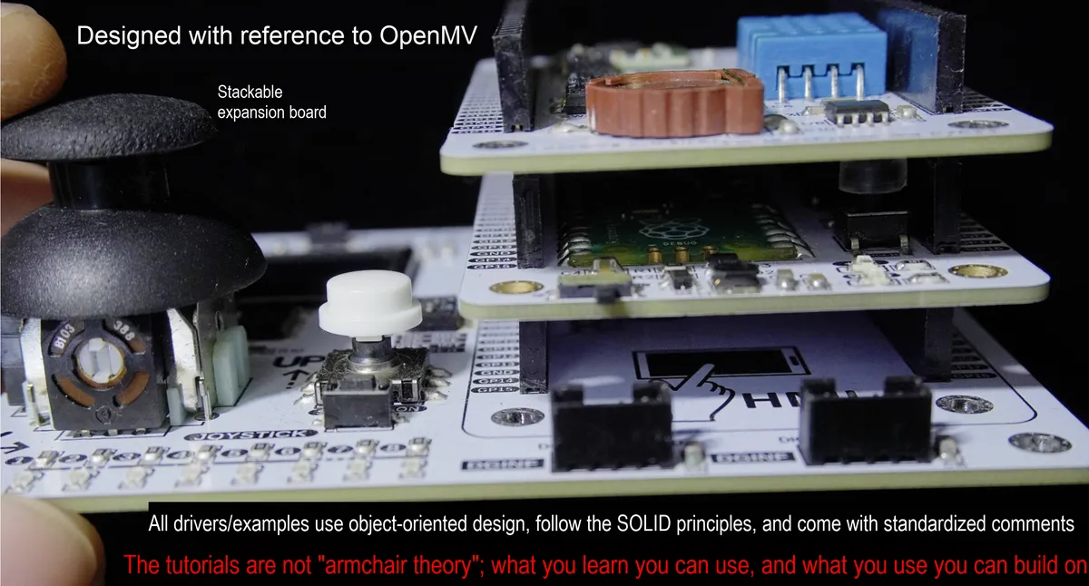
- Hardware side: A stacked expansion board designed with reference to OpenMV. Its 10 types of expansion boards cover all peripheral scenarios including GPIO, UART, I2C, SPI, ADC, DAC, Ethernet, etc. It is compatible with the full range of Raspberry Pi Pico core boards, and one set meets all experimental requirements from beginner to advanced level;
- Content Module: The tutorials avoid empty theorizing; every knowledge point corresponds to a combination of "hardware hands-on practice + code examples + project implementation", covering everything from button interaction, temperature and humidity collection to waveform generators and MQTT IoT nodes — you master every topic you learn, and deliver every project you build.
- 🎯 Standard Code: Align with standard development practices right from the beginner level
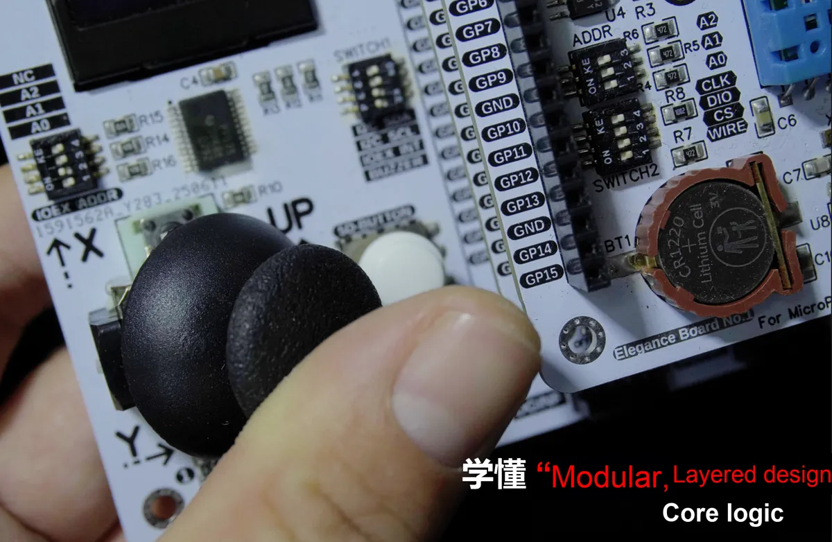
- At the code level: all drivers/cases are designed with Object Oriented principles, follow the SOLID principles, and come with standardized comments — they not only run properly, but also help users grasp the core logic of "Modularization and layered design";
- Hardware level: Fully open-source design files adapted for manual soldering (core resistors and capacitors in 0805 package), guiding users from "using hardware" to "making hardware" to cultivate a complete mindset of electronic engineering.
- 🔧 Open-source and Extensible: Turning "Learning Tools" into "Creation Platforms"
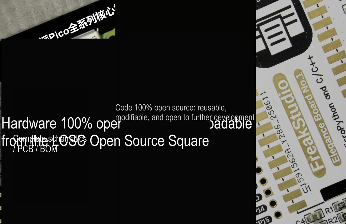
- 100% open-source code: reusable, modifiable, and suitable for secondary development; it supports publishing your own libraries to the dedicated uPyPI platform to build a personalized embedded toolchain.
- 100% open-source hardware: You can download the complete set of schematics, PCB and BOM on LCKFS Open Source Square. Beginners can replicate it, while experienced users can DIY it. It supports everything from "learning from existing designs" to "creating exclusive custom solutions", with unlimited room for tinkering.
- 📈 Closed-loop Learning: From "Grasping Knowledge Points" to "Delivering Finished Products"
- Build a complete learning closed loop of "principle decomposition → code practice → prototype production → iterative optimization":
- Foundation Phase: Master the MicroPython syntax and the principles of hardware peripherals thoroughly;
- Advanced phase: Use the rapid prototyping expansion board to complete practical projects such as IoT monitoring and interactive devices;
- Advanced Phase: Through open-source code / hardware modification, upgrade the work into a demo-ready product-level prototype, and truly realize the concept of "learn to apply immediately, apply to create freely".
- 🎨 Layered Teaching: Tailored Learning Paths for Different Groups
- Zero-based / Teenagers: Bipes graphical programming uses drag-and-drop blocks to control hardware. Even those with zero coding foundation can create interactive inventions, and can easily transition to professional development through the "graphics → code" comparison;
- College students / developers: Supporting advanced tutorials including Object Oriented Programming and Parallel Computing, it combines embedded scenarios to cultivate engineering thinking, helping quickly implement course projects / product prototypes;
- MicroPython enthusiasts: Supplement underlying principles + Performance optimization tips, advance from "being able to use" to "mastering", and fill the gaps in core embedded capabilities.
- 🚀 Exclusive ecosystem support: Say goodbye to the hassle of "scrambling for resources and falling into frequent pitfalls"
- Self-developed uPyPI package management platform, plus supporting Wiki, graphic and video tutorials for over 100 sensors, enables one-click installation of driver libraries and instant access to reference materials, along with a dedicated community for Q&A — no need to search scattered tutorials across the web, this single set of resources covers the entire end-to-end MicroPython embedded development process.
0.2 Object Oriented
| Target Audience | Description |
|---|---|
| Absolute beginners and hobbyists | People who want to build electronic gadgets but do not know complex technology. |
| Computer science university students | People who want to quickly turn hardware product prototypes into reality, or get started with embedded development. |
| MicroPython enthusiasts | Fill in gaps in fundamentals and improve engineering skills. |
0.3 Why Choose MicroPython + Fengya No. 1 Board
0.3.1 Why MicroPython (mpy)
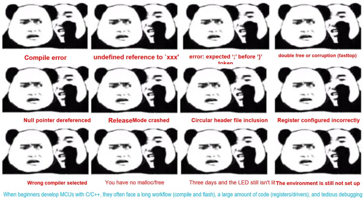
Reasons why traditional embedded development is prone to being abandoned:
- Slow compile: Modifying the code requires re-compiling and re-downloading, which wastes time.
- Lack of a sense of achievement: There are numerous issues with environment configuration and drivers, making it impossible to produce tangible results even after half a day of work.
- Difficult syntax: C language pointers and register configurations are hard for beginners to understand.
- Trap for Beginners: Spending excessive time learning about clocks and pin configurations, which prevents rapid application development.
- Advantages of MicroPython:
- No need to compile: The code runs directly, and modifications take effect immediately.
- Real-time debugging: The terminal allows direct viewing of sensor data and test commands, eliminating the need for repeated firmware flashing.
- Easy to operate: No need to deal with underlying registers, you can control the hardware by calling the existing functions.
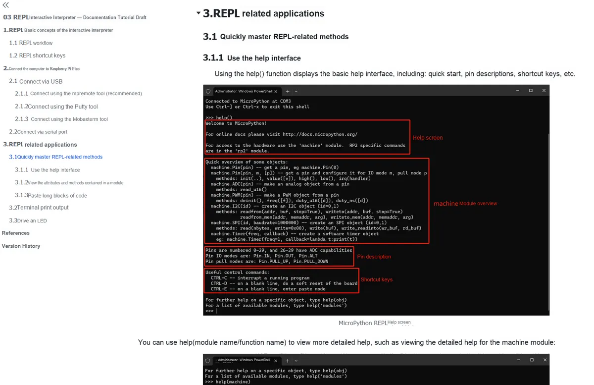
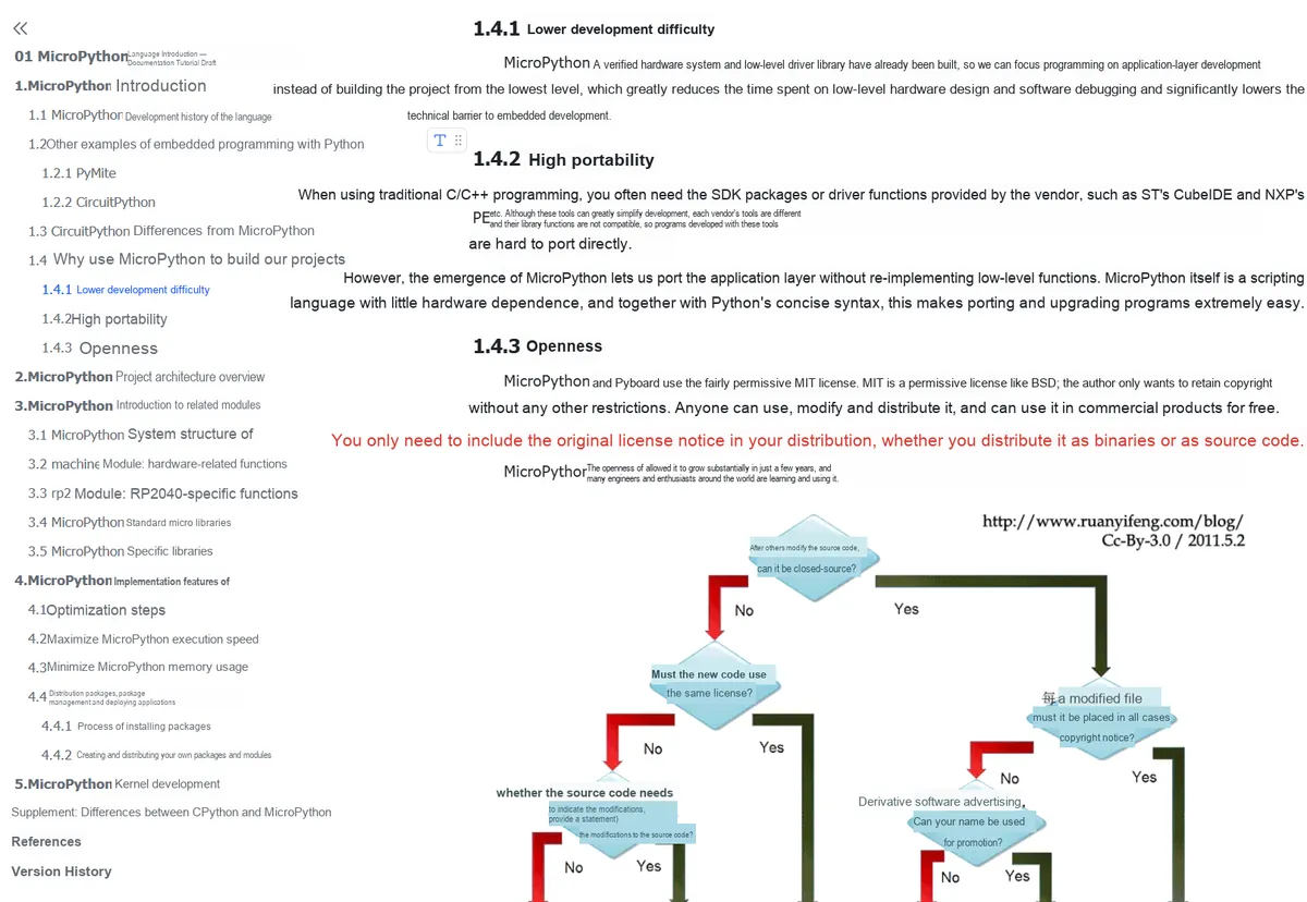
- There is no need to worry about the speed:
- Most modules are sufficient: the sensor communication speed is limited, and MPY can keep up.
- There is a solution for high-speed requirements: use PIO or DMA technology to improve performance.
- Optimizable: The code can be compiled into. mpy files, with a speed close to that of C language.
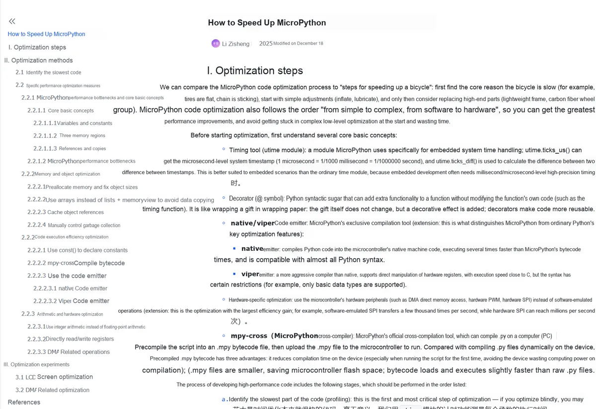
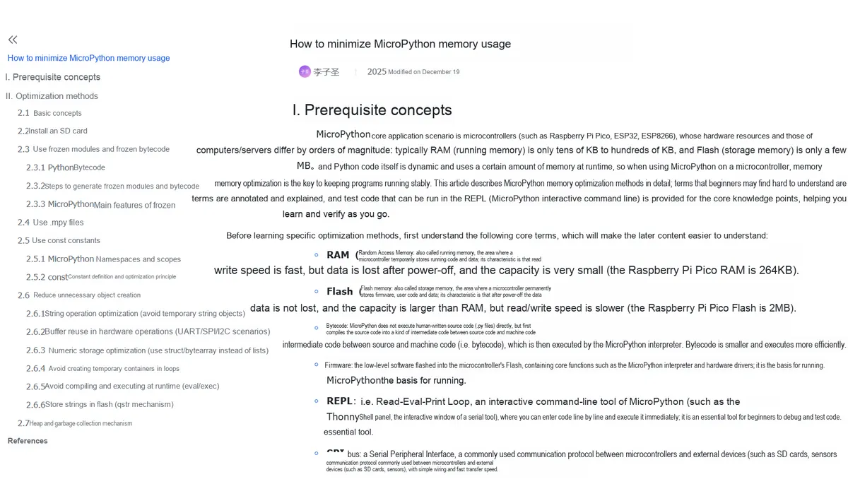
- Getting started won't disrupt your work:
- Quickly grasp the core logic: build an interaction framework between hardware and software, and maintain learning interest.
- Alignment of work priorities: Focus more on business logic in practical work rather than underlying drivers.
- Understand development frameworks: learn Modularization and layered design to adapt to work requirements.
- You can also learn the underlying knowledge if you want to: the supporting tutorials, combined with the chip manual, explain the underlying principles and driver development.
0.3.2 Why Choose Elegance No. 1 Board / Choose Us
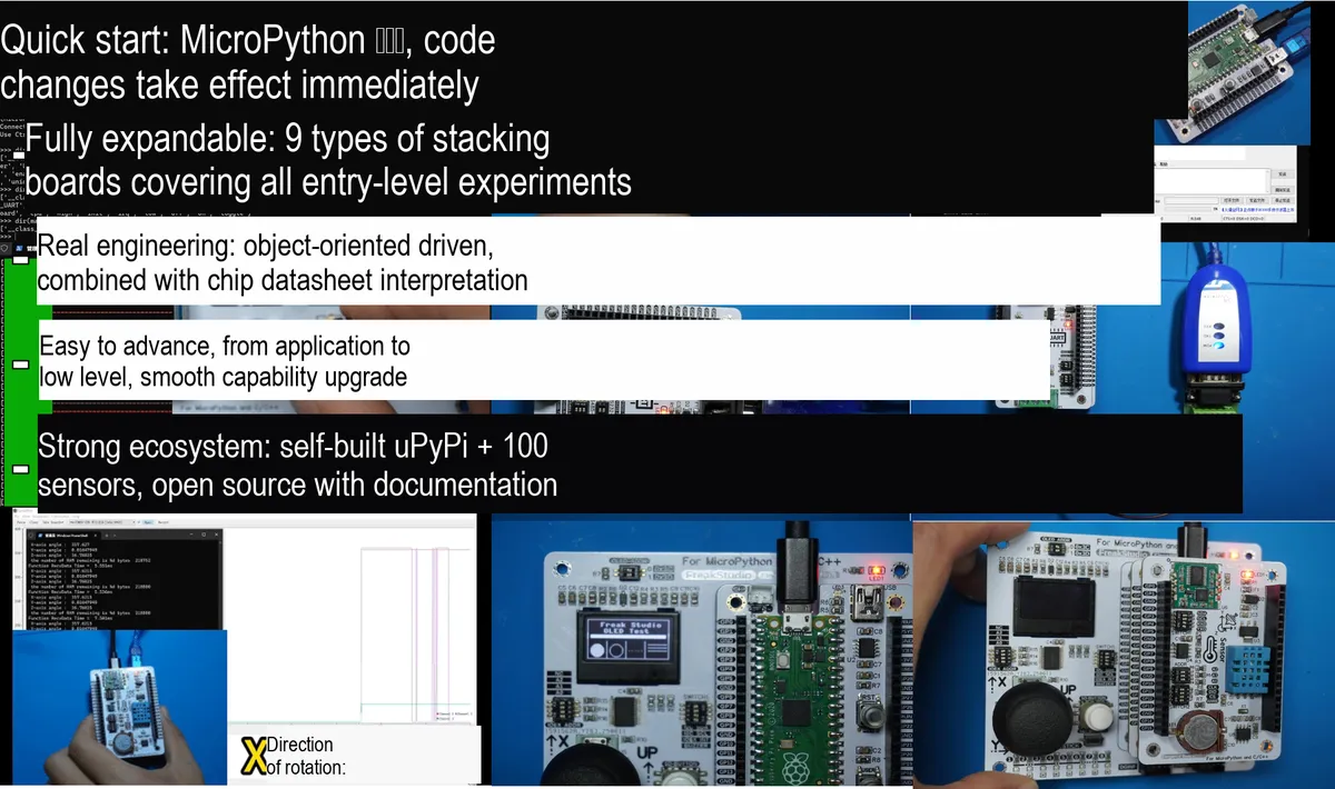
Why Choose Us?
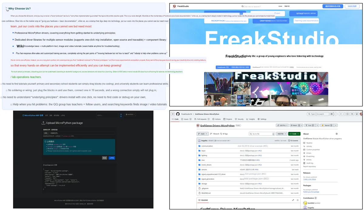
When you choose the Fengya No. 1 board, what you get is never just a set of "bare hardware", but a "worry-free implementation guarantee" that runs through the entire creative cycle — this is our core confidence. Most kits on the market only stay at the level of "providing hardware plus basic documentation", but as a tech-focused startup team, we invest our costs squarely in the areas that you don't see but have the most inelastic demand for:
- Professional MicroPython driver, covering everything from getting started to underlying principles;
- Exclusive driver libraries for multiple sensor modules (supporting one-click MIP installation, open-source and traceable) + component libraries;
- Wiki Knowledge Base + cross-platform text, image and video tutorials (for troubleshooting via on-demand search);
- We also provide after-sales support with fast response and customized training services, which thoroughly addresses the pain points of "knowing hardware but not knowing how to teach" and "having no one to turn to when problems arise".
We do not engage in one-off sales; instead, we are your long-term partner that accompanies you all the way from "scattered modules" to "finished prototypes", and from basic experiments to competition projects. Every penny you spend saves time for your ideas, detours, and ensures that every hands-on effort can be efficiently implemented and drive continuous growth!
For bulk purchases by schools, teaching plans can be customized based on students' foundation, curriculum arrangement and class hour planning; orders of 500 sets or above come with 36 class hours of training for science and technology teachers/laboratory operation teachers.
✅ No need to find tutorials on your own: primary and secondary school students can just drag and drop blocks (no coding required), while college students can learn professional skills;
✅ No wiring by soldering: Simply plug in the module for immediate use, one connection can be completed in 10 seconds, and it cannot be plugged in if the connection is wrong;
✅ No need to understand "underlying principles": one-click driver installation, no need to find codes or debug manually;
✅ Get help when in trouble: There are teachers and fellow patients in the QQ group, and you can find picture/video tutorials by searching for keywords
I. Introduction to Fengya No. 1 Board and Shipping Accessories
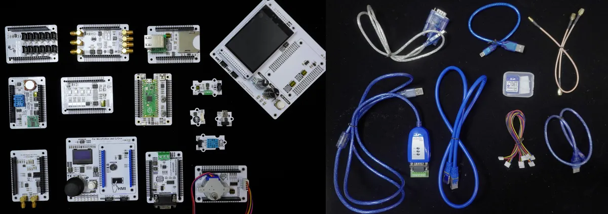
The packing list includes the following items:
Name | Specifications/Accessories | Quantity |
Universal Compatibility Expansion Board | It is equipped with a Raspberry Pi Pico core board, along with an onboard CH340K USB-to-TTL chip, a reset button and a user button. | x1 |
7-inch Color Touch Expansion Board | It comes with one TTP224, four WS2812, one RGB LED, and a pair of LEDs triggered by high and low levels respectively. | x1 |
Environmental and Storage Expansion Board | On-board components include a serial gyroscope, DHT11, DS1302 RTC chip, and AT24C256. | x1 |
OLED Display and Interaction Expansion Board | It is equipped with an onboard 0.96-inch OLED screen, a 16-bit IO expansion chip, a 5-way navigation key, an independent SET key, an analog joystick, a passive buzzer, 8 LEDs and two Grove digital interfaces. | x1 |
LCD Screen Human-Machine Interaction Expansion Board | It is equipped with a 3.2-inch on-board LCD touch screen, a rotary potentiometer, a 5-way navigation key, a rotary encoder, as well as one UART and one I2C Grove interface. | x1 |
Serial Port Level Conversion Board | It is equipped with one MAX13487 chip and one MAX3232 chip onboard. | x1 |
Data Conversion Board | This board is not equipped with an onboard ADS1115, an onboard MCP4725, nor two SMA interfaces for internal ADC inputs. | x1 |
Adjustable DDS Signal Generation Board | Onboard AD9833 and MCP41010 chips, with two SMA interfaces. | x1 |
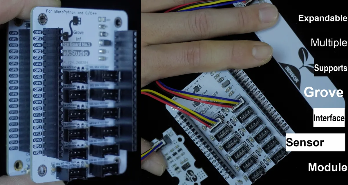
Grove Interface Expansion Board | Multiple HY2.0-4P interfaces compliant with the Grove specification are integrated on the board. | x1 |
Ethernet and SD Card Expansion Board | Onboard W5500 module and SD card. | x1 |
GraftSense: A USB-to-TTL Module Based on CH340K | HY2.0-4P-Reverse Cable x 1, MiniUSB Cable x 1 | x1 |
GraftSense - A Temperature Sensor Module Based on DS18B20 | HY2.0-4P-Reverse Flat Cable x 1 | x1 |
GraftSense - A Watchdog Module Based on the DS1232 Chip | HY2.0-4P-Reverse Flat Cable x 1 | x1 |
GraftSense - Digital Potentiometer Module Based on DS3502 | HY2.0-4P-Reverse Cable x 1 MCX Male to Red-Black Dupont Wire x 1 | x1 |
GraftSense - Adjustable Power Supply Module Based on LM2596S | Lithium-ion battery charger set x 1 | x1 |
USB to MicroUSB Cable | 0.5m | x1 |
MiniUSB cable x 1 | 0.25m | x1 |
Ethernet cable | 1m Category 6 Gigabit | x1 |
RS232 to USB connector | 0.5m | x1 |
RS485 to USB Connector | Industrial Grade USB to 485 Converter | x1 |
logic analyzer | NanoDLA | x1 |
SMA Male to SMA Female | x1 | |
SMA to red-black Dupont wires | x1 | |
SMA to MCX cable | x1 | |
Polymer lithium battery | x1 | |
SD card | industrial-grade | x1 |
1.1 Universal Compatible Expansion Board
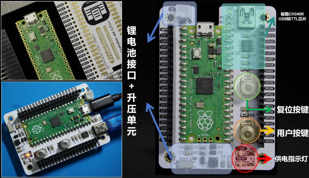
This is a flexible development adaptation platform that is compatible with soldering multiple microcontroller core boards of the Raspberry Pi Pico series through on-board pads, allowing users to flexibly select the main controller as needed; meanwhile, it integrates an on-board CH340K USB-to-TTL chip, a reset button and a user button, providing functions for program burning, serial port debugging and customization. With the design concept of "one platform, multiple cores", it transforms fixed hardware into a customizable development system, supports Out Of The Box, and can serve as the foundation of various projects to carry the core board and connect to a computer for programming and debugging.
Raspberry Pi Pico Pin Numbering | Corresponds to the MCU peripheral | Extension Board Corresponding Device |
GP0 | UART0-TX | USB to TTL Chip - RXD |
GP1 | UART0-RX | USB to TTL Chip - TXD |
RUN | Digital IO | RST Button - Digital Signal Output |
GP22 | Digital IO | USER Button - Digital Signal Output |
1.2 Colorful Touch Expansion Board
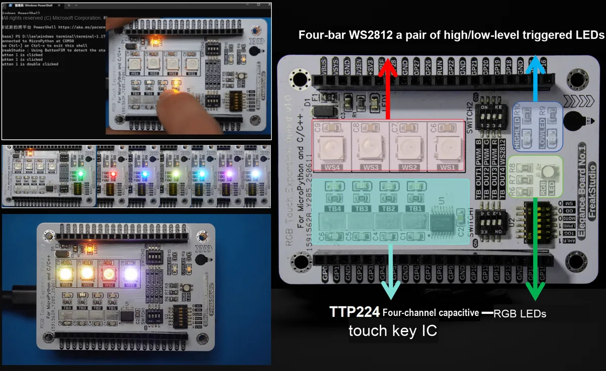
- Core Functions: Deliver modern touch interaction and stunning RGB lighting effects.
- Component Details:
- TTP224: 4-channel capacitive touch key IC.
- WS2812: Four circular LED strips, with each LED capable of being independently programmed to control its color and brightness.
- RGB LED: A full-color LED light.
- High/Low Level Triggered LED: Basic status indicator.
- Design Concept: Combine stunning lighting effects with touch control to create an engaging interactive experience.
Raspberry Pi Pico Pinout | Corresponding MCU peripherals | Expansion board compatible devices |
GP10 | Digital IO | Touch Key 1 - Digital Output |
GP11 | Digital IO | No. 2 Touch Key - Digital Output |
GP12 | Digital IO | Touch Key No. 3 - Digital Output |
GP13 | Digital IO | Touch Key 4 - Digital Output |
GP21 | PWM Timer | RGB LED Light - BLUE Terminal |
GP20 | PWM Timer | RGB LED Light - GREEN Terminal |
GP19 | PWM Timer | RGB LED Light - RED Terminal |
GP18 | Digital IO | WS2812 - Signal Input Terminal |
GP17 | Digital IO | Common Anode LED - High Level |
GP16 | Digital IO | Common Cathode LED - High Level |
1.3 Environmental and Storage Acquisition Board
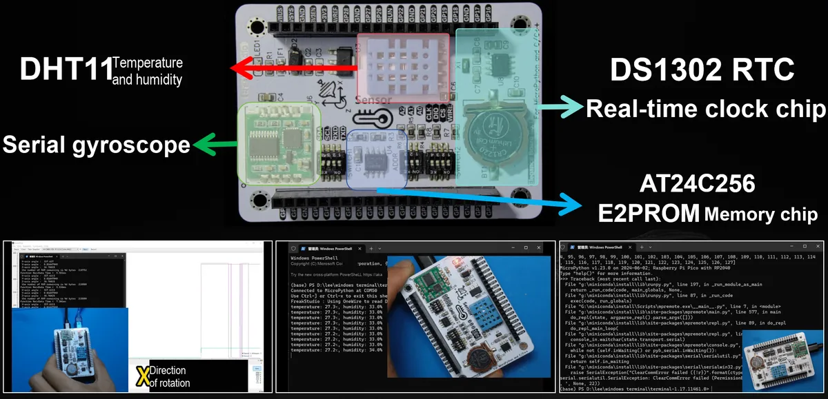
- Core Functions: Integrates a variety of commonly used sensors and storage modules for Data Acquisition and recording.
- Component Details:
- Serial Port Gyroscope: Outputs data via UART, measures angular velocity, and senses the attitude of objects.
- DHT11: Collects ambient temperature and humidity data.
- DS1302 RTC: Equipped with a backup battery, it delivers precise real-time clock functionality and keeps running without interruption even when powered off.
- AT24C256: An EEPROM memory chip with I2C interface (256 Kbit), used for storing system configurations or collected data.
- Design Concept: It provides an all-in-one solution to meet the requirements of monitoring environmental parameters, motion status and time, as well as non-volatile data storage.
- Typical Applications: environmental monitoring stations, data loggers, time-triggered automated devices.
Raspberry Pi Pico Pinout | Corresponding to MCU peripherals | Expansion Board Corresponding Device |
GP2 | I2C1-SDA | EEPROM chip AT24C256-I2C-SDA |
GP3 | I2C1-SCL | EEPROM chip AT24C256-I2C-SCL |
GP4 | UART1-TX | Serial Port Gyroscope - UART - RX |
GP5 | UART1-RX | Serial Port Gyroscope - UART - TX |
GP10 | Digital IO | RTC real-time clock chip DS1302-CLK |
GP11 | Digital IO | RTC Real-time Clock Chip DS1302-DIO |
GP12 | Digital IO | RTC Real-Time Clock Chip DS1302-CS |
GP13 | Digital IO | DHT11 Temperature and Humidity Chip - 1-Wire Bus |
1.4 OLED Display and Interaction Expansion Board
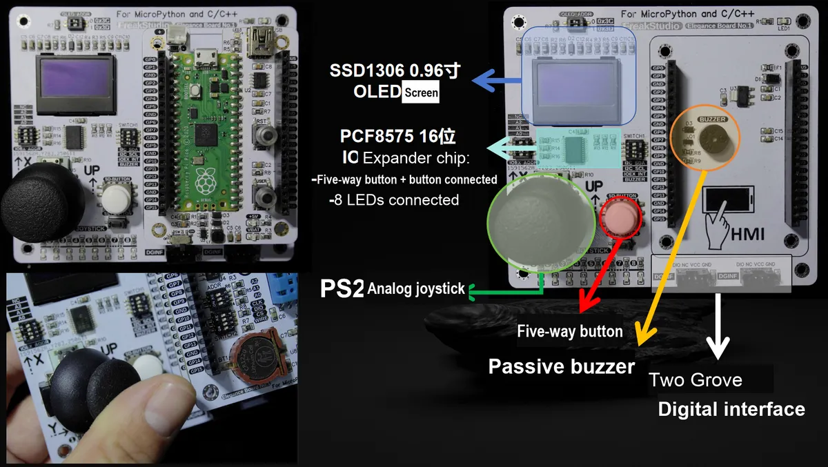
- Core Functions: Deliver display and diverse interactive capabilities within a compact form factor.
- Component Details:
- OLED Screen: A monochromatic display with high contrast, suitable for presenting text, icons and data.
- IO Expansion Chip: Expands the main control IO and is used to manage multiple components on the board.
- Input Devices: 5-way button, independent SET button, analog joystick.
- Output Devices: Passive buzzer (for sound output), 8 LED lights (for status indication).
- Expansion Interfaces: Two Grove digital interfaces.
- Design Philosophy: The IO expansion chip optimizes the GPIO resources of the main controller.
Raspberry Pi Pico Pin Numbering | Corresponding to MCU peripherals | Expansion Board Compatible Devices |
GP6 | I2C1-SDA | OLED Display/IO Expansion Chip - I2C - SDA |
GP7 | I2C1-SCL | OLED Display / IO Expansion Chip - I2C - SCL |
GP8 | Digital IO | IO Expansion Chip - Interrupt Pin |
GP9 | PWM Timer | Buzzer - PWM Signal Input |
GP27 | ADC1 | Joystick X-direction - Analog Voltage Output |
GP26 | ADC0 | Joystick Y-axis - Analog Voltage Output |
GP22 | Digital IO | Digital signal output of joystick switch |
1.5 LCD Screen Human-Machine Interaction Board
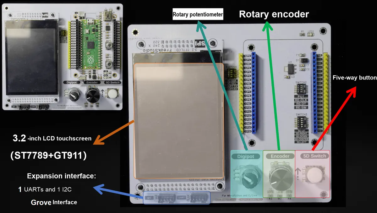
- Core Functions: Provide a complete set of graphical human-computer interaction solutions.
- Component Details:
- LCD touch screen: It provides color graphic display and touch input functions.
- Rotary potentiometer: Used for adjusting analog values (e. g., volume, brightness and contrast).
- 5-way button: provides five functions: up, down, left, right, and confirmation.
- Rotary Encoder: Provides precise digital rotary input, usually with a push-to-select function.
- Expansion Interfaces: 1 UART and 1 I2C Grove interface for connecting to other serial devices.
- Design Concept: Highly integrate commonly used interactive hardware to facilitate developers to quickly add complex User Interface and control functions to projects.
- Typical Applications: Equipment control panels, instrument interfaces, embedded system menu navigation, DIY game consoles.
Raspberry Pi Pico Pin Numbering | Corresponds to the MCU peripheral | Extension Board Corresponding Device |
GP2 | I2C1-SDA | Grove Interface - I2C - SDA |
GP3 | I2C1-SCL | Grove Interface - I2C - SCL |
GP4 | UART1-TX | Grove Interface - UART - TX |
GP5 | UART1-RX | Grove Interface - UART - RX |
GP6 | SPI0-SCK | LCD Screen - SCK |
GP7 | SPI0-MOSI | LCD Screen - MOSI |
GP8 | Digital IO | LCD Screen - RST |
GP9 | Digital IO | LCD Screen - DC |
GP10 | Digital IO | LCD Screen - CS |
GP11 | Digital IO | LCD Screen - BLK |
GP12 | I2C0-SDA | LCD Screen Touch Chip - I2C - SDA |
GP13 | I2C0-SCL | LCD Screen Touch Chip - I2C - SCL |
GP14 | Digital IO | LCD Screen Touch Chip - CS |
GP15 | Digital IO | LCD Screen Touch Chip - INT |
GP28 | ADC2 | Rotary Potentiometer - POT Voltage Output |
GP27 | Digital IO | Digital Potentiometer - CLK |
GP26 | Digital IO | Digital Potentiometer - DT |
GP21 | Digital IO | Digital Potentiometer - SW |
GP20 | Digital IO | 5-way Switch-UP |
GP19 | Digital IO | 5-way Button - RIGHT |
GP18 | Digital IO | 5-way Button - DOWN |
GP17 | Digital IO | 5-way Switch - CENTER |
GP16 | Digital IO | 5-way Button - LEFT |
1.6 Serial Port Level Conversion Board
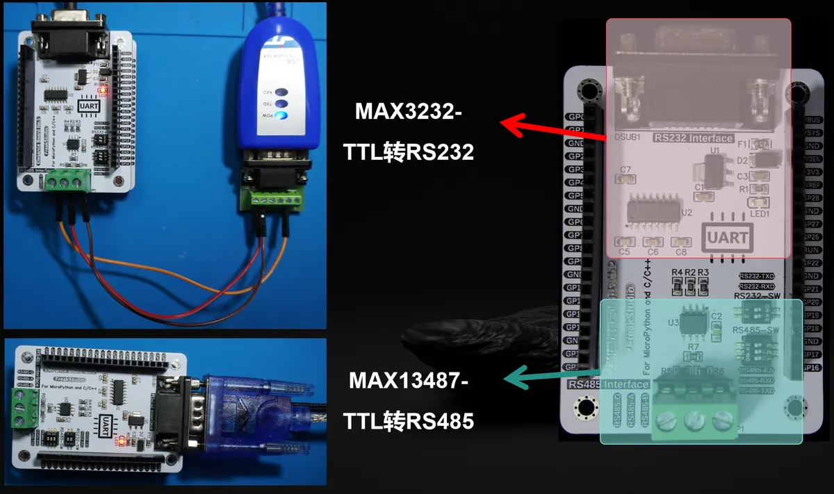
- Core Functions: Convert the TTL serial port of the motherboard into industrial/instrument standards such as RS-485 and RS-232 for easy connection with external devices.
- Chip Details:
- MAX13487: An RS-485 transceiver that supports half-duplex communication, features strong anti-interference capability, and is suitable for long-distance industrial networks.
- MAX3232: An RS-232 transceiver designed for connecting conventional devices that use ±12V logic levels, such as PCs and modems.
- Design Philosophy: To address the communication compatibility issues between embedded systems and external industrial equipment or legacy computers.
Raspberry Pi Pico Pinout | Corresponding MCU peripherals | Expansion board compatible devices |
GP18 | Digital IO | MAX13487 Chip - EN |
GP17 | UART0-RX | MAX13487 Chip/MAX3232 Chip - TX |
GP16 | UART0-TX | MAX13487 Chip/MAX3232 Chip - RX |
1.7 Data Conversion Board
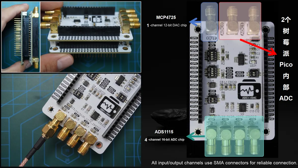
- Core Functions: Provide high-precision conversion between analog signals and digital signals.
- Chip Details:
- ADS1115: 16-bit high-precision ADC (4 channels), used to convert analog signals (such as sensor voltage) into digital values.
- MCP4725: a 12-bit DAC used to convert digital values into precise analog voltage outputs.
- Interface: All input/output channels adopt SMA interfaces, featuring reliable connection and being suitable for high-frequency signals or signals requiring interference shielding.
Raspberry Pi Pico Pinout | Corresponding to MCU peripherals | Expansion Board Corresponding Device |
GP2 | I2C1-SDA | ADS1115 Chip / MCP4725 Chip - I2C - SDA |
GP3 | I2C1-SCL | ADS1115 Chip / MCP4725 Chip - I2C - SCL |
GP4 | Digital IO | ADS1115 Chip - RDY |
GP27 | ADC1 | SMA connector |
GP26 | ADC0 | SMA connector |
1.8 Adjustable DDS Signal Generation Board
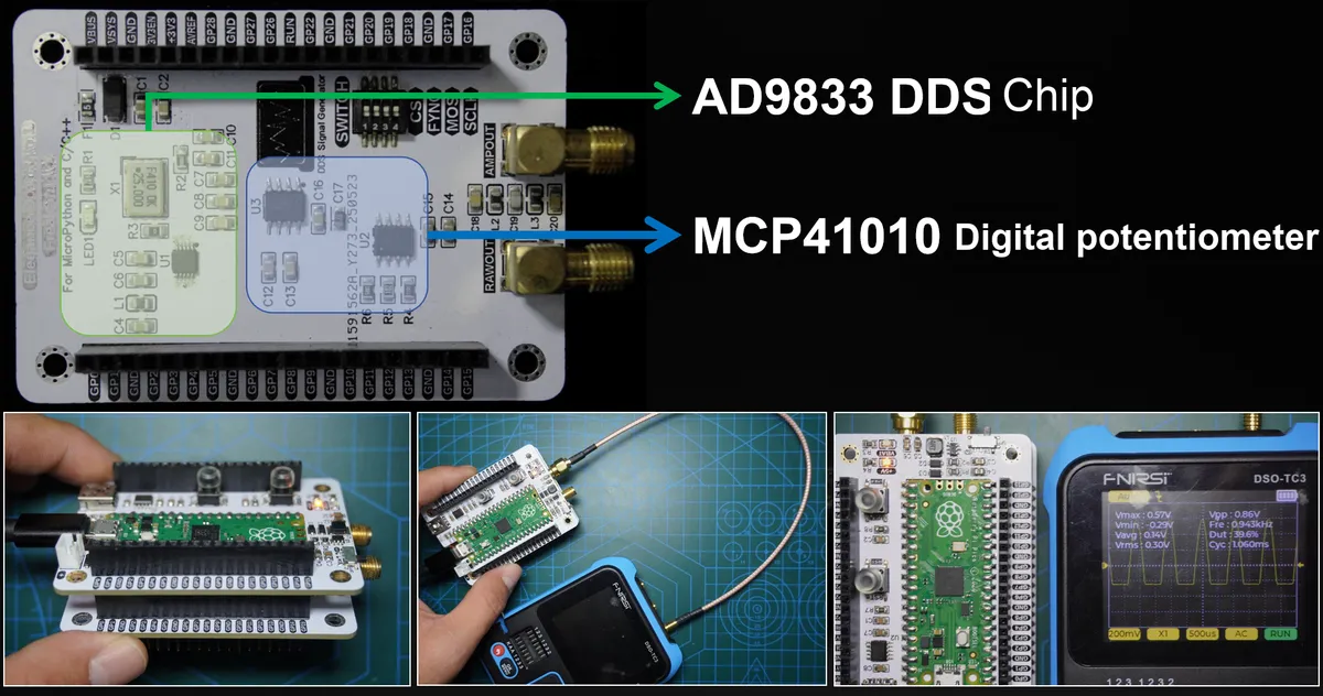
- Core Functions: Generates programmable waveforms (sine/square/triangle) with adjustable frequency and amplitude, suitable for teaching signal generation and small-scale testing.
- Chip Details:
- AD9833: A direct digital frequency synthesis chip that can generate sine waves, triangular waves and square waves, with the frequency precisely controllable via programming.
- MCP41010: A digital potentiometer, used to programmatically adjust the amplitude of the output signal.
Raspberry Pi Pico Pinout | Corresponding to MCU peripherals | Expansion Board Corresponding Device |
GP21 | Digital IO | MCP41010 Digital Potentiometer - CS |
GP20 | Digital IO | AD9833 Chip - FSYNC |
GP19 | SPI0-TX | AD9833 Chip / MCP41010 Digital Potentiometer - MOSI |
GP18 | SPI0-SCK | AD9833 Chip / MCP41010 Digital Potentiometer - SCLK |
1.9 Grove Base Shield
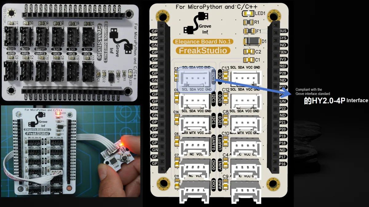
- Core Functions: It provides the capability to seamlessly connect with the Grove ecosystem. Multiple HY2.0-4P interfaces compliant with the Grove specification (typically including I2C, digital and analog interface types) are integrated on the board.
Raspberry Pi Pico Pin Numbering | Corresponding to MCU peripherals | Expansion Board Compatible Devices |
GP4 | UART1-TX | Grove-UART1 Interface - UART1-TX |
GP5 | UART1-RX | Grove-UART1 Interface - UART1-RX |
GP10 | 12C1-SDA | Grove-12C1 interface-12C1-SDA |
GP11 | I2C1-SCL | Grove-12C1 interface-I2C1-SCL |
GP12 | UART0-TX | UART0-TXGrove-UART0 Interface- |
GP13 | UART0-RX | Grove-UART0 Interface - UART0 - RX |
GP14 | Digital IO | Grove-DIO0 Interface - DIO |
GP15 | Digital IO | Grove-DIO1 Interface - DIO |
GP27 | ADC1 | Grove-AIN1 Interface - AIN |
GP26 | ADC0 | Grove-AIN0 Interface - AIN |
GP21 | I2C0-SCL | Grove-12C0 interface-I2C0-SCL |
GP20 | I2C0-SDA | Grove-12C0 interface-I2C0-SDA |
1.10 Ethernet and SD Card Expansion Board
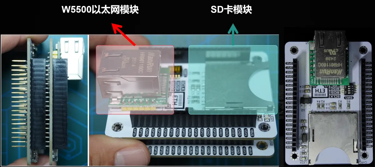
- Core Functions: It provides Ethernet network interfaces (TCP/UDP/HTTP) and local SD card storage for devices, making it ideal for remote monitoring and data logging.
- Component Details:
- W5500: A hardwired Ethernet controller with a built-in TCP/IP protocol stack, which reduces the load on the main controller and delivers stable and reliable network performance.
- SD Card Module: Reads from and writes to SD/TF cards via the SPI interface, and is used for storing large volumes of data such as images, logs and audio files.
- Design Concept: Enabling embedded devices to easily connect to local area networks/the Internet and providing them with massive data storage capacity makes this a key module for IoT projects.
- Typical Applications: network servers, IoT gateways, remote monitoring systems, data loggers
Raspberry Pi Pico Pin Numbering | Corresponding to MCU peripherals | Expansion Board Compatible Devices |
GP10 | SPI1-SCK | SD Card - SCLK |
GP11 | SPI1-TX | SD Card - MOSI |
GP12 | SPI1-RX | SD Card - MISO |
GP13 | SPI1-CSn | SD Card - CS |
GP21 | Digital IO | External Ethernet W5500 Chip - INT |
GP20 | Digital IO | External Ethernet W5500 Chip - RST |
GP19 | SPI0-TX | External Ethernet W5500 Chip - MOSI |
GP18 | SPI0-SCK | External Ethernet W5500 Chip - SCLK |
GP17 | SPI0-CSn | External Ethernet W5500 Chip - CS |
GP16 | SPI0-RX | External Ethernet W5500 Chip - MISO |
Note when using:
- Power off before plugging or unplugging (default).
- Align with the guide slot when inserting the board to avoid lateral torque.
- High-power boards (for LCD backlight, Ethernet, DDS amplification) should be placed close to the power supply or in the lower layers to avoid voltage drop.
- When multiple boards share a bus (I²C / SPI / UART), pay attention to the allocation of addresses, chip select (CS) and interrupt (INT). I²C pull-up resistors are usually already installed on the motherboard or the first expansion board, and duplicate pull-up resistors will interfere with the signal.
- Avoid removing the SD card during operation to prevent damage to the file system; do not remove the card while it is being written to.
II. What will you learn?
- Basic Capability Layer:
- Getting Started with Embedded Systems: Get to Know the Pico/RP2040 Development Board hardware, Understand Basic Circuit Principles, Master the Introductory Syntax of MicroPython, and Build Your Exclusive Development Environment
- Core Programming Competencies: Understand Object Oriented programming concepts and learn Modularization of code design (to make code more readable and maintainable)
- Hardware Practical Layer:
- Master All Peripherals: Learn driver development for over 18 peripherals including GPIO, UART, I2C, SPI, timers, PIO, ADC/DAC, etc. — grasp the principles and be able to implement practical operations
- Proficient in Communication Protocols: Understand the principles of protocols including UART, I2C, SPI, OneWire, USB, Ethernet, etc. , and implement data transmission between devices through hands-on practice
- Advanced Technical Breakthroughs: Mastering Practical Technologies Including DMA, Low-Power Modes, Watchdog, File System, and Storage
- Component and Concurrent Development: Be proficient in using third-party component libraries such as LVGL graphical interface, ulab scientific computing, upy-shell, ulogger logging, Modbus protocol, etc. ; master multithreading/coroutine development (enabling programs to handle multiple tasks simultaneously)
- Project Engineering Layer:
- Systems Thinking: Learn hierarchical design, drive architecture construction, and develop complete projects in a Modularization approach
- Practical Project: Complete practical project development covering from sensor Data Acquisition, to waveform generation, MQTT/HTTP network communication and other modules
- In-depth low-level exploration: Understand register principles by referring to chip manuals, and implement low-level drivers such as PIO assembly by hands-on coding
- Open Source Ecosystem Contribution:
- Master the release process of third-party libraries and the package management method of uPyPI
2.1 Core Information Summary of Raspberry Pi Pico & RP2040
| Top-Level Module | Sub-Module | Key Topics / Contents |
|---|---|---|
| I. Raspberry Pi Pico Introduction | 1. Pico Board Basic Parameters | Core parameters such as basic hardware specifications, operating voltage, clock frequency, storage capacity, and electrical characteristics of the board |
| 2. Pico Board Pinout | Pin definitions, function mapping, GPIO/ADC/PWM/I²C/SPI/UART correspondence, peripheral connection notes | |
| 3. Pico Board Hardware Circuits | - Power circuit: power input, power management design - Clock crystal circuit: system clock source configuration - BOOT mode selection circuit: boot mode switching logic - Power supply/current measurement circuit: voltage/current monitoring design - Chip peripheral circuit: auxiliary chips, interface expansion circuits - LED driver circuit: onboard LED control logic - Debug interface circuit: design of debug interfaces such as SWD - Pin expansion circuit: ways to extend pin functions - Test points: description of hardware test points | |
| II. RP2040 Chip Introduction | 1. Chip System Block Diagram | Internal module interconnect architecture of the chip, functional module partitioning (CPU, DMA, I/O, Periph, etc.) |
| 2. Pin Mapping | Correspondence between physical pins and internal peripherals, description of IO bank and pads | |
| 3. Pin Multiplexing Functions | Rules for switching a single pin among multiple peripheral functions, multiplexing priority and configuration methods | |
| 4. System Features and Structure Overview | - Bus interconnect structure: internal data transfer bus architecture - Address map: allocation of memory / peripheral address space - Processor subsystem: single-cycle IO block, interrupts, event signals, debug module - Cortex-M0+ core: core architecture, instruction set features - DMA: functions of the direct memory access controller - Memory: ROM (fixed program), SRAM (runtime memory), Flash (external storage) - BOOT sequence: hardware-controlled boot, processor-controlled boot flow - Power supply system: digital IO power, digital core power, on-chip voltage regulator, USB PHY power, ADC power, power-up/power-down sequence and supply schemes (3.3V single supply, external core supply, etc.) - Core voltage regulator: operating modes, output configuration, register description - Low-power mode regulation: control of sleep / deep sleep and other modes - Reset: chip-level reset, subsystem reset mechanisms - Power-on state machine: chip power-on initialization flow - Clock system: clock sources, dividers and configuration logic - GPIO interface and peripherals: function selection, interrupt control, Pads configuration - Sysinfo / Syscfg registers: management of system information and configuration parameters - TBMAN test manager: chip test and debug interface | |
| III. Official References | 1. Schematics and Datasheets | Key reference documents such as the Pico schematic, RP2040 Hardware Design Manual, and Raspberry Pi Pico Datasheet |
| 2. Boot Files and Source Code | pico-bootrom (boot loader), links to official SDK / firmware source code (pico-sdk, pico-extras) | |
| 3. Example Programs | Official C/C++ examples, MicroPython examples, example projects and usage instructions | |
| 4. User Manuals | User documents such as the Pico C SDK manual, MicroPython manual, frequently asked questions (FAQ), and Wiring manual | |
| 5. Firmware | MicroPython firmware for Pico W, Pico Probe firmware and their usage instructions | |
| 6. Other Files | Pico W wireless-related files, configuration files, toolchain scripts and auxiliary resources (drivers, patches, sample configurations, etc.) |
2.2 Brief Introduction to MicroPython Language
| Top-Level Module | Sub-Module | Key Topics / Contents |
|---|---|---|
| Introduction to the MicroPython Language | 1. Introduction to MicroPython | - Language development background- Other embedded Python solutions: PyMite, CircuitPython - Comparison of CircuitPython and MicroPython - Advantages of using MicroPython: lower development difficulty, high portability, strong openness |
| 2. Overview of the MicroPython Project Architecture | Overall project architecture design, core module partitioning, runtime and module loading flow | |
| 3. Introduction to MicroPython-Related Modules | - System structure of MicroPython - machine module: core interface for hardware interaction (GPIO/ADC/PWM/I2C/SPI/UART, etc.) - rp2 module: RP2040-specific features (PIO, etc.) - MicroPython standard micro-libraries (micropython-lib) - MicroPython-specific libraries (built into firmware and distributed externally) | |
| 4. Implementation Characteristics of MicroPython | - Optimization steps- Methods to maximize running speed (mpy, native/viper, mpy-cross, etc.) - Strategies to minimize memory usage (frozen, .mpy, qstr optimization, etc.) - Distribution packages, package management and deployment: process of creating/publishing distribution packages | |
| 5. MicroPython Kernel Development | Low-level kernel implementation, core mechanism principles (object model, GC, bytecode interpreter, module loading mechanism, etc.) | |
| Supplement | Comparison of core differences between CPython and MicroPython (interpreter implementation, standard library coverage, differences in memory/performance/extension mechanisms) | |
| MicroPython/Python Release | 1. Preface | Release background and goals (why release, target audience, expected outcome) |
| 2. MicroPython Third-Party Files | - Definition of a released library file- Library file organization (package structure, __init__.py, module layering) - Library file description: core code, README, open-source license, dependency notes, example files, etc. | |
| 3. Code Formatting Standards and Static Checking | - Format code with black - Perform static checking with flake8 - Run checks automatically with pre-commit hooks - Using GitHub accelerators (mirror/proxy tools) - Introduction to and use of the mpremote tool (deployment, REPL, file transfer) | |
| 4. Public Release on the PyPI Platform | - PyPI registration process - Steps to create and upload a distribution package (setup / pyproject / twine, etc.) | |
| MicroPython Concepts of Packages and Modules | 1. Introduction to the micropython-lib Library Modules | - Collection of MicroPython-specific modules - Trimming and porting of the Python standard library- Notes on common compatible/alternative modules |
| 2. Installing Packages and Modules Remotely | - Basic mip installation method and command parameters - mip installation demo (online installation on the device) | |
| 3. Installing Packages and Modules Manually | Manually download, unpack, and copy files to the device (using tools such as ampy, rshell, mpremote) | |
| 4. Cross Installation and Freezing | - Cross-compilation installation method (cross toolchain, generating .mpy) - Steps, advantages, and disadvantages of freezing modules (compiling modules into the firmware) | |
| How to Speed Up MicroPython Execution Speed | 1. Optimization Steps | Overall performance optimization process (locate → analyze → optimize → verify) |
| 2. Optimization Methods | - Identify the slowest code (benchmarking and profiling) - Specific measures: ① Basic concepts: variables/constants, memory partitions, references and copies ② MicroPython performance bottleneck analysis ③ Memory and object optimization: preallocation, fixed objects, using array/memoryview instead of list, caching references, manual GC control ④ Code execution efficiency: declaring constants with const(), .mpy/mpy-cross, native/viper compilers (code emitters) ⑤ Arithmetic and hardware optimization: using integers instead of floats, direct register operations, using DMA to accelerate data transfer | |
| 3. Optimization Experiments | - LCD screen driver optimization practice (reduce refreshes, batch writes, use buffers) - DMA-related optimization practice (zero-copy, direct peripheral writes) | |
| How to Minimize MicroPython Memory Usage | 1. Prerequisite Concepts | Basic principles of memory management (heap/stack/flash, how GC works, the qstr concept) |
| 2. Optimization Methods | - Basic principles and strategies - Data storage scheme using an SD card to expand external storage - Frozen modules and frozen bytecode: generation and usage process, advantages - Using files compiled to .mpy (mpy-cross) - Optimization using const constants and namespaces/scopes - Reducing temporary objects and string allocations: reusing strings/buffers, avoiding temporary containers in loops, the mechanism by which qstr stores strings in flash - Heap and GC optimization: adjusting heap size, explicitly triggering GC, avoiding concurrent allocation of large objects |
2.3 Setting Up the MicroPython Development Environment
| Top-Level Module | Sub-Module | Key Topics / Contents |
|---|---|---|
| Firmware Flashing | 1. Flashing MicroPython Firmware on the Raspberry Pi Pico | How to put the Raspberry Pi Pico into BOOTSEL mode, the UF2 firmware copy procedure, flashing precautions and common problems |
| 2. MicroPython Firmware Version on the Raspberry Pi Pico | How to check the firmware version, upgrade/downgrade procedure, features and compatibility notes of different versions | |
| Development Environment Setup | 1. PyCharm | - Online/offline installation of the MicroPython plugin- Main features of the MicroPython Tool plugin: code editing, device connection, file management, REPL interaction |
| 2. VS Code | (Not recommended for beginners) Setup procedure for a VS Code-based MicroPython development environment on Linux, plugin selection, and basic configuration | |
| 3. Thonny | (Recommended for learning) A lightweight IDE with built-in MicroPython support, suitable for beginners to write, flash, and debug code | |
| Online Simulation Platforms Supporting MicroPython | 1. Wokwi | A browser-based online simulation and debugging platform that supports running MicroPython code and peripheral simulation |
| 2. Unicorn | Another online MicroPython simulation tool that supports basic peripherals and logic verification | |
| Graphical Programming for MicroPython | 1. Graphical Programming Tools | Design program logic by drag and drop, enabling MicroPython application development with little or no code |
| Supplementary Resources | 1. References | Learning and reference resources such as official documentation, tutorials, example projects, and community articles |
| 2. Software Installation | List of software and tool installers needed for MicroPython development (drivers, IDE, flashing tools, etc.) | |
| 3. Version History | Document update history, version iteration notes, and change log |
2.4 Using the REPL Interactive Interpreter
| Top-Level Module | Sub-Module | Key Topics / Contents |
|---|---|---|
| Basic Concepts of the REPL Interactive Interpreter | 1. How the REPL Works | How the REPL (Read-Eval-Print-Loop) works: read input → interpret and execute → print result → enter the next loop |
| 2. REPL Shortcut Keys | Description and use cases of common shortcut keys (such as interrupting execution, soft reset, history recall) to improve interaction efficiency | |
| Connecting a Computer to the Raspberry Pi Pico | 1. Connecting via USB | - Connect using the mpremote tool (officially recommended) - Connect using PuTTY - Connect using MobaXterm |
| 2. Connecting via Serial Port | Hardware required for a serial connection, TX/RX/GND wiring, serial parameter configuration, and connection steps | |
| REPL Applications | 1. Quickly Mastering REPL Methods | - Use help() / dir() to look up function and module usage - View the attributes and methods contained in a module - Tips for pasting and running long blocks of code |
| 2. Terminal Print Output | Use print() and similar methods for debug output; understand line breaks, formatted output, and how to view debug messages | |
| 3. Driving an LED | Basic hands-on procedure for sending commands directly through the REPL to control a GPIO and turn an LED on/off | |
| Supplementary Resources | 1. References | Official documentation, tutorials, example code, and community learning resources |
| 2. Version History | Document update history, version iteration notes, and change log |
2.5 Basic Principles of Microcontroller Peripherals and Introduction to Corresponding Registers of Raspberry Pi Pico
| Top-Level Module | Sub-Module | Key Topics / Contents |
|---|---|---|
| I. GPIO General-Purpose Input/Output | 1. Hardware Overview | - Basic concepts and internal structure of an MCU - Basic structure and working principle of GPIO - Raspberry Pi Pico GPIO overview: ① IO function introduction ② GPIO electrical parameters: maximum/minimum rated voltage, digital IO parameters, analog IO parameters |
| II. UART Serial Communication | 1. Communication Basics | - Basic concepts of communication - Classification of common communication protocols- Classification of communication methods: ① Serial vs. parallel ② Synchronous vs. asynchronous ③ Simplex / half-duplex / full-duplex - Core concepts of communication rate: bit rate, baud rate, symbol - Definitions of and relationships among interface, bus, and protocol |
| 2. Hardware Overview | - Basic concepts of serial communication - Serial data packet format and transmission process - Custom protocol frames: frame format, packing and unpacking - Serial flow control and data verification mechanisms - The "pipeline" idea for improving communication throughput - UART peripheral structure and functions: ① UART peripheral structure ② UARTCLK clock configuration ③ Peripheral operations: baud rate setting, error detection, loopback test, FIFO operation ④ Transmit/receive flow: transmit and receive mechanisms ⑤ Hardware flow control ⑥ DMA interface ⑦ Interrupts: types, enable/disable, status reading, FIFO interrupts - Overview of the Raspberry Pi Pico UART | |
| III. Interrupts | 1. Basic concepts and types of interrupts | - Basic concepts of interrupts - Types of interrupts - How the NVIC (Nested Vectored Interrupt Controller) works |
| 2. The NVIC interrupt controller of the Raspberry Pi Pico | - Basic interrupt operation flow - NVIC configuration methods and function descriptions | |
| IV. I2C (Inter-Integrated Circuit) Bus | 1. Hardware Overview | - The BUS concept: history, characteristics, and modern significance - Introduction to the I2C bus and its history - I2C protocol in detail: ① Physical layer: communication interface, master-slave relationship, topology, speed, logic levels, electrical characteristics ② Protocol layer: data frame format, start/stop signals, acknowledgment mechanism, clock stretching, arbitration, broadcast, device ID - Advantages of the I2C bus and comparison with UART/SPI - I2C peripheral structure and related registers - Overview of the Raspberry Pi Pico I2C |
| V. SPI (Serial Peripheral Interface) | 1. Hardware Overview | - Introduction to SPI and its history - Serial vs. parallel communication, and the background of SPI - SPI protocol: ① Protocol layer: communication flow, clock polarity and phase (CPOL/CPHA) ② Electrical specification: connection methods and timing - Advantages and disadvantages of SPI, and protocol types - SPI peripheral structure: ① Basic structure ② Registers: clock divider, communication parameters, FIFO, interrupts, DMA, peripheral and PrimeCell identification registers - Overview of the Raspberry Pi Pico SPI |
| VI. Timers | 1. Hardware Overview | - Introduction to timers and how they work - Operating modes: timing, counting, PWM - Timer structure: ① General-purpose timer: counter, alarm unit ② PWM timer: structure, channel triggering, counting modes, dual-register mechanism ③ SysTick system tick timer: functions and controller - Overview of the Raspberry Pi Pico timers |
| VII. PIO (Programmable Input/Output) | 1. Hardware Overview | - Basic structure of the PIO peripheral - PIO programming model and state machine principles: ① Control flow and PC mechanism ② OSR / ISR / Shifter / erasable registers ③ Wait states and the Side-set mechanism ④ GPIO mapping, IRQ flags, and state machine synchronization - PIO assembly syntax and instruction set (JMP, WAIT, IN, OUT, PUSH, PULL, MOV, IRQ, SET) - PIO features: Side-set, program wrapping, FIFO joining, autopush/autopull, clock divider, GPIO mapping - Instruction execution mechanism - PIO-related control registers on the Pico |
| VIII. OneWire Single-Bus Communication | 1. Hardware Overview | - Introduction to the single-bus protocol, its history, and application scenarios - Protocol in detail: ① Physical layer: connection method, levels, open-drain output, power supply modes (parasitic/independent) ② Protocol layer: communication flow, signal timing, ROM commands and addressing - Overview of the Raspberry Pi Pico OneWire |
| IX. USB (Universal Serial Bus) | 1. Hardware Overview | - USB basics and history - USB system architecture and physical interface - USB communication layers and endpoints/descriptors - USB enumeration process and device states - USB data transfer and packet types - USB frames and transaction mechanism - Overview of the Raspberry Pi Pico USB peripheral |
| X. RTC (Real-Time Clock) | 1. Hardware Overview | - Basic structure and working principle of the RTC - Accuracy, error, and comparison of internal/external RTCs - Pico RTC: clock input, leap year detection, interrupt and wake-up functions |
| XI. WDT (Watchdog Timer) | 1. Hardware Overview | - Introduction to the watchdog and its application scenarios - Pico WDT: clock input, reset mechanism, counter, Scratch registers and magic numbers |
| XII. Low-Power Modes | 1. Hardware Overview | - Definition and principles of low-power modes - Microcontroller operating modes and wake-up mechanisms - Low-power mode support on the Raspberry Pi Pico |
| XIII. ADC (Analog-to-Digital Conversion) | 1. Hardware Overview | - Basics of analog and digital signals - ADC peripheral structure, working principle, performance metrics, and types - Pico ADC: ① Peripheral introduction ② One-shot / free-running sampling modes ③ Multi-channel sampling ④ FIFO: enable, overflow, data format, DMA/interrupt coordination ⑤ Effective resolution notes ⑥ Built-in temperature sensor |
| XIV. DMA (Direct Memory Access) | 1. Hardware Overview | - Introduction to DMA, working principle, types, and transfer modes - Pico DMA: ① DMA unit structure ② Channel configuration (read/write address, count, control trigger registers) ③ Start and chained triggering, null trigger, and chain interrupt ④ Data request mechanism ⑤ DMA interrupts ⑥ Other features: pacing timer, CRC check, channel abort and debugging |
2.6 Relevant Methods for MicroPython to Control Corresponding Peripherals and Usage of Related Tool Software
| Top-Level Module | Sub-Module | Key Topics / Contents |
|---|---|---|
| GPIO and Signal Control | 1. machine.Pin class | - Constructor: pin initialization (number, mode, pull-up/pull-down, etc.) - Other methods: basic GPIO operations such as setting, reading, and toggling the pin level |
| 2. machine.Signal class | - Constructor: signal object wrapping a Pin - Other methods: signal level toggling and logic state control (for convenient management of inverted high/low levels) | |
| UART Serial Communication | 1. machine.UART class | - Construction and initialization: configuration of baud rate, TX/RX pins, parity bit, stop bits, etc. - Other methods: data transmit/receive, buffer status query |
| 2. Auxiliary tools and drivers | - select module: multi-serial-port listening and event polling - CH340 chip driver: USB-to-serial hardware support - XCOM / SerialPlot: serial debugging and data visualization tools | |
| 3. Serial port interrupt control | - UART.irq() configuration parameters: • handler: interrupt callback function (memory allocation is prohibited when hard=True) • trigger: interrupt trigger condition (RXIDLE / TXIDLE / BREAK) • hard: hard interrupt / soft interrupt selection - Interrupt sources supported by the RP2040: IRQ_RXIDLE, IRQ_TXIDLE, IRQ_BREAK | |
| I2C Communication | 1. machine.I2C class | - Constructor: configuration of the hardware I2C SDA/SCL pins, communication speed, and other parameters |
| 2. machine.SoftI2C class | - Constructor: configuration of the software-emulated I2C pins, speed, and other parameters | |
| 3. Other I2C class methods | - General methods: scan devices, basic read/write - Raw methods: low-level SoftI2C operation interface - Standard methods: read/write flows that follow the I2C bus protocol - Memory methods: bulk read/write of device registers | |
| SPI communication | 1. machine.SPI class | - Constructor: hardware SPI pins, clock polarity/phase (CPOL/CPHA) configuration |
| 2. machine.SoftSPI class | - Constructor: configuration of the software-emulated SPI pins and clock parameters | |
| 3. Other SPI class methods | - Data transmit/receive interface - Status query - Chip select (CS) control for multiple devices | |
| Timer and PWM | 1. machine.Timer class | - Constructor: timing / counting mode, period, and other parameters - Other methods: start/stop, callback function and interrupt configuration |
| 2. machine.PWM class | - Constructor: PWM pin, frequency, duty cycle configuration - Other methods: dynamic duty cycle adjustment, PWM start/stop | |
| PIO programmable control | 1. rp2.StateMachine class | - Constructor: bind PIO program, pin mapping, initial parameters - Other methods: state machine start/stop, FIFO data transmit/receive |
| 2. rp2.PIO class | - Constructor: PIO pin mapping, clock divider configuration - Other methods: PIO interrupt management, FIFO operations | |
| 3. PIO helper functions | - PIO assembly program loading function - PIO instruction wrappers in MicroPython (JMP / WAIT / IN / OUT, etc.) | |
| OneWire single bus | 1. Software-emulated single bus | - Pin initialization: open-drain mode, interrupt configuration - Core operations: reset pulse, presence detection, bit/byte read/write - ROM operations: ID scan, match, CRC8 check - Common command constant definitions |
| USB device control | 1. USBDevice class | - Device types: Runtime USB, Built-in USB (CDC / MSC, etc.) - Construction feature: singleton pattern - Main methods: config(), active(), builtin_driver, remote_wakeup() - Pico limitation: Runtime USB cannot be controlled through this class |
| RTC real-time clock | 1. machine.RTC class | - Constructor: RTC initialization, time calibration - Other methods: time read/set, alarm and interrupt configuration |
| WDT watchdog | 1. machine.WDT class | - Constructor: timeout configuration - Other methods: feeding the watchdog, watchdog control |
| Low-power modes | 1. Low-power control | - machine module low-power interface: sleep / deep sleep configuration and wake-up - Pico-specific issue: MicroPython low-power limitations and workarounds |
| ADC analog-to-digital conversion | 1. machine.ADC class | - Constructor: ADC pin, sampling resolution configuration - Other methods: analog voltage reading, sampling rate control |
| DMA direct memory access | 1. rp2.DMA class | - Constructor: source/destination address, transfer length, and other configuration - Other methods: DMA start/stop, status query - Properties: channel priority, transfer mode, and other parameters |
2.7 Related Application Experiments
| Top-Level Module | Sub-Module | Key Topics / Contents |
|---|---|---|
| Basic peripherals and GPIO experiments | GPIO basic experiments | GPIO read/write example; GPIO external interrupt example; machine.Signal class (signal wrapping and control) |
| Serial communication and protocol practice | Motor and encoder experiments | GPIO control of a stepper motor (principle / drive / microstepping); Rotary encoder (pulse counting / direction detection); Five-way button (debouncing / state machine) |
| Basic serial port experiments | Serial receive-only / transmit-only; select module listening; RS232 / RS485 (CH340 / MAX3232 / MAX13487, level conversion) | |
| Serial protocol parsing practice | JY61 six-axis gyroscope (protocol frame / checksum / core methods); R60ABD1 radar (data frame parsing / business mapping / DataFlowProcessor); Bus servo (Hiwonder protocol / SerialServo) | |
| Serial interrupt experiments | RX idle interrupt (complete frame reception); TX idle interrupt (transmit completion confirmation) | |
| I2C / SPI peripherals and extension experiments | I2C peripheral experiments | SSD1306 OLED; PCF8575 GPIO expander; AT24C256 EEPROM; ADS1115 ADC; MCP4725 DAC |
| SPI peripheral experiments | GT911 touchscreen; ST7789 LCD; AD9833 waveform generator; DS3502 / MCP41010 digital potentiometer | |
| Display and input interaction experiments | Screen display experiments | OLED text / graphics / data visualization; LCD color UI / custom widgets |
| Touch and button interaction | GT911 multi-touch / gestures; Five-way button / joystick menu navigation | |
| Sensor and data acquisition experiments | Environmental sensor experiments | DHT11 (single bus); MY18E20 (CRC / alarm); Internal temperature sensor (timer / interrupt) |
| Motion sensor experiments | JY61 attitude calculation and calibration; R60ABD1 human presence / heart rate / respiration / sleep | |
| PIO advanced control experiments | PIO basic experiments | LED control; PIO interrupt; exec / instr instructions |
| PIO Peripheral Drivers | WS2812 LEDs; Precise stepper motor pulses; PIO-emulated UART / SPI | |
| RTC and Watchdog Experiments | RTC Experiment | DS1302 real-time clock; Network time sync for RTC |
| Watchdog Experiment | Built-in WDT; Software timer WDT; Multithreaded WDT; External DS1232 | |
| Timer and PWM Experiments | Timer Experiment | Button state machine; Task scheduling; Rotary encoder; |
| PWM Experiment | LED breathing light; RGB color mixing; Buzzer / MIDI | |
| Low-Power and Interrupt Optimization Experiments | Low-Power Experiment | Idle / Sleep / DeepSleep; Wake-up sources; Power consumption comparison |
| ISR Optimization | Communication between ISR and main loop; micropython.schedule; Critical sections and reentrant design | |
| DAC and Waveform Generation Experiments | DAC Experiment | MCP4725 (DDS); AD9833 (frequency / phase registers); DS3502 resistance adjustment |
| DMA (Direct Memory Access) Experiments | DMA Transfer Experiment | Memory↔memory; Memory→peripheral (UART DMA); Peripheral→memory (ADC DMA); Chained triggering |
| Driver Development and Architecture Optimization | Driver Architecture Design | R60ABD1 driver layering; DataFlowProcessor; command mapping table (COMMAND_MAP) |
| Driver Optimization and Testing | Configurable initialization; test scripts; business driver layer decoupling and refactoring |
2.8 Communication Protocol and Component Library Section
2.8.1 Ethernet Communication Protocol
| Top-Level Module | Sub-Module | Key Topics / Contents |
|---|---|---|
| I. Hardware Overview | Introduction to the ETH Ethernet Protocol | Ethernet Basics: Protocol Overview and History OSI seven-layer model: ① Preliminary concepts (node / link / protocol / network / topology) ② Physical layer (basic functions, bit / byte) ③ Data link layer (LLC / MAC) ④ Network layer (router / routing table / gateway / subnet mask / packet) ⑤ Transport layer (TCP / UDP / segment) ⑥ Session layer (Session, C/S, request-response model) ⑦ Presentation layer (data formatting / security protocols) ⑧ Application layer (common protocols) TCP/IP model: correspondence with OSI Ethernet protocol in detail: • Physical layer (transmission media, encoding, MAC mechanism, CSMA/CD, auto-negotiation, 7.5-4-3 rule, segment / microsegment, VLAN) • Data link layer (MAC sublayer / LLC sublayer) Common network protocols: DHCP, DNS, HTTP, MQTT, Modbus TCP, PPP / PPPoE |
| Introduction to the W5500 Ethernet Module | W5500 Chip Internal Structure Pin Functions and Peripheral Circuit Design Host Interface and SPI Data Frame Format Registers and memory organization: ① Overall structure ② Common register block ③ Socket register block ④ Memory organization ⑤ VDM (Variable Data Length) read/write mechanism ⑥ FDM (Fixed Data Length) read/write mechanism | |
| II. Software Control Methods | Firmware Flashing | Wiznet W5500-EVB-Pico Development Board MicroPython Firmware Flashing Procedure |
| Ethernet Communication Methods | network module (network initialization / parameter configuration) WIZNET5K class (W5500 core driver) socket module (TCP / UDP socket communication) | |
| Development Preparation | Debugging Software Download and Configuration Development Environment Preparation Hardware Connections and Development Notes | |
| III. Application Examples | TCP Protocol Experiments | Ping test (network connectivity) TCP client (connect / send and receive data) TCP server (listen / handle multiple clients) |
| UDP Protocol Experiments | UDP client / server experiments, verifying connectionless data transmission characteristics | |
| Basic Network Protocol Experiments | DHCP automatic IP acquisition DNS domain name resolution experiment HTTP client requests HTTP server setup | |
| MQTT Protocol Experiments | MQTT client (connect / publish / subscribe) MQTT Broker configuration, publish / subscribe communication verification |
2.8.2 ulab Scientific Computing
| Top-Level Module | Sub-Module | Key Topics / Contents |
|---|---|---|
| ulab Core Information in Detail | Basic Positioning and Configuration | Positioning and design goals of ulab (a lightweight replacement for numpy / scipy in embedded environments) Firmware customization mechanism: trimming features through compile-time macros to reduce firmware size Compatibility with numpy: API alignment principles, scope of feature trimming Interpreting the version string: correspondence between version number and feature set |
| Feature Verification Methods | Module / function availability check: interfaces supported by tools such as dir() ndarray built-in methods Verifying support for unary / binary operators | |
| ndarray Core Concepts in Detail | Basic Features and Initialization | ndarray core features: multidimensional arrays, dtype, memory layout Array initialization methods: ① Basic construction with np.array() ② Dedicated constructors such as zeros() / ones() / eye() |
| Core Operation Rules | ndarray attributes and methods: shape / dtype / reshape() / flatten(), etc. Operator rules: ① Unary operators (+ / − / ~) ② Binary operators (+ / − / * / //) and broadcasting Indexing and slicing: ① Integer / slice / boolean indexing ② View-first principle (avoid memory copies) | |
| numpy in ulab Function categories and descriptions | Function categories and functions | Logic: where() / all() / any() Indexing and sorting: argsort() / sort() / take() Numerical computation: sum() / mean() / std() / max() / min() Array manipulation: concatenate() / split() / reshape() Bitwise operations: bitwise_and() / bitwise_or() Complex numbers: real() / imag() / conj() Matrix and convolution: dot() / matmul() / convolve() File I/O: loadtxt() / savetxt() |
| ulab general math functions | Function rules and features | General rules: broadcasting, dtype adaptation rules Special function rules: ① arctan2 (two-argument arctangent) ② around (rounding) ③ exp (exponential) ④ sqrt (square root) Function vectorization: np.vectorize(), otypes parameter, performance characteristics Key differences from numpy: feature trimming and performance trade-offs |
| ulab FFT / IFFT | Core mechanisms and differences | Default behavior: real FFT without complex number support numpy-compatible mode with complex number support enabled Differences from numpy FFT: simplified interface, embedded performance optimization |
| ulab linalg linear algebra module | Function analysis and comparison | Overview: matrix operations, eigenvalue / eigenvector computation Core function analysis: ① eig (eigenvalues / eigenvectors) ② norm (2-norm) ③ inv (matrix inverse) ulab vs numpy: feature trimming, precision and performance trade-offs |
| ulab numpy.random Random number generation | Generators and methods | Generator random number generator object Comparison of parameters and features of the three random number generation methods; key usage points: ① Fix the seed to ensure reproducibility ② random reuses the out array ③ Equivalence of uniform and random Interface differences between ulab and numpy |
| ulab scipy.integrate numerical integration | Module configuration and function analysis | Compile macro enabling requirements; comparison of the four integration functions Key function analysis: ① quad (general-purpose first choice) ② tanhsinh (infinite interval / singularity integration) ③ romberg / simpson (supplementary scenarios) Performance and accuracy trade-offs in embedded scenarios |
| ulab scipy.linalg equation solving | Function comparison and advantages | Core comparison of cho_solve and solve_triangular Key function analysis: ① cho_solve (efficient solving after Cholesky decomposition) ② solve_triangular (dedicated to triangular matrices) Embedded application advantages: low memory, high efficiency |
| ulab scipy.optimize Root finding and optimization | Function analysis and differences | Comparison of three methods: bisect / fmin / newton Key function analysis: ① bisect (bisection method, robust) ② fmin (derivative-free minimum search) ③ newton (fast convergence) Differences from CPython scipy |
| ulab scipy.signal.sosfilt | Features and applications | Second-order IIR filter implementation mechanism Differences from CPython sosfilt Typical application: 50Hz / 60Hz power-line interference suppression |
| ulab scipy.special special functions | Function coverage | Special functions commonly used in embedded systems: gamma function, Bessel functions, etc. (trimmed according to computing power) |
| ulab utils data conversion and spectrum analysis | Enabling and core features | Compile macro enabling requirements Buffer conversion functions: from_(u)int16/32_buffer() (byte order / array reuse) spectrogram: efficient spectrum analysis, FFT adaptation, parameter descriptions |
| Core ulab optimization tips | Performance and memory optimization | Use ndarray instead of native containers Choose dtype sensibly (prefer float32) Axis order optimization for multidimensional arrays (longest axis last) Reduce intermediate arrays, prevent memory fragmentation; low-resolution data / image adaptation |
| ulab underlying implementation and extension analysis | Resources and extensions | Summary of firmware, source code, and official documentation resources Underlying implementation principle: lightweight C wrapper; hardware adaptation extension methods: Compile macro trimming, custom function extension |
2.8.3 File System and Related Operations
| Top-Level Module | Sub-Module | Key Topics / Contents |
|---|---|---|
| Hardware explanation | Overview of microcontroller memory structure | Main memory categories and characteristics: ① ROM (read-only memory): stores firmware and boot code, retained after power loss ② RAM (random access memory): stores runtime data, fast but lost after power loss External memory: Flash, EEPROM, SD card, etc. (large capacity, expandable) Address space and bus structure: memory mapping mechanism, bus transfer protocol, data interaction model |
| Raspberry Pi Pico memory structure | ROM: contains the bootloader and boot-related code SRAM: runtime memory, holds the stack, heap, variables, etc. External Flash: ① XIP execution mechanism: code in Flash executes directly ② XIP Cache mechanism: cache hits and performance improvement ③ XIP Cache clearing and maintenance ④ SSI serial flash interface structure ⑤ Flash streaming and auxiliary bus slave mode ⑥ Flash performance counters | |
| MicroPython memory regions | MicroPython internal storage layout: code area / data area / heap area / file system area Memory allocation strategy under embedded resource constraints | |
| MicroPython file system | Basic file system concepts: files, directories, metadata VFS (virtual file system): unified abstraction of different storage media Block device concept: underlying storage unit of Flash / SD / EEPROM | |
| Software control methods | os module | File and directory operations: create / delete / rename / read and write; path management and current working directory File system status and capacity information queries |
| vfs virtual file system module | VFS mount and unmount process Block device registration and management; unified file interface for accessing different storage media | |
| Block device abstract class | Standard block device interface definition: read block / write block / erase block Basic abstraction for custom storage devices | |
| Application examples | File read/write operations | open() / read() / write() / close() Basic interfaces: text file vs. binary file read/write comparison |
| Custom logging functionality | Design principles of the logger class: log levels, output targets Configuring log filters and formatters: format customization, conditional filtering Application experiment: log file storage, rotation and viewing | |
| Simple block device class implementation | Design concept of the block device abstract base class RAM block device implementation: simulating a storage medium with RAM Application experiment: file system mounting and verification based on a RAM block device | |
| Mounting a file system on an SD card | SD card basics: ① SD / SDHC / SDXC classification and differences ② Storage structure and controller principles ③ SPI mode vs. SD bus mode comparison ④ Communication protocol and command-response flow ⑤ Partition table and block allocation mechanism Custom SD card driver: initialization, commands, data blocks SD card read/write: file system mounting and read/write experiment | |
| Mounting a file system on an external EEPROM | Experiment preparation: EEPROM wiring and driver dependencies EEPROM block device adaptation: byte addressing, handling erase characteristics Application experiment: mounting a file system on a small-capacity EEPROM and data persistence |
2.8.4 Graphical GUI
| Top-Level Module | Sub-Module | Key Topics / Contents |
|---|---|---|
| LVGL basics | Core positioning | Lightweight embedded GUI library for resource-constrained devices Supports MCU platforms such as Raspberry Pi Pico and ESP32 Supports multiple environments: bare metal (no OS) / RTOS / Linux |
| Core concepts | Screen (Display): the display device Abstract object (Object): the smallest building unit of the UI (essentially a widget) Style (Style): appearance properties such as color, font, border, and corner radius Theme (Theme): a set of predefined styles Event (Event): the mechanism that triggers user interaction and system behavior | |
| Porting essentials | Display driver porting: screen resolution, color depth, flush callback Input driver porting: touch / buttons / encoder Memory management configuration: heap size, cache strategy Refresh period and frame rate configuration, balancing performance and power consumption | |
| Basic widget system | Core widgets | Common basic widgets: Button (btn), Label (label), Slider (slider), List (list), Chart (chart), Progress bar (bar) |
| Widget features | Widget hierarchy nesting (parent-child relationship) Style customization and dynamic switching, event binding (click / drag / value change) Real-time update of widget properties | |
| Display driver adaptation | Driver interface | Implement the LVGL display flush callback function Adapting common Pico displays: ST7789 color LCDSSD1306 Monochrome OLED |
| Display buffer optimization | For the Pico SRAM limit: use a partial buffer (Partial Buffer) and double buffering (Double Buffer) to reduce the refresh area and cut memory usage and SPI bandwidth pressure | |
| Interaction control | Input drivers | Touchscreen driver: I2C touch chips such as GT911 Button input: GPIO button mapping LVGL events Rotary encoder: adapting direction and press events |
| Event handling | Common event types: Click (CLICKED), press / release (PRESSED / RELEASED), swipe, value change, etc. Event callback function design and context passing | |
| Advanced applications | Animation effects | Widget animation: position / scale / opacity changes Fade animation and timeline control Animation optimization strategies under Pico performance limits |
| Multi-screen management | Page (Page / Screen) Switching mechanism, window (Window) management model Multi-screen state management and UI logic organization |
2.8.5 uShell Command Line
| Dimension | Subcategory | Details |
|---|---|---|
| Usage guide | Installation method | 1. Upload the upy-shell script to the MicroPython device with the mpremote tool; 2. Copy the script directly to the device file system (e.g., the external Flash of a Raspberry Pi Pico) |
| Startup method | In the MicroPython REPL, run: import upy_shellupy_shell.shell() to start the interactive shell | |
| Basic operation flow | After startup, the command-line interface appears; you can type Unix-like commands (such as ls) directly to perform the corresponding operations | |
| Basic principles | Runtime dependencies | Based on the MicroPython os module and the VFS virtual file system interface, reusing the native file system capabilities of the embedded device |
| Command parsing mechanism | 1. Receive the command string entered by the user; 2. Split it into "command + arguments"; 3. Match a predefined command function (e.g., ls → list_dir); 4. Call the corresponding function and return the execution result | |
| Resource adaptation design | Lightweight implementation: 1. Avoid redundant memory usage, suitable for RAM-limited devices such as Pico; 2. Reuse the native file system interface, with no extra resource overhead | |
| Core methods | File operation commands | - ls (list_dir): list files / folders in the current directory; - cd (change_dir): change the working directory; - pwd (print_cwd): display the current working directory; - mkdir (make_dir): create a new folder; - rm (remove): delete a file / empty folder |
| System operation commands | - version: show the upy-shell version; - exit / quit: exit the shell interface | |
| Extension capabilities | Custom commands | Via the register_command method Register a custom command: upy_shell.register_command('hello', lambda: print('Hello')) After registration, you can run hello directly in the shell |
| Notes | Usage restrictions | 1. Only supports the MicroPython runtime environment; 2. Some commands (such as permission management) are simplified to suit embedded file system characteristics |
2.8.6 uMial Email Sending SMTP
| Section | Sub-item |
|---|---|
| I. Background and Core Positioning | 1.1 Development Background 1.2 Core Function of uMail |
| II. Core Implementation Principles | 2.1 Underlying Dependencies 2.2 Core SMTP Protocol Interaction Flow and Core Methods |
| III. Usage | 3.1 Environment Preparation 3.2 Configuration Using QQ Mail as an Example 3.3 Related Examples: 3.3.1 WiFi Connection (Required Prerequisite Step) 3.3.2 Basic Usage: WiFi + Sending Email 3.3.3 Advanced Usage: Sending Long Emails in Chunks 3.3.4 Advanced Usage: Custom MAIL FROM Address |
| IV. API Reference | 4.1 Core Class: umail.SMTP 4.2 Core Methods |
| V. Usage Notes | - |
III. What teaching materials are available?
Here is a one-stop embedded teaching resource library that covers everything from beginner to advanced levels and from theory to practical implementation, providing you with a clear learning path, practical tools, and solid support:
- Systematic MicroPython Teaching Knowledge Base: It covers a full range of tutorials for Raspberry Pi Pico, ranging from basic cognition to peripherals (such as GPIO, UART, I2C) and protocols (such as USB, Ethernet), supporting with detailed documents, code examples and practical guides to help you master every core knowledge point of MicroPython embedded development step by step.
- 100 Kinds of Electronic Module "Learn & Use Instantly" Resource Pack: Hundreds of sensors / display / control modules, each equipped with "quick start tutorial + hardware principle analysis + multi-field application guide" — ranging from temperature and humidity collection to thermal imaging detection, whether for creative devices, environmental monitoring or security projects, you can get started and implement them right away.
- Rapid Prototype Expansion Board + Implementation Case Library: Exclusive expansion boards + practical project cases seamlessly bridge "knowledge learning" and "work implementation": from contactless respiratory monitoring to water quality testing, every case comes with hardware connection, code logic, and debugging tips, directly turning knowledge points into demonstrable finished products, forming a complete capability closed loop of "learning → practice → prototype → iteration".
- Advanced Python Programming Course: supporting featured tutorials including Object Oriented Programming and Python Parallel Computing, we never teach empty theories, only help you build real skills through embedded projects: learn Object Oriented with sensor cases, practice concurrency optimization in embedded scenarios, and develop standard programming thinking right from the start.
- 100% open-source and highly customizable resources
- Code: Object Oriented design + standardized comments, accessible even to beginners with zero foundation, open-source, reusable and support secondary development;
- Hardware: The full range of design documents are available on LCSC Open Source Square. The resistors and capacitors adopt 0805 package to adapt to manual soldering, so even beginners can replicate and DIY modify the development board by themselves.
- Exclusive uPyPI Package Management Platform: As convenient as Python's PyPI: install driver libraries with one click, publish your own third-party libraries, easily build an exclusive embedded toolchain, and say goodbye to the troubles of "hard to find libraries and complicated to install libraries".
- No-threshold graphical programming tutorial: a Bipes graphical tutorial adapted for rapid prototyping expansion boards, where you can control hardware and collect data simply by dragging and dropping blocks — beginners with zero prior experience and teenagers can quickly create interactive devices, and smoothly transition to professional MicroPython development via the corresponding display of "graphical blocks to code".
3.1 MicroPython Teaching Knowledge Base
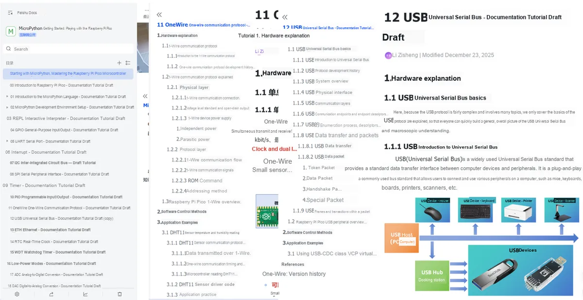

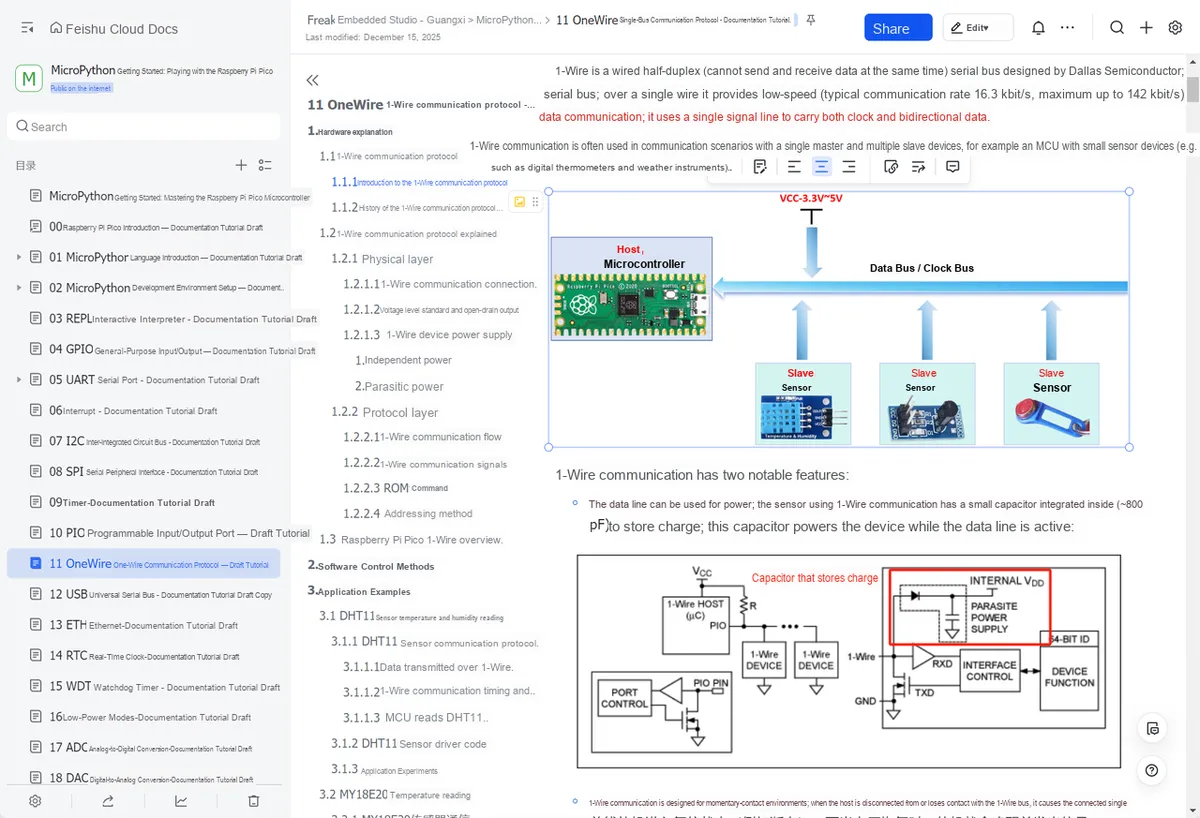
3.2 Quick Start Guide for Scalable Electronic Modules and Hardware Principles
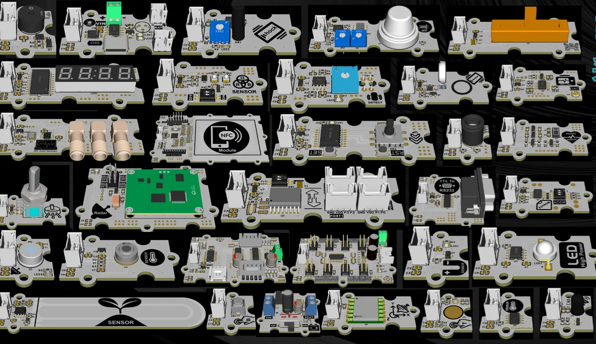
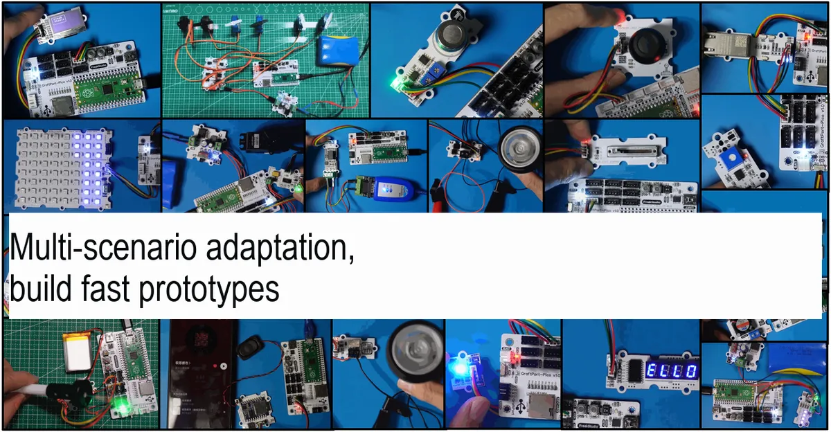
Related Links: GraftSense Sensor Module Documentation (Open Version)
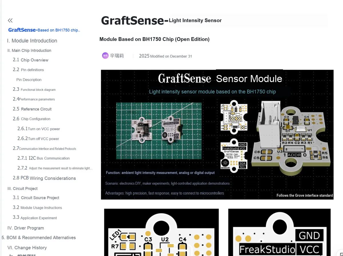
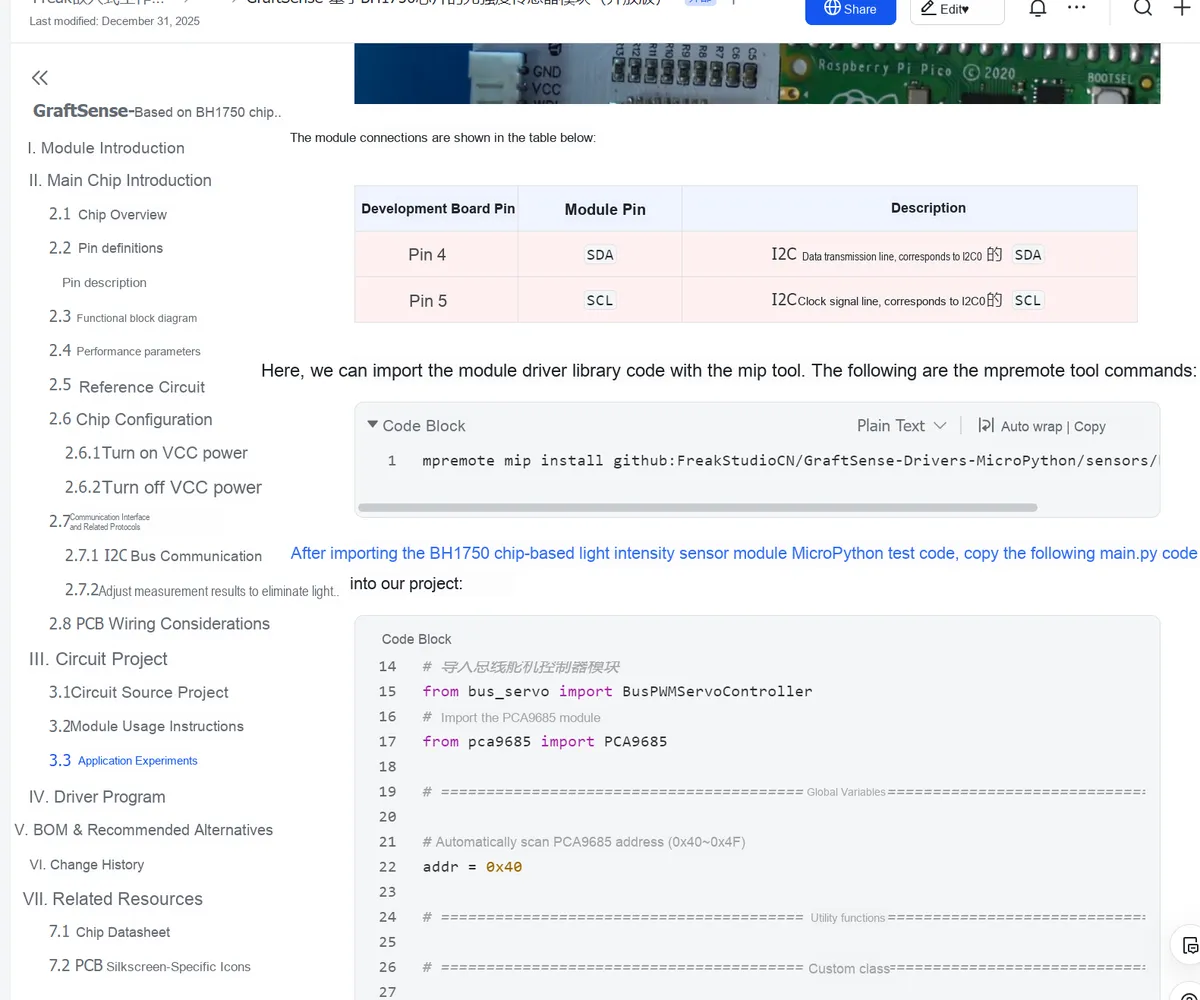
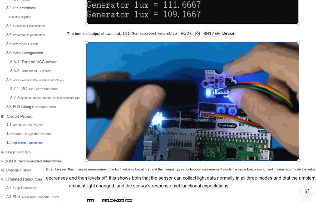
Some modules are summarized as follows, and the list is being updated continuously:
| Module Name | Function Category | Application Areas |
|---|---|---|
| Piranha LED Module | Display / Indicator Module | Maker project indicators, lighting decoration, device status indication, primary and secondary school maker competitions |
| High-Power Single-LED Module Based on OC7140 | Display / Indicator Module | High-brightness lighting, outdoor device indicators, emergency light projects |
| WS2812 Matrix Module | Display / Indicator Module | Dot-matrix display, light animations, creative visual projects, maker competition effects |
| 0.96-inch SSD1306 OLED Module | Display / Indicator Module | Device parameter display, small instrument interfaces, maker project data display |
| PCF8574-Based Eight-Segment Light Bar Digital Display Module | Display / Indicator Module | Numeric counting display, temperature and humidity value display, simple instruments |
| TM1637-Based 4-Digit Digital Display Driver Module | Display / Indicator Module | Countdown timers, counters, small device parameter display |
| MG811 Carbon Dioxide Sensor Module | Gas Sensor Module | Indoor air quality monitoring, agricultural greenhouse CO₂ concentration detection, maker environmental monitoring |
| MQ-Series Electrochemical Gas Sensor Module | Gas Sensor Module | Combustible gas leak detection, smoke monitoring, hazardous gas alarm devices |
| UV Ultraviolet Sensor Module Based on GUVA-S12SD | Environmental Sensor Module | UV intensity monitoring, sunscreen reminder devices, outdoor environmental monitoring |
| DHT11-Based Temperature and Humidity Sensor Module | Environmental Sensor Module | Indoor temperature and humidity monitoring, simple weather stations, maker beginner projects |
| DHT22-Based Temperature and Humidity Sensor Module | Environmental Sensor Module | High-precision temperature and humidity monitoring, agricultural greenhouses, smart home environment control |
| MLX90614-Based Non-Contact Infrared Temperature Module | Temperature Sensor Module | Non-contact temperature measurement, human body temperature detection, equipment surface temperature monitoring |
| DS18B20-Based Temperature Sensor Module | Temperature Sensor Module | Multi-point temperature acquisition, cold chain monitoring, industrial temperature detection |
| BMP280-Based Barometric Pressure and Temperature Sensor Module | Environmental Sensor Module | Weather stations, altitude measurement, drone barometric altitude hold |
| MLX90640-Based Non-Contact Infrared Image Sensor Module | Image Sensor Module | Thermal imagers, human body thermal temperature images, equipment fault thermal detection |
| PT334-Based Flame Sensor Module | Environmental Sensor Module | Fire alarms, flame detection robots, security projects |
| BH1750-Based Light Intensity Sensor Module | Environmental Sensor Module | Illuminance monitoring, automatic dimming systems, agricultural lighting control |
| GL5516-Based Light Intensity Sensor Module | Environmental Sensor Module | Simple light monitoring, automatic streetlight control, maker beginner projects |
| L916-Based Infrared Pyroelectric Human Proximity Sensor Module | Human Sensing Module | Motion-sensing lights, security alarms, automatic door control |
| OH34N-Based Hall Sensor Module | Motion Sensing Module | Motor speed measurement, position detection, magnetic switches |
| PS2 Joystick Module | Human-Machine Interaction Module | Remote-controlled robots, game controllers, gimbal control |
| Slide Potentiometer Module | Human-Machine Interaction Module | Dimming and speed control, parameter adjustment, maker beginner circuit experiments |
| EC11-Based Rotary Encoder Module | Human-Machine Interaction Module | Volume adjustment, menu selection, parameter knobs |
| RK09L-Based Rotary Potentiometer Module | Human-Machine Interaction Module | Analog adjustment, brightness/speed control, experiment debugging |
| TTP223-Based Touch Key Module | Human-Machine Interaction Module | Touch switches, touch panels, maker interactive control |
| Mechanical Key Module | Human-Machine Interaction Module | Device switches, function selection, maker beginner input |
| PCF8574-Based Five-Way Key Module | Human-Machine Interaction Module | Menu navigation, direction control, small control panels |
| Limit Switch Sensor Module | Human-Machine Interaction / Limit Module | Robot travel limits, mechanical positioning, equipment protection |
| ASRPRO-CORE-Based Offline Voice Module | Voice Module | Offline voice control, smart home voice interaction, maker voice projects |
| DY-SV19T-Based Voice Playback Module | Voice Module | Voice announcements, device prompts, storyteller projects |
| MAX9814-Based Electret Condenser Microphone Module | Voice Module | Sound acquisition, recording, voice-controlled projects |
| SNR9816-Based Human Voice Speech Synthesis Module | Voice Module | Text-to-speech, smart prompts, accessibility devices |
| MOS Transistor Level Shifter Module | Signal Conversion Module | High/low level matching, level compatibility between microcontrollers and peripherals |
| Isolated TTL-to-RS485 Module | Communication Module | Industrial networking, long-distance data transmission, PLC communication |
| CH340K-Based USB-to-TTL Module | Communication Module | Microcontroller programming, serial debugging, USB-to-serial |
| MAX3232-Based TTL-to-RS232 Module | Communication Module | Traditional serial communication, industrial control connections, long-distance transmission |
| PN532-Based NFC Communication Module | Communication Module | Near-field communication, access control reading/writing, maker NFC projects |
| HC-08-Based Master/Slave Integrated BLE Bluetooth Module | Communication Module | Bluetooth wireless control, mobile phone device communication, smart home |
| HC-14-Based LoRa Communication Module | Communication Module | Long-distance wireless communication, IoT transmission, outdoor networking |
| CC2530-Based Zigbee Communication Module | Communication Module | IoT networking, smart home, industrial wireless networks |
| Air530Z-Based BeiDou Navigation Module | Positioning Module | Outdoor positioning, drone navigation, vehicle positioning |
| TAS-755C-Based Serial-to-Ethernet Module | Communication Module | Device networking, Ethernet data transmission, remote monitoring |
| AT24C256C-Based EEPROM Module | Storage Module | Parameter storage, power-off retention, configuration record |
| Watchdog module based on the DS1232 chip | System protection module | MCU crash prevention, stable devices, industrial control |
| RTC real-time clock module based on the DS1307 chip | Timing module | Clock display, scheduled tasks, timestamps |
| Clock signal generator module based on the SI5351 chip | Signal generator module | RF signal source, clock synchronization, circuit testing |
| Lithium battery charge/discharge module based on the IP5407 | Power management module | Lithium battery charging, portable device power supply |
| Lithium battery charge/discharge module based on the SY7656 chip | Power management module | High-precision charging, portable power supply, charging case design |
| Adjustable power supply module based on the LM2596S | Power management module | Regulated power supply, adjustable output, lab power supply |
| Low-power solar power management module based on the SPV1050 | Power management module | Solar charging, outdoor portable use, photovoltaic maker projects |
| Serial servo driver module | Drive control module | Robot joints, gimbal steering, robotic arm drive |
| I2C bus 16-channel PWM servo driver module | Drive control module | Multi-servo robots, biomimetic robots |
| Optocoupler-isolated MOSFET single-motor driver module | Motor driver module | DC motor forward/reverse, speed control, power drive |
| I2C bus DC motor driver module | Motor driver module | Smart car, motor speed control, DC drive |
| I2C bus unipolar stepper motor driver module | Motor driver module | Stepper motor control, 3D printing, precision positioning |
| Latching relay module based on the G6KU | Switch control module | High-power device control, energy-saving switch |
| Standard relay module based on the HF46F | Switch control module | Home appliance control, power switch, security systems |
| MOSFET switch relay module based on the JMSL0406 | Switch control module | Medium-power switching, DC loads, fast on/off |
| Cooling fan module based on a MOSFET | Device control module | Device cooling, temperature-linked fan, industrial temperature control |
| Vibration motor module based on a MOSFET | Device control module | Vibration feedback, alarm, haptic feedback for portable devices |
| UV ultraviolet lamp matrix module based on a MOSFET | Device control module | UV disinfection lamp, UV curing, maker UV applications |
| Ultrasonic atomization module based on the FM8118 chip | Device control module | Humidifier, atomizer, maker atomization projects |
| 6-channel direct-connect I2C expansion module | Interface expansion module | I2C device expansion, multi-sensor networking |
| 8-bit IO port expansion module based on the PCF8574 | Interface expansion module | IO port expansion, multi-device control, key expansion |
| 4-channel I2C multiplexer expansion module based on the PCA9546ADR | Interface expansion module | I2C multiplexing, avoiding address conflicts |
| GraftPort-OpenMV expansion board | Interface expansion module | OpenMV vision development |
| Analog-to-digital conversion module based on the ADS1115 chip | Signal Conversion Module | High-precision analog acquisition, sensor data acquisition |
| Digital-to-analog conversion module based on the MCP4725 chip | Signal Conversion Module | Analog output, waveform generator, analog control |
| Serial gyroscope module based on the JY60 | Motion Sensing Module | Attitude detection, self-balancing car, drone attitude control |
| Six-axis gyroscope module based on the MPU6050 | Motion Sensing Module | Robot attitude control, motion-sensing devices |
| Heart rate and blood oxygen sensor module based on the MAX30102 chip | Biosensing module | Heart rate monitoring, blood oxygen detection, wearable devices |
| Transceiver-integrated ultrasonic module based on the RCWL-9623 | Distance measurement module | Car obstacle avoidance, range finder, liquid level detection |
| Laser distance measurement module based on the VL53L0X chip | Distance measurement module | High-precision distance measurement, obstacle avoidance, displacement measurement |
| Single-channel line-tracking module based on the TCR5000L | Robot module | Line-tracking car, maker competitions, path recognition |
| Color recognition module based on the TCS34725 | Vision sensing module | Color recognition, color detection |
| Passive buzzer module | Sound and light alarm module | Prompt tone, alarm sound, maker sound effects |
| Power amplifier speaker module based on the LM386 chip | Audio module | Audio amplification, sound playback, maker audio |
| Breathing and sleep monitoring millimeter-wave radar module based on the R60ABD1 | Radar sensing module | Sleep monitoring, breathing detection, smart home |
| Fall alarm millimeter-wave radar module based on the R60AFD1 | Radar sensing module | Elderly fall alarm, posture detection, security |
| Multi-person trajectory millimeter-wave radar module based on the R60AMP1 | Radar sensing module | Person trajectory tracking, security monitoring, smart spaces |
| Gas concentration measurement module based on the JED-MEMS | Gas sensing module | Gas monitoring, air quality analysis |
| Surface EMG signal amplification and acquisition module | Biosensing module | EMG detection, motion-sensing control, bioelectric maker projects |
| Digital potentiometer module based on the DS3502 | Analog adjustment module | Digital dimming and speed control, programmable parameters, industrial control |
3.3 Rapid Prototype Expansion Board and Teaching Case Library
After you have completed the systematic learning of core knowledge points, we have seamlessly connected you with the GraftPort, a dedicated expansion board suitable for rapid prototyping, and the supporting teaching case library, helping you directly leap from "mastering knowledge points" to "prototype implementation of hands-on mini projects". It truly translates learning outcomes into tangible practical works, forming a complete capability closed loop of "learning → practice → prototype → iteration".
Related Links: Teaching Case Based on GraftPort Expansion Board (Open Version)
Some teaching cases are summarized as follows, and the list is being updated continuously:
Case Name | Core knowledge points to be learned |
|---|---|
Contactless Respiration and Heart Rate Measurement Device | 1. Hardware connection: Learn to connect radar and OLED display via UART and I2C interfaces, and connect the pushbutton to the GPIO port (pull-down mode to prevent false triggering); 2. Data processing: Read radar data and extract respiration and heartbeat values (entry-level data parsing); 3. Interactive operation: The OLED screen displays data in two lines, implementing the logic that a short key press triggers measurement and a long key press stops it; 4. Practical Tips: Be aware that low battery level of lithium batteries may affect data, and learn to avoid common malfunctions. |
Heart Rate and Blood Oxygen Health Monitor | 1. Sensor Usage: Connect the MAX30102 module and learn to collect basic data of heart rate and blood oxygen; 2. Display control: Use the 4-digit nixie tube to switch and display heart rate and blood oxygen, and long press to lock the values; 3. Abnormality judgment: Set the normal range (heart rate: 40-180, blood oxygen: ≥90%), and the LED will flash for alarm when the value exceeds the range; 4. Key Practical Points: Ensure the sensor is firmly attached to the fingertip to avoid light leakage that may interfere with data accuracy. |
Water Quality TDS Detection Device | 1. Analog signal acquisition: Read the data of the TDS sensor via the ADC interface and convert it into the ppm value; 2. Display and Alarm: The OLED displays the TDS value and water quality level; when the standard is exceeded, the buzzer alarms and the LED flashes; 3 . Calibration Tip: Learn to calibrate the sensor with distilled water to obtain more accurate data; 4. Precautions: Be aware of the influence of water temperature on the measurement, and understand the cleaning and maintenance methods for the probe. |
Infrared Temperature Measurement Human Body Induction Alarm Device | 1. Multi-sensor collaboration: Connect the infrared temperature measurement (MLX90614) and human body induction (L916) modules to realize the function of "temperature measurement only when a person is present"; 2. Temperature alarm: Set a threshold of 36.5°C; when the temperature exceeds the threshold, the buzzer will give an intermittent alarm, and the OLED will display the temperature. 3. Power consumption optimization: It detects the human body at a low frequency in standby mode to avoid power waste; 4. Installation Tips: Know the temperature measurement distance and the methods to prevent false triggering of the sensor (avoid direct sunlight, add a lens). |
Integrated Monitoring Station for Soil Temperature, Moisture and Illumination | 1. Multi-bus usage: Master the basic connections of the single bus (for temperature measurement with DS18B20) and dual I2C buses (for light sensing and OLED display); 2. Data conversion: Convert the ADC value of soil moisture into percentage, and convert the illumination value into lux (lx); 3. Display Design: The OLED cyclically displays 3 parameters, with fixed titles to make the interface clearer; 4. Key points to avoid pitfalls: Prevent address conflicts between two I2C devices, and install the sensors separately to avoid interference. |
Touch Key Controlled Fan Speed Regulation Device | 1. PWM Speed Regulation: The fan speed is controlled via PWM signals, with 3 speed settings available (Low/Medium/High/Off); 2. Touch interaction: Use the touch button to switch gears, and the digital tube displays the current gear (0-3); 3. Hardware adaptation: Note that the minimum fan speed shall not be too low (≥20%), otherwise the fan will fail to start; 4. Sensitivity Adjustment: Learn to adjust the sensitivity of the touch buttons to prevent false triggering. |
BeiDou Navigation and Positioning Data Acquisition Device | 1. Serial communication: Connect to the BeiDou module and read positioning data (latitude and longitude, altitude); 2. Data conversion: Convert latitude and longitude to the "degrees-minutes-seconds" format for easier reading; 3. Status feedback: Use an LED to indicate whether positioning succeeds or fails, and prompt the user to move to an open area when positioning fails; 4. Basic Check: Note that the baud rate should be set to 9600 to avoid program freezes caused by data errors. |
Anti-theft Alarm Device with Vibration and Infrared Sensing | 1. Trigger Detection: Detect anomalies via vibration and human body sensors, and trigger an alarm once the system is armed. 2. Status switching: Arm/disarm via key press, with the OLED displaying the current status; 3. Alarm control: When an alarm is triggered, the buzzer sounds and the LED flashes; press and hold the button to reset. 4. Anti-misoperation: Fix the vibration sensor, and add a lens to the human body induction module to narrow the detection range. |
Surface Electromyography Signal Intensity Monitoring Device | 1. Biological signal acquisition: Read the myoelectric signal through the ADC interface, and remove interference via basic filtering; 2. Intensity Display: Convert the signal into percentage and display the OLED status (normal/abnormal); 3. Peak Value and Alarm: Press the key to lock the peak value, and an alarm will be triggered when the signal is out of range (<10% or >80%); 4. Anti-interference: It is required to use shielded wires for connection, and the electrode patches shall be firmly attached to the skin with conductive paste applied. |
Portable ECG Signal Acquisition Device | 1. ECG acquisition: Connect the ECG module, read the ECG signal and filter out interference; 2. Bluetooth transmission: Data is sent to the mobile APP via BLE Bluetooth to enable real-time viewing; 3. Power consumption control: Reduce the sampling rate when no mobile phone is connected to save power; |
Real-time Monitoring and Alarm Device for Smoke Concentration | 1. Gas detection: Connect the smoke module, read the concentration data, and wait for 30 seconds for preheating (until the data stabilizes); 2. Alarm logic: When the concentration is ≥500ppm, the buzzer will alarm intermittently, and the OLED will display the status; 3. Installation Specification: The module shall be installed in a well-ventilated area to avoid gas accumulation that may cause inaccurate data; 4. Data Filtering: Simply process the data to eliminate abnormal fluctuations for more stable display. |
Smart Eye-Caring Desk Lamp | 1. Automatic dimming: The brightness is collected by a light sensor to automatically adjust the brightness of the desk lamp (target: 300 lx); 2. Manual Control: Tap the button to switch the table lamp on/off; long press for stepless dimming (10% - 100%); 3. Eye Care Tips: Set the PWM frequency to 1kHz or higher to avoid eye damage caused by stroboscopic light; 4. Anti-misoperation: Keep the touch keys away from metal surfaces and ensure proper insulation for wiring. |
Succulent UV Supplemental Lighting Controller | 1. Dimming Control: The UV lamp is controlled by a MOS tube, with stepless brightness adjustment via PWM (0-100%); 2. Timer protection: The UV lamp can be turned on for a maximum of 8 hours, and will automatically shut down when the time limit is exceeded to prevent burning the plants; 3. Manual operation: Rotate the potentiometer to adjust the brightness, and press the button to switch the light (with 10ms debounce to prevent accidental touch); 4. Safety Notes: Keep the UV lamp away from the human body, place the equipment in a dry place, and avoid watering to prevent short circuits. |
Noise Detector | 1. Audio acquisition: Read the sound intensity via a microphone module and convert it into a dB value (relative value); 2. Exceedance Reminder: When the noise level exceeds 85dB, the LED will flash and the OLED will display the prompt "Noise Exceedance"; 3. Data Export: Export the day's noise data via Bluetooth for easy viewing; 4. Calibration Instructions: Note that the dB value is a reference value, and it can only be accurate after being calibrated with professional equipment. |
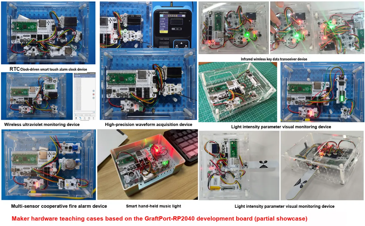
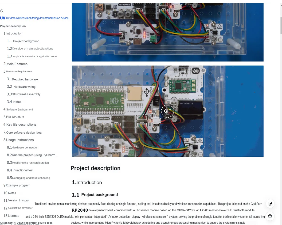
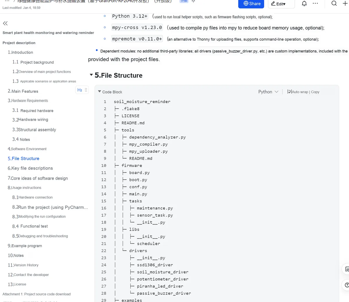
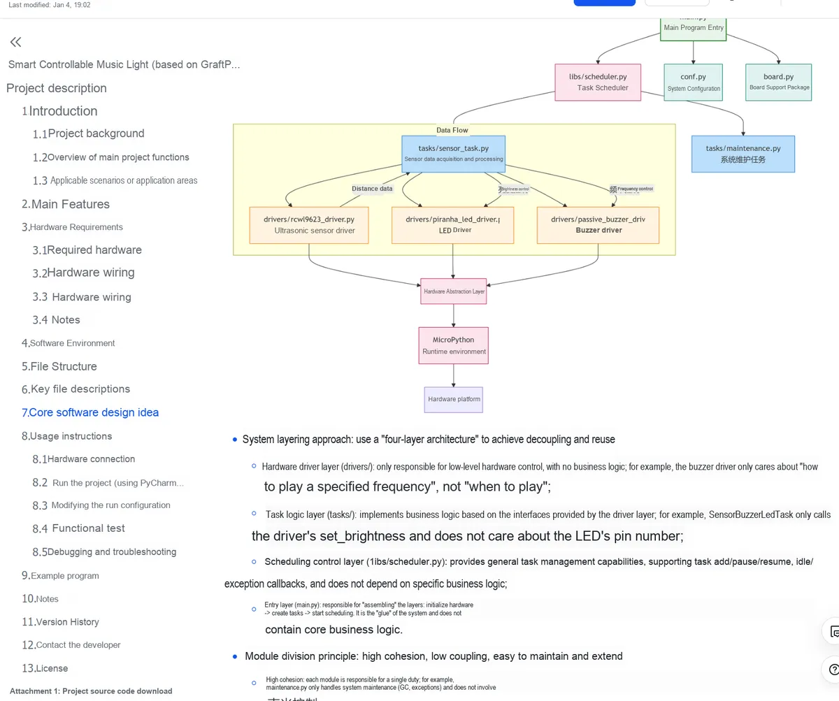
3.4 Advanced Python Programming Tutorial
We have two featured tutorials supporting this course: *The Most Beginner-Friendly Object Oriented Programming Tutorial Across the Internet* and *A Quick Guide to Mastering Python Parallel Computing*. Different from those scattered online tutorials that either focus too much on theory or only cover a single scenario, these two tutorials form a complete closed loop following the flow of "principle breakdown → code practice → project implementation":
- The Object Oriented tutorials deepen understanding by integrating case studies of embedded sensor projects;
- Tutorial on Parallel Computing Focusing on Concurrency Performance Optimization in Embedded Scenarios
| Module Name | Included chapters |
|---|---|
| Getting started | - Introduction to object-oriented design methods - Basic concepts of object-oriented programming |
| Core implementation of classes and objects | - Creating classes with Python- Adding attributes to custom classes- Adding methods to custom classes- PyCharm code tag tips- Data encapsulation in custom classes- Improving readability with type annotations - @property decorator: wrapping methods as attributes- Relationships between classes- Inheritance and the Liskov substitution principle - Calling parent class methods from a subclass - Outputting logs with the logging module - Installing and using SourceTrail - Static methods and class methods- __slots__ magic method - Polymorphism, method overriding, and the open-closed principle - Duck typing and "file-like object" - Multiple inheritance and plotting with PyQtGraph - PyCharm auto-generated comments - Implementing composition and saving to CSV - Multi-file organization: module and package |
| Exceptions and debugging | - Exceptions and syntax errors - Raising exceptions - Exception handling: try/except statements - Checking the input data type - Context managers and the with statement - Exception hierarchy and custom exceptions - Python programming principles and conventions - Assertions and defensive programming |
| Data Types and Structures | - Python built-in data types: the object root class - Object and Type - Class and Instance - The relationship between Object, Type and Class - Common compound types: tuples and named tuples - Strings and the __doc__ attribute - Dictionaries - Lists and list comprehensions - Implementing stacks, queues and deques with lists - Sets - Enumerations and the enum module - Queues (FIFO, LIFO, priority queues) - collections container data types - Extending built-in data types - Overriding the magic methods of built-in types - Common data structures: linked lists, trees, hash tables |
| Functions and Interfaces | - Functions and event-driven frameworks - Callback functions - Positional, default, variable-length and keyword arguments - Differences between functions and methods, and lambda anonymous functions - Interfaces and abstract base classes - Implementing interfaces with Zope - Protocols and interfaces |
| Strings and Serialization | - Strings and character encoding - String formatting and the format method - Byte sequence types and mutable byte strings - Regular expressions and the re module - Serialization and deserialization - Definition and implementation of serializing Web objects |
| Advanced Practice | - Parallelism and concurrency: threads and processes - Comprehensive object-oriented example: real-time sensor data plotter |
| Module Name | Included chapters |
|---|---|
| Parallel Computing Basics | - Basic concepts of parallel computing |
| Python Multithreading | - Python Multithreading - Basic concepts, switching process, GIL mechanism and the producer-consumer model - Python Multithreading - The threading module, creating and querying threads, and daemon threads - Python Multithreading - Thread synchronization (Part 1) - Based on mutex locks, recursive locks and semaphores - Python Multithreading - Thread synchronization (Part 2) - Based on condition variables, events and barriers - Python Multithreading - Running threads on a timer - Python Multithreading - Communication based on queues - Python Multithreading - Using thread pools and evaluating multithreading performance |
| Python Multiprocessing | - Python Multiprocessing - The multiprocessing module, creating and naming processes, getting process IDs, creating daemon processes - Python Multiprocessing - Data synchronization between processes - Based on mutex locks, recursive locks, semaphores, condition variables and events - Python Multiprocessing - Data sharing between processes - Based on shared memory and data managers - Python Multiprocessing - Secure data transfer between processes - Based on queues and pipes - Python Multiprocessing - Process pool Pool |
| Python Asynchronous Programming | - Python Asynchronous Programming - Basic concepts, event loop and callback mechanism - Python Asynchronous Programming - Managing and scheduling coroutines |
| Tutorial Summary | - Tutorial Summary |
It not only helps you build a reusable knowledge system, but also directly supports the secondary development requirements of hardware projects.
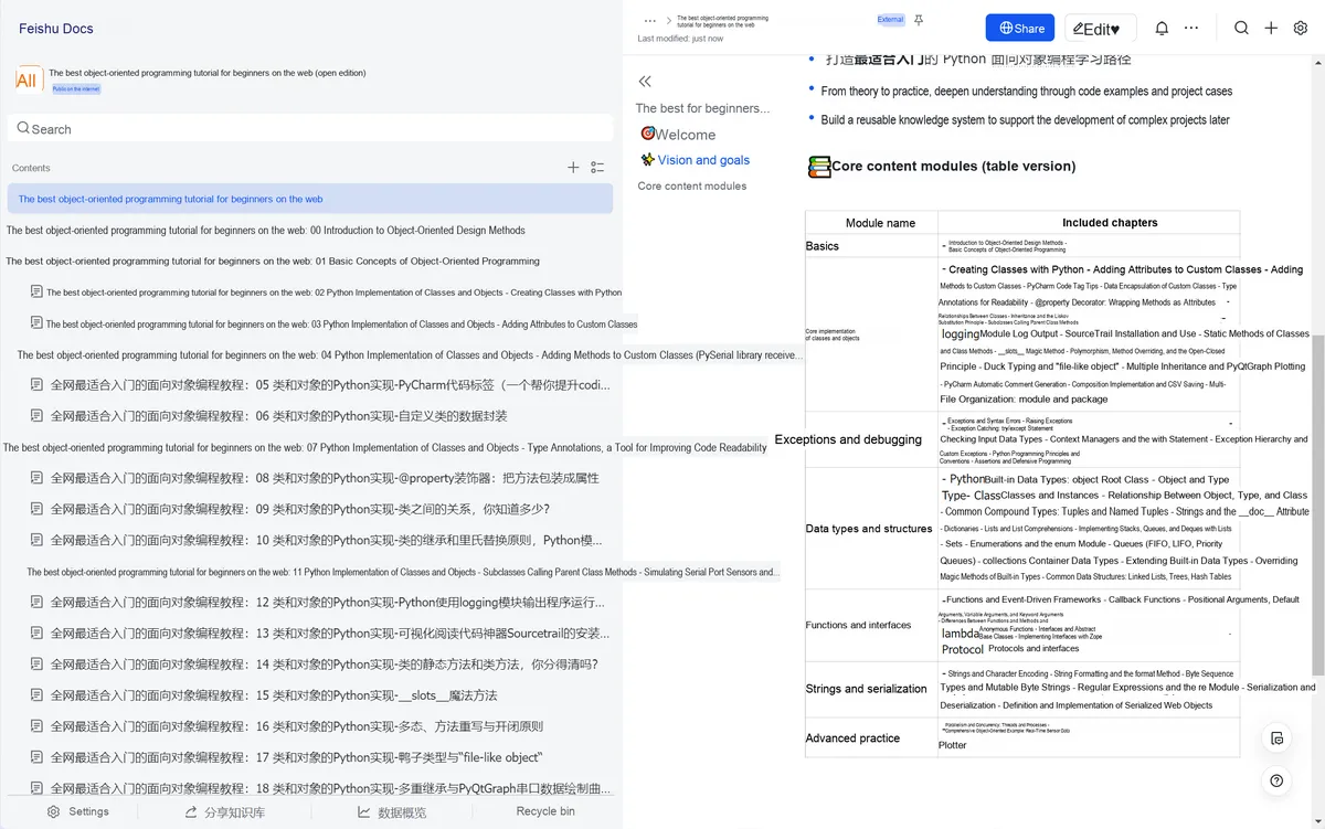
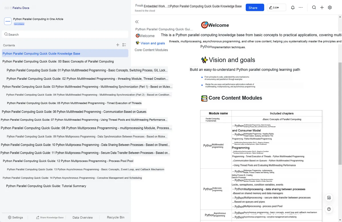
- Object Oriented Programming: https://f1829ryac0m.feishu.cn/wiki/space/7596544900980591570? ccm_open_type= lark_wiki_spaceLink&open_tab_from= wiki_home
- A Quick Guide to Python Parallel Computing: https://f1829ryac0m.feishu.cn/wiki/space/7596547761378429917? ccm_open_type= lark_wiki_spaceLink&open_tab_from= wiki_home
3.5 Full Open Source for Cases and Hardware
3.5.1 Fully Open-Source Code
- Object Oriented Design: All driver and demo codes are developed following the industrial-grade Object Oriented (OOP) paradigm, in strict compliance with the SOLID design principles, featuring clear class structure and standardized interfaces. It not only fits practical usage, but also helps you grasp the core idea of "Modularization and layered design", so that you can develop professional coding thinking right from the start.
- Standardized Comment System: The code is accompanied by standardized comments that cover all dimensions including file descriptions, class/method functions, parameter/return value explanations, and exception prompts. Key logic and boundary conditions are clearly marked, so even beginners can quickly understand the code logic without repeatedly consulting materials, doubling learning efficiency.
- Fully open-source and traceable: All codes are 100% open-source, accompanied by coding specification documents, with comment formats, naming conventions and design concepts fully disclosed, which can not only be directly applied to projects, but also be used to learn some embedded coding techniques in reverse through the open-source codes.
Repository Address: https://github.com/leezisheng/elegance-devkit-v1_DemoCode
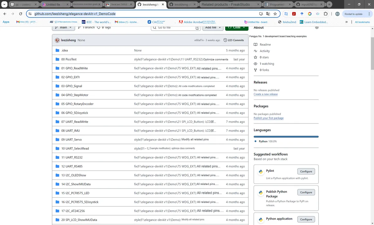
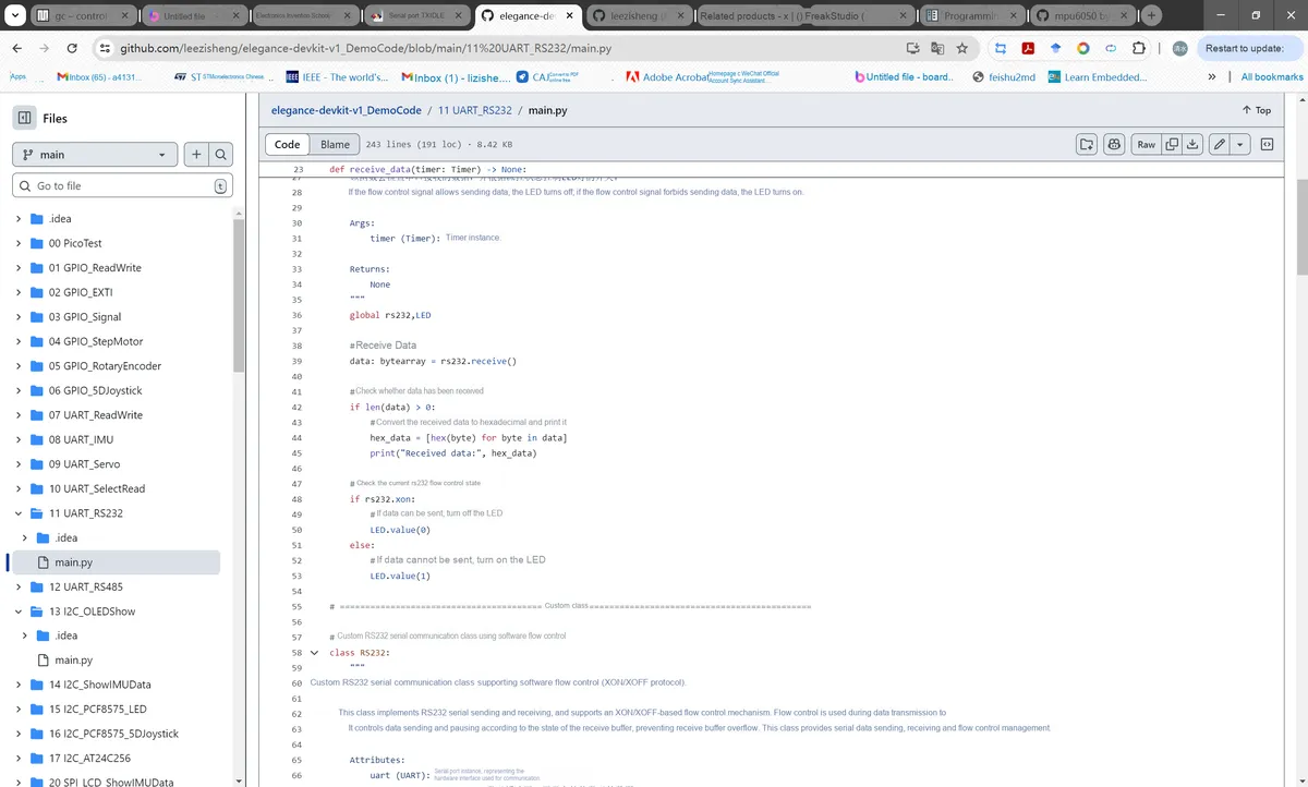
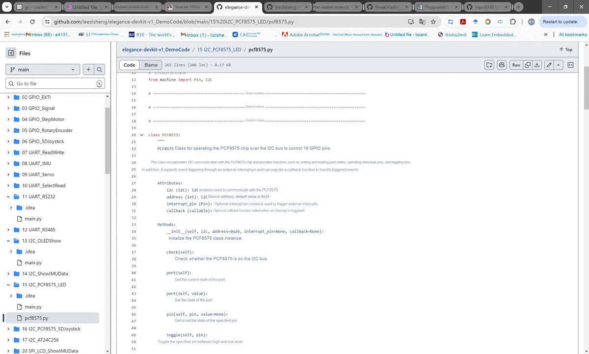
3.5.2 Fully open source hardware of the development board
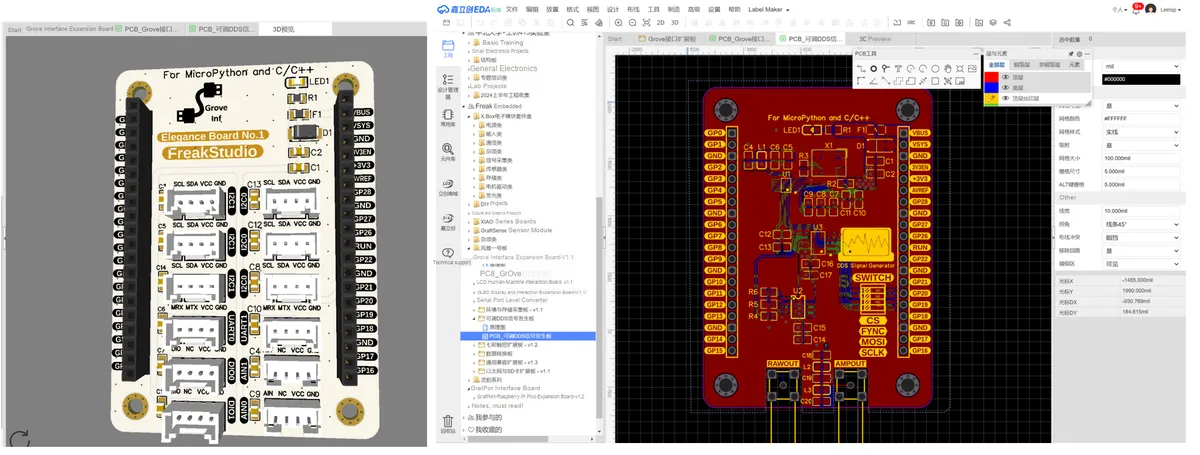
The full series hardware design of Fengya No. 1 board is 100% open source and has been fully launched LCKFB Open Source Plaza, where you can directly obtain the full set of editable hardware design files (schematic diagram, PCB layout, BOM Bill of Material, soldering guide):
- Open-source platform with traceability: All hardware design files are publicly available on the LCKFB Open Source Square, which can be directly downloaded for replication, modification and optimization;
- Hand-soldering Friendly Design: We focus on optimizing package selection, and most resistors and capacitors on the board adopt the universal 0805 package (instead of the miniature 0402/0603 packages), which features large pin spacing and easy identification, so even beginners can easily complete hand soldering without professional placement equipment, lowering the threshold for hardware replication, maintenance and DIY modification;
3.6 Dedicated uPyPI Platform
Similar to PyPI's package management, it enables one-click installation of driver libraries and supports third-party library publishing:
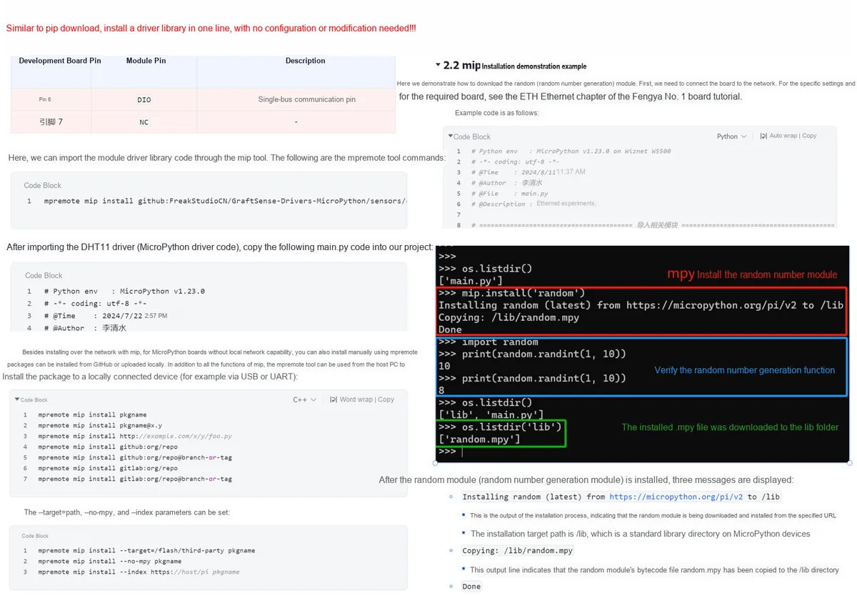
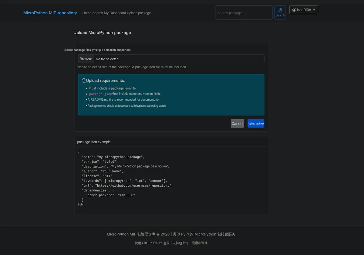
3.x Bipes-based MicroPython Graphical Tutorial - DIY for Primary and Secondary School Students / Zero Beginners
As a dedicated expansion board tailored for rapid prototyping, GraftPort's exclusive supporting component (this module is not included in the core course of the Fengya No. 1 Board), we have specially launched this lightweight graphical programming tutorial. Bipes replaces traditional code writing with drag-and-drop blocks, allowing users to implement core functions such as hardware control, Data Acquisition, and logical judgment without memorizing MicroPython syntax:
- It is especially suitable for zero-base enthusiasts and teenage learners to get started quickly, or for developers to iterate ideas rapidly during the prototype verification phase;
- Paired with the Plug and Play hardware module for the GraftPort expansion board, you can directly access resources such as sensors, OLED displays, and communication modules in the graphical interface. Simply drag and drop blocks to generate executable MicroPython code, which can be run and verified on the expansion board in real time, significantly lowering the threshold from "an idea" to "a runnable prototype".
This tutorial covers the entire process from basic graphical instructions to complex prototype projects, including cases such as sensor data visualization, interactive device construction, and IoT node development. It not only helps you quickly verify hardware solutions, but also enables a natural transition to pure code development through the corresponding display of graphics and code, laying a solid foundation for your subsequent in-depth learning of MicroPython.
Some tutorials are summarized as follows, and the list is being updated continuously: Graft Dev Kit - Bipes-Based Graphical Programming Teaching Documentation
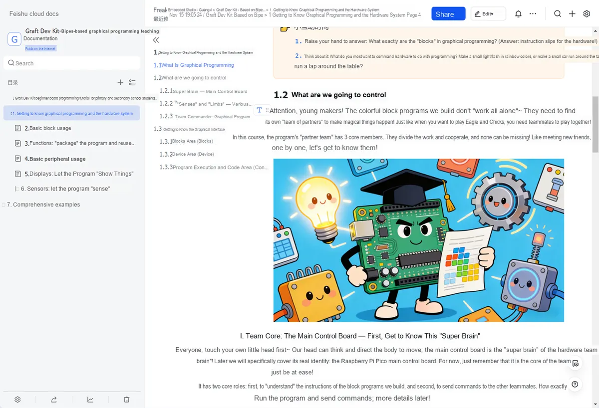
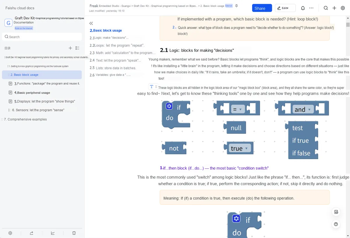
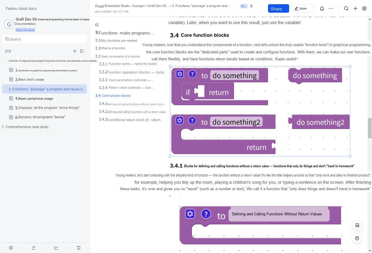
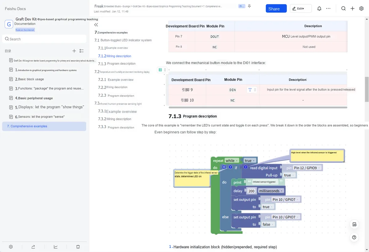
IV. What after-sales services are available?
- 🤝 After-sales QQ Group + Direct Answers from the Author: No Stuck Points in Your Learning Journey
- The after-sales exchange QQ group has product/tutorial authors personally answering core questions: whether you get stuck in code debugging, make mistakes in hardware soldering, or encounter difficulties in project implementation, you can get accurate and down-to-earth solutions, ensuring no one falls behind on the learning path.
- 📚 Continuously updated learning resources: One-time purchase, lifetime benefits
- Official Account Column: regularly shares MicroPython practical skills, advanced embedded development tips, and excellent user project cases;
- Dynamic update of Wiki documents: core materials such as hardware usage guides, code examples, and driver library descriptions will be updated in real time along with user feedback and technical upgrades, always keeping the content timely and practical, so you don't have to worry about not being able to learn the latest usage methods.
- 🛡️ Reliable hardware guarantee: risk-free shopping, more reassuring learning experience
- We promise no compromises in hardware after-sales services, so you can shop with peace of mind and use it without worries:
- 7-Day No-Reason Return Policy: After receiving the development board, if it remains unopened and free of physical damage, you are eligible for a 7-day no-reason return, eliminating concerns about "wrong purchase or inapplicability";
- 15-Day Replacement Service: Within 15 days after receiving the goods, if there is a hardware failure caused by non-artificial damage, you can directly apply for a replacement, which saves the time cost of waiting for repair and will not delay your learning progress;
- Lifetime technical support: For issues related to soldering, debugging and adaptation encountered during the use of the hardware, the author will provide full guidance throughout the process. This is not a "sell-and-ignore" service; instead, the author will stand by you until you fully master and make the most of the development board.
5. Relevant web addresses and open-source code repositories
Elegance V1 Board Address: https://github.com/FreakStudioCN/elegance-devkit-v1
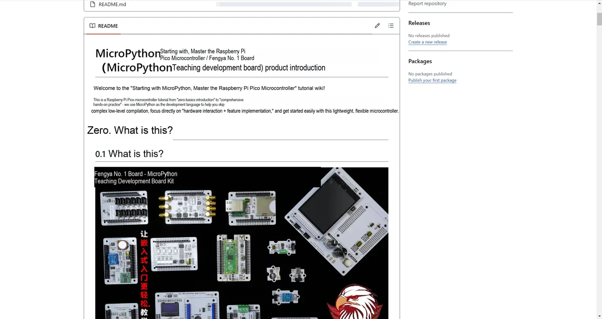
Warehouse Address: https://github.com/orgs/FreakStudioCN/repositories
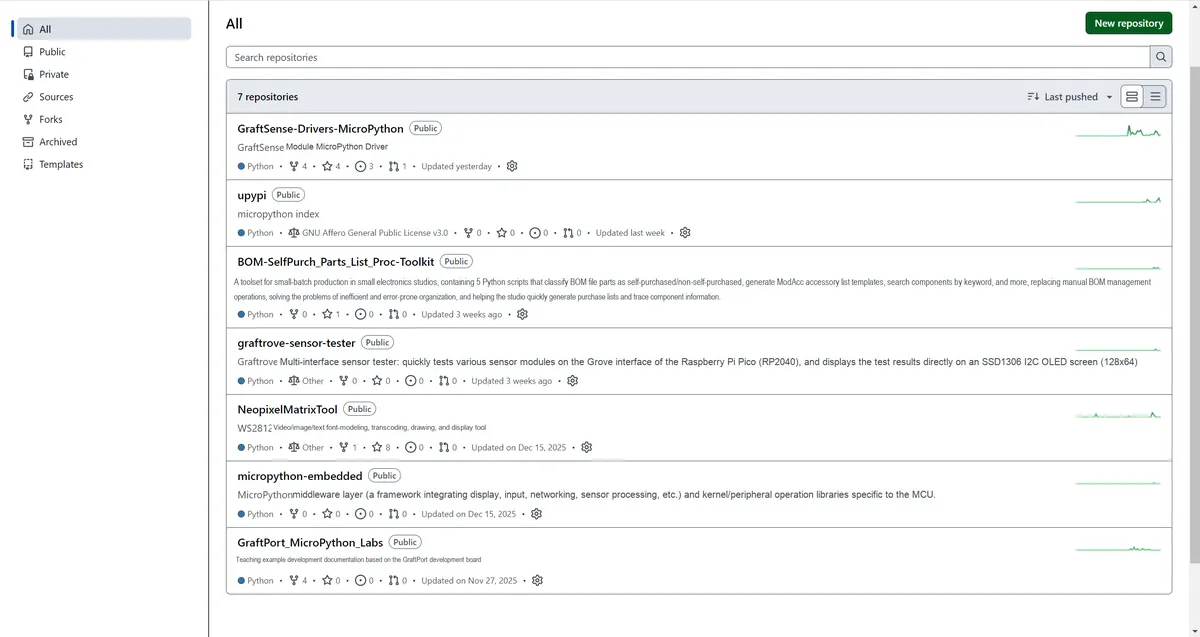
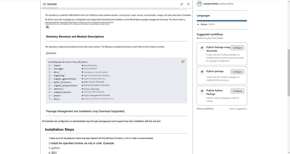
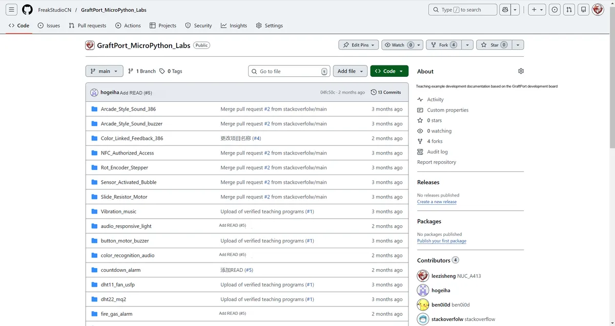
Wiki URL: https://freakstudio.cn/

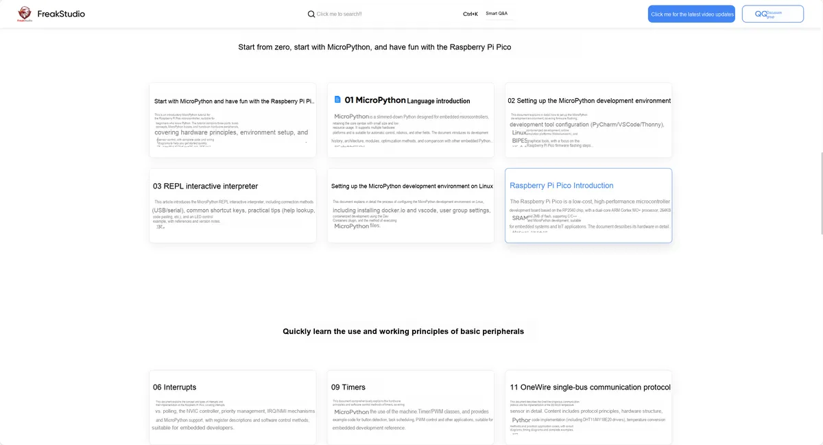

uPyPi Address: https://upypi.net/
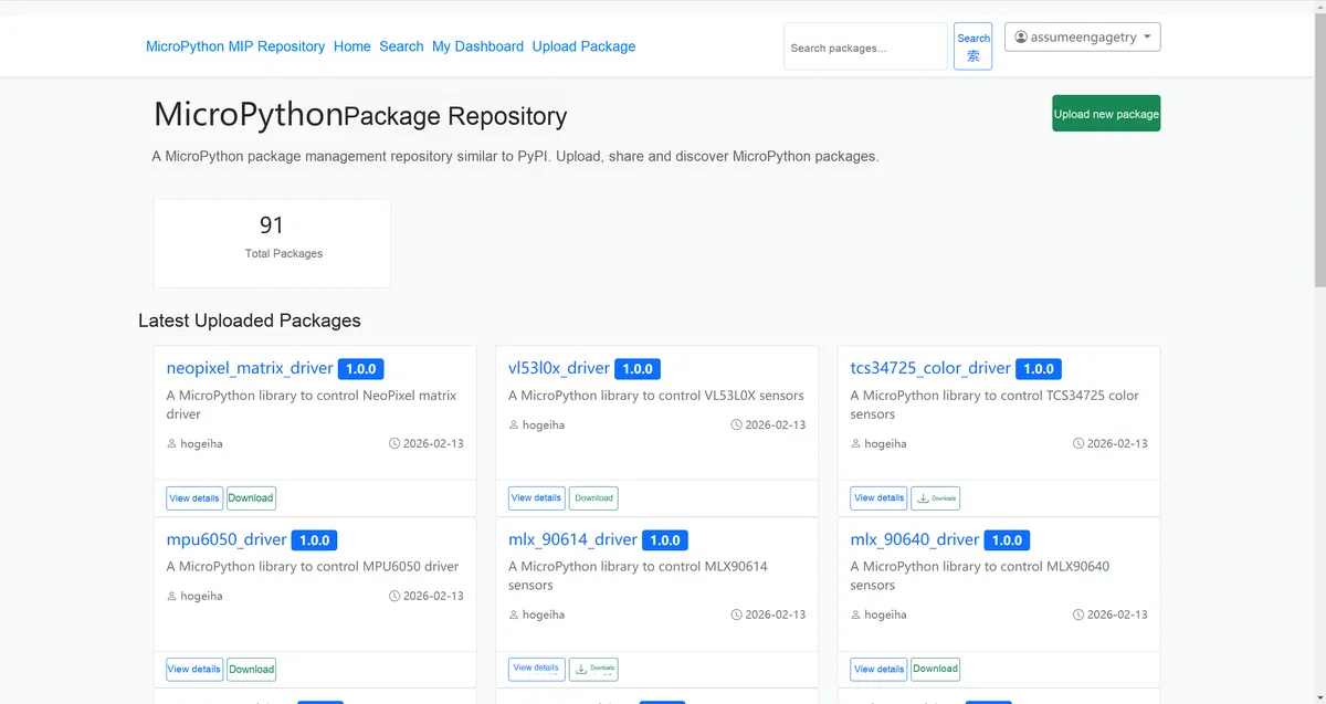
Graphical programming software address: https://freakstudiocn.github.io/pages/ui/
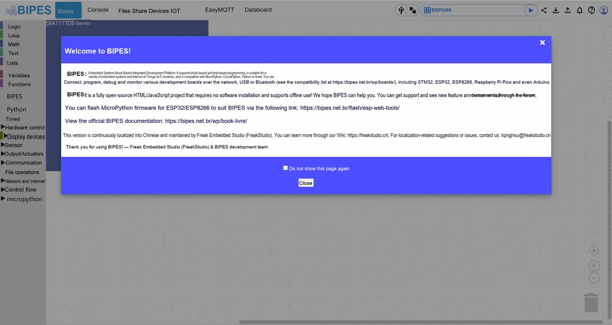
References
None.
Knowledge Base Version Record
Version Number | Modifier | Time | Content |
v1.0 | Li Zisheng | 2025/12/27 | Initialize the Knowledge Base |
v1.1 | Li Zisheng | 2025/01/23 | Section 4: Summary of Key Points has been added. |
v1.2 | Li Zisheng | 2025/01/24 | Added support for uMial. |
v1.2.1 | Li Zisheng | 2025/01/25 | A delivery list table has been added, so a stepper motor driver board needs to be added accordingly. |
v1.3.0 | Li Zisheng | 2026/02/15 | Changed the relevant web pages. |
v1.4 | Li Zisheng | 2026/02/15 | Added the address of Fengya No. 1 Board. |
v1.5 | Li Zisheng | 2026/03/22 | Added the images of Lichuang · ColorEasyPico2 development board. |