
Contents
- Project Description
- 1. Introduction
- 2. Main Functions
- 3. Hardware Requirements
- 4. Software Environment
- 5. File Structure
- 6. Description of Key Documents
- 7. Core Idea of Software Design
- 8. Instructions for Use
- 9. Sample Program
- 10. Notes
- 11. Version Record
- 12. Contact the Developer
- 13. Licensing Agreement
- Appendix I: Project Source Code Download
- Appendix II: Hardware Module Reference Materials
- Version Record
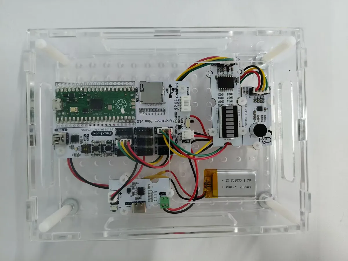
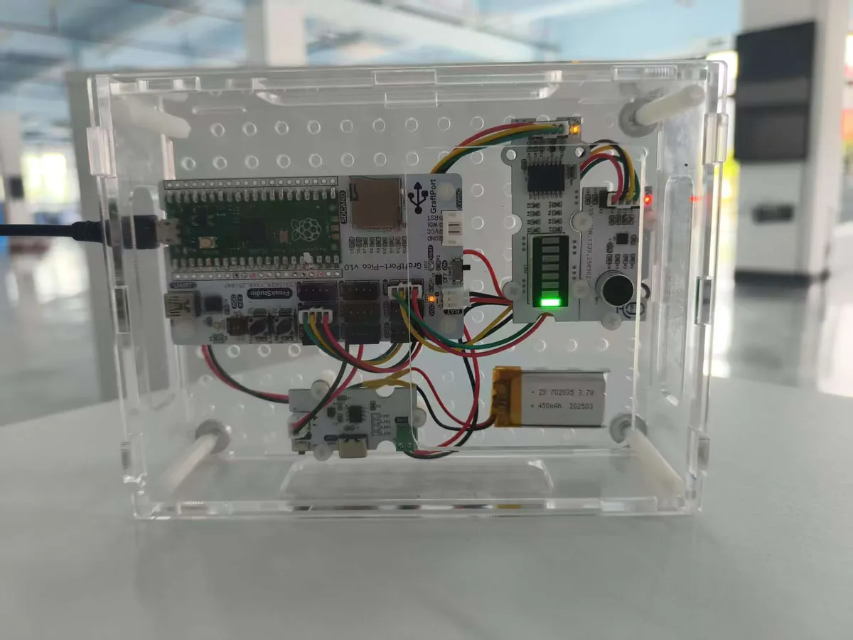
Project Description
1. Introduction
1.1 Project Background
This project is based on the GraftPort-RP2040 development board, and integrates an electret condenser microphone module based on the MAX9814 and an 8-segment bar digital tube module based on the PCF8574 chip to implement an integrated "audio energy acquisition and display" system. It incorporates the lightweight task scheduling and exception handling mechanisms of MicroPython to ensure stable system operation.
1.2 Overview of Main Functions of the Project
This project is developed based on MicroPython. Its core function is to collect audio signals in real time via an electret condenser microphone module based on the MAX9814, calculate audio energy through an audio frequency analyzer, and then display the audio energy level via an 8-segment bar LED module based on the PCF8574 chip; it supports on-board key interrupt to switch task start/stop, has built-in automatic garbage collection (GC) to avoid memory leaks, and is equipped with exception capture and rate-limited printing for convenient problem locating.
1.3 Applicable Scenarios or Application Area
- Music Visualization: Displays audio energy in real time to provide visual assistance during music playback;
- Environmental Monitoring: Serves as a simple sound level meter for environmental noise monitoring;
- Teaching Demo: for
MicroPythontask scheduling,ADCData Acquisition,I2Ccommunication, audio analysis and other knowledge points in practical teaching; - Smart Home: Integrated into smart home devices to provide audio-visual interactive features.
2. Main Functions
- Real-time audio energy detection: collect audio signals every 10ms via the electret condenser microphone module based on MAX9814 to calculate the audio energy;
- Real-time display via LED strip light: The 8-segment bar digital tube module based on the PCF8574 chip provides real-time display of the current audio energy level, with a total of 8 levels;
- Key Interrupt Interaction: The onboard key triggers a falling-edge interrupt, which can switch the core task between "run/pause"; when paused, Data Acquisition and display update will be stopped.
- Automatic memory management: Detects memory when idle and automatically triggers
GCif the memory usage is below the threshold, preventingMicroPythonfrom crashing due to memory leaks; - Exception Fault Tolerance Mechanism: When an exception is thrown during task execution, the stack trace will be fully printed with rate limiting enabled to avoid log spamming;
- Flexible board-level adaptation: based on
board.pyto decouple pin mapping, supporting subsequent expansion to otherRP2040development boards.
3. Hardware Requirements
3.1 Hardware Required
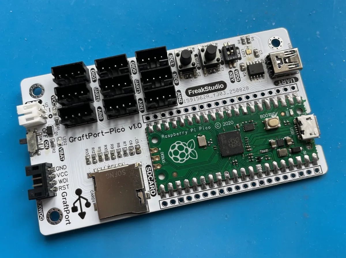
This project is based on the GraftPort-RP2040 development board as the main controller:
Other required modules include:
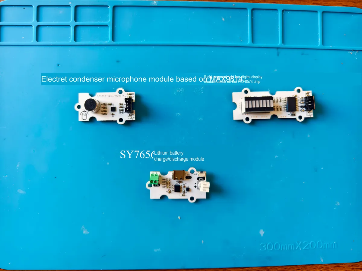
- GraftSense: MAX9814-based Electret Condenser Microphone Module (analog output, connected to
ADCpin; digital output, connected toGPIOpin for gain control); - GraftSense - An 8-segment bar digital tube module based on the PCF8574 chip (
I2Ccommunication, address range0x20~0x27); - GraftSense-SY7656 Lithium Battery Charge-Discharge Module (compatible with polymer lithium batteries, outputs 5V voltage, equipped with a
Type-Ccharging port); - Onboard buttons: By default, the development board's fixed pins (
Pin 18, pull-up input) are used, requiring no additional wiring. - Onboard LED: By default, it uses the fixed pin of the development board (
Pin 25) and requires no additional wiring.
3.2 Hardware Connection
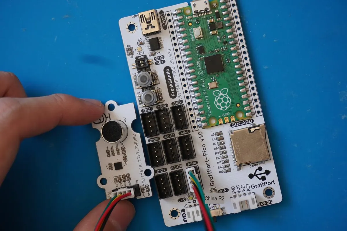
Electret condenser microphone module based on MAX9814: Connected via PH2.0 connecting cable to ADC0 interface (analog input)
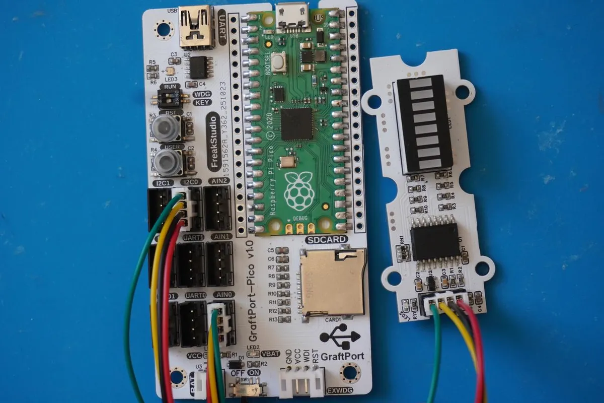
8-segment bar digital tube module based on PCF8574 chip: connect to PH2.0 connector cable to access I2C0 interface;
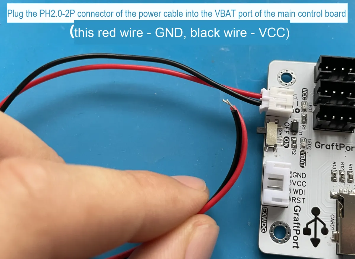
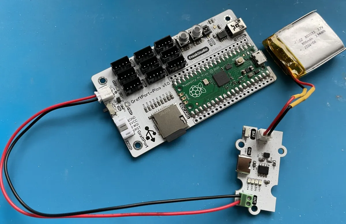
Lithium Battery Charge and Discharge Module: BAT interface connects to the lithium battery, and the OUT interface supplies power to the main control board via a PH2.0-2P connection cable.
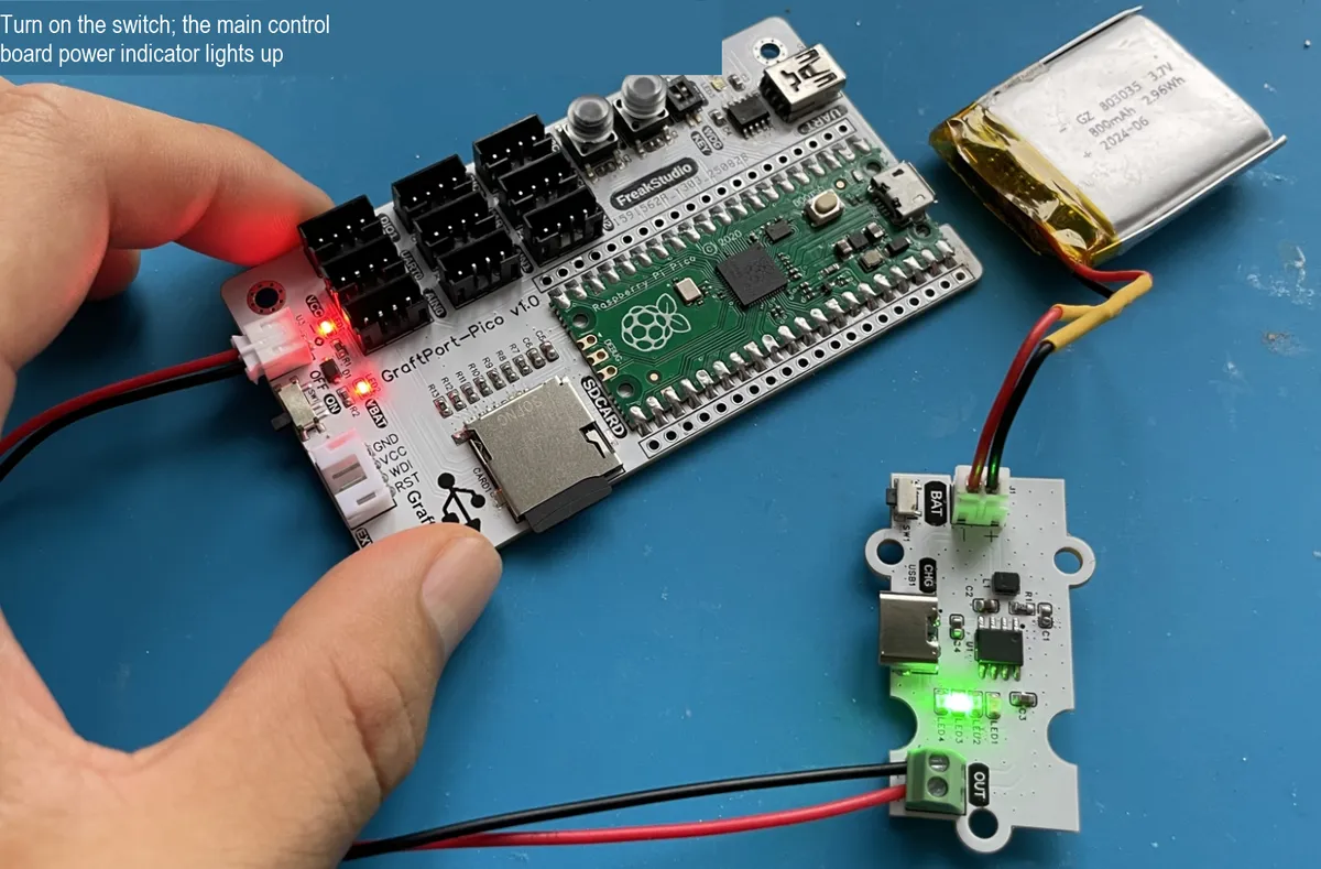
3.3 Structural Assembly
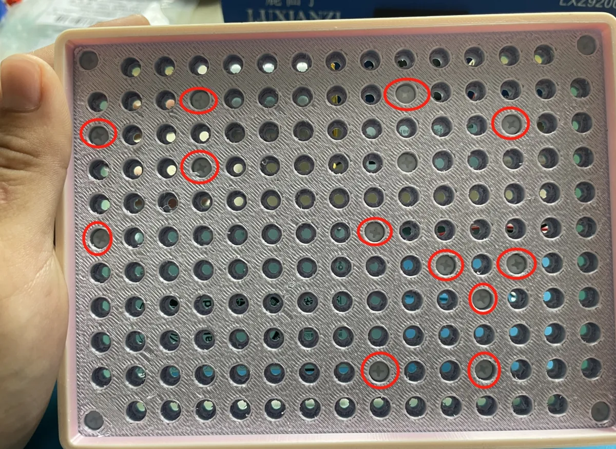
First, use M3 plastic pillars to fix each module and the main control board to the bottom plate of the housing (M3 screw holes are pre-drilled on both the main control board and the housing):
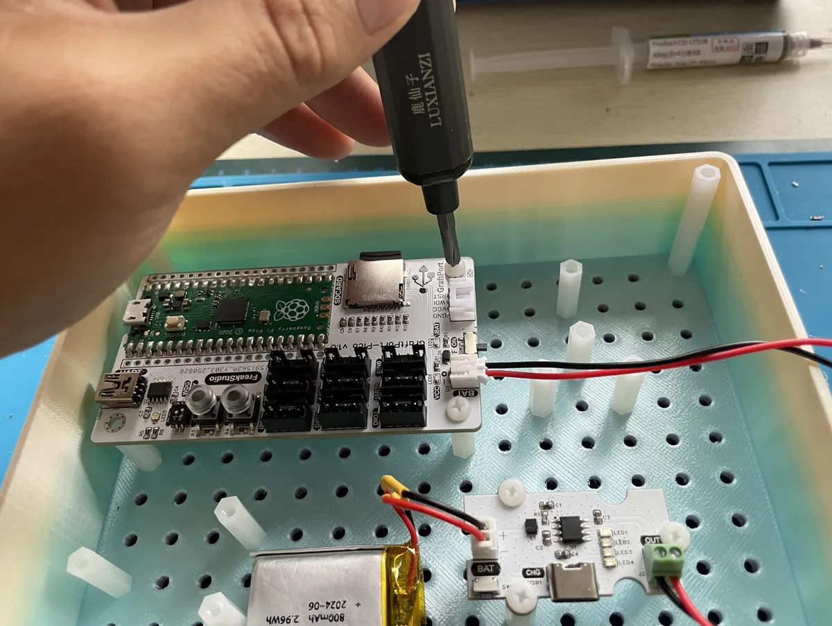
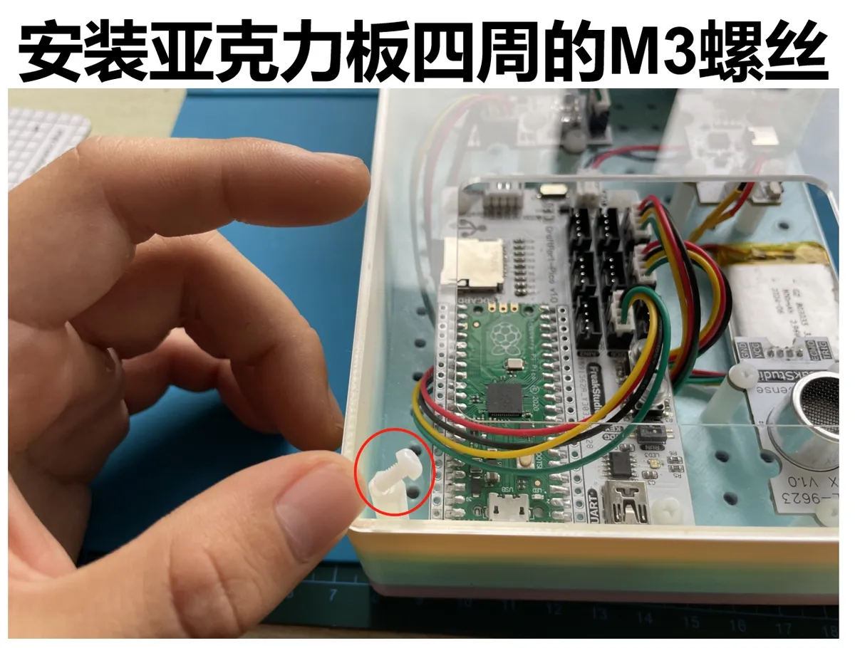
Next, secure the housing around its perimeter using M3 plastic pillars, then fasten M3 screws into the corresponding positions to complete the assembly:
3.4 Notes
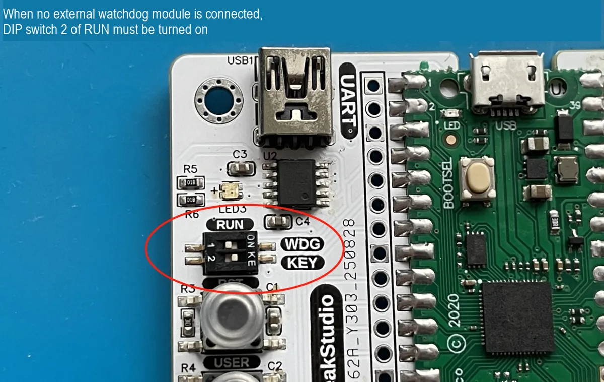
When the main control board is not connected to an external watchdog module, the RUN DIP switch 2 must be turned on:
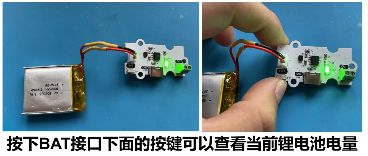
The lithium battery charge-discharge module supports power level display, and you can charge it via the following Type-C interface:
4. Software Environment
- Core Firmware:
MicroPython v1.23.0(adaptation for GraftPort-RP2040 required, with support formachine.Pin/I2C/UART/ADC/Timermodules); - Development IDE:
PyCharm(for code writing, uploading and debugging, supportingMicroPython REPLinteraction); - Supporting Tools:
Python 3.12+(optional, for running local helper scripts);mpy-cross v1.23.0(used to. pyfiles compile into. mpyto reduce the memory usage of the development board, optional);mpremote v0.11.0+(replacesThonnyfor file upload, supports command-line operations, optional);
- Dependency Modules: No additional third-party libraries are required; all drivers are custom-implemented and provided along with the project files.
5. File Structure
audio_responsive_light
├─ .flake8
├─ LICENSE
├─ README.md
├─ tools
│  ├─ dependency_analyzer.py
│  ├─ mpy_compiler.py
│  ├─ mpy_uploader.py
│  └─ README.md
├─ firmware
│  ├─ board.py
│  ├─ boot.py
│  ├─ conf.py
│  ├─ main.py
│  ├─ tasks
│  │  ├─ maintenance.py
│  │  ├─ sensor_task.py
│  │  └─ __init__.py
│  ├─ libs
│  │  ├─ __init__.py
│  │  ├─ TFT_mic
│  │  └─ scheduler
│  └─ drivers
│     ├─ __init__.py
│     ├─ pcf8574_led_driver
│     └─ max9814_mic_driver
└─ examples
   └─ README.md
6. Description of Key Documents
main.py: the project entry point, whose core logic includes:- Power on and delay for 3 seconds (wait for hardware to stabilize), initialize the onboard
LED,MAX9814microphone,PCF8574chip, and buttons (including interrupt registration); - hardware initialization: electret condenser microphone module based on MAX9814, 8-segment bar LED module based on PCF8574 chip;
- Create
sensor_taskinstance (pass in the audio analyzer andLEDstrip light instance and configuration parameters), and encapsulate it as a scheduler task with a period of 10ms; - Initialize
Scheduler(software timer with a scheduling period of 5ms), add tasks and start scheduling, then enter an infinite loop; - Define
button_handlerinterrupt callback (for toggling task start/stop),fatal_hangblocking function (for critical error handling).
- Power on and delay for 3 seconds (wait for hardware to stabilize), initialize the onboard
tasks/sensor_task.py: core business task,key logic of the micTaskclass:__init__: initializes the audio analyzer and theLEDstrip light instance;tick: Executed once every 10ms, the process is "read microphone signal → analyze audio energy →LEDbar light update display";
tasks/maintenance.py: System maintenance module, key functions:task_idle_callback: Triggered when the scheduler is idle; if it detects that the memory usage is lower thanGC_THRESHOLD_BYTES(100000 bytes by default), it will executegc.collect ();task_err_callback: Triggered when an exception is thrown by a task, prints the full traceback (preferentially usessys.print_exception), then delays forERROR_REPEAT_DELAY_S(1 second by default) to prevent screen flooding;- Supports reading configurations from
conf.py, and uses default values when no configuration is provided to ensure compatibility.
drivers/xxx_driver: A hardware driver module, which all adopts the "instantiation + method call" mode, only exposes hardware-related control interfaces and shields underlying details:max9814_mic_driver:The MAX9814Micclass reads analog voltage values via theADC, controls gain throughPin, and provides theread_normalizedmethod to read normalized audio signals;pcf8574_led_driver:The PCF8574class controls theI2C-enabledPCF8574chip, while theLEDBarclass provides thedisplay_levelmethod to control the display level of theLEDbar graph.
libs/TFT_mic.py: audio frequency analyzer,key logic of the AudioFrequencyAnalyzerclass:- Initialization: pass in
MAX9814Micinstance, and set the sampling parameters; sample_and_analyze: Collect a segment of audio signal and calculate its energy (or other features).
- Initialization: pass in
board.py: A board-level pin mapping module that defines theBOARDSdictionary (including the fixed pins ofGraftPort-RP2040and the mapping ofI2C/DIO/ADCinterfaces), and provides interfaces such asget_fixed_pinandget_i2c_pinsto achieve "decoupling of board-level configuration and business logic"; to extend support for other development boards later, you only need to add sub-items toBOARDS.conf.py: User configuration file. The parameters that need to be manually defined by the user include:I2C_INIT_MAX_ATTEMPTS(number of retries for sensor initialization),I2C_INIT_RETRY_DELAY_S(retry interval in seconds),ENABLE_DEBUG(debug print switch),AUTO_START(whether the task starts automatically). If not defined, the system will use the default values.
7. Core Idea of Software Design
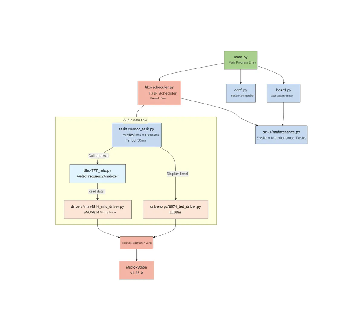
- System Hierarchy Concept: Adopt a "four-tier architecture" to achieve decoupling and reuse
- Hardware Driver Layer (
drivers/): It is only responsible for the low-level control of hardware and contains no business logic. For example, a microphone driver only focuses on "how to acquire audio signals" and does not care about "when to display". - Task Logic Layer (
tasks/): Implements business logic based on the interfaces provided by the driver layer. For example,micTaskonly calls the driver'sread_normalizedmethod to obtain data, without concerning itself with the ADC pin of the microphone; it only callsdisplay_levelto display the level, without concerning itself with theLED'sI2Cconfiguration. - Scheduling Control Layer (
libs/scheduler.py): Provides general task management capabilities, supports task addition/pause/resume, idle/exception callbacks, and is independent of specific services; it uniformly manages the execution timing of all tasks through a soft timer to ensure rational allocation of system resources. - Entry layer (
main.py) : responsible for "assembling" each layer, initializing hardware → creating tasks → starting scheduling, is the "glue" of the system, does not include core business logic; handle hardware exceptions and user interaction to ensure stable system startup and operation.
- Hardware Driver Layer (
- Principles for Module Division: High cohesion, low coupling, facilitating easy maintenance and expansion
- High Cohesion: Each module is only responsible for the Single Responsibility Principle, for example,
maintenance.pyonly handles system maintenance (GC, exceptions) and does not involve data display;sensor_task.pyonly handles the logic of audio Data Acquisition and display, and does not care about hardware initialization; each driver module only encapsulates the control methods for the corresponding hardware. - Low coupling: Modules interact via "interfaces" instead of directly manipulating internal variables, for example,
micTaskobtains energy viaAudioFrequencyAnalyzer.sample_and_analyze ()without directly accessing the registers ofADC; it displays levels viaLEDBar.display_level ()without directly operating theI2Chardware. - Scalability: When adding new hardware (such as other sensors), simply add the corresponding driver under
drivers/and create a new task undertasks/without modifying existing code; when expanding the development board, simply add the pin mapping inboard.pywithout affecting the business logic; when adding new display content, simply modify the display logic ofmicTaskwithout involving any changes at the hardware layer.
- High Cohesion: Each module is only responsible for the Single Responsibility Principle, for example,
- Core Mechanism: Ensuring System Stability and User Experience
- Task scheduling mechanism: Implemented based on a soft timer
(Timer (-1)), with a scheduling cycle of 5ms and a core task cycle of 10ms. It judges whether a task is due for execution through "counter accumulation" to avoid timer nesting conflicts; it supports dynamic task pause and resume to respond to user operations. - Data update mechanism: Adopt a "real-time update" strategy, updating the
LEDdisplay every 10ms to ensure real-time display; meanwhile, through audio energy analysis, the energy is mapped to 8LEDlevels for intuitive display. - Interactive feedback mechanism: Key interrupt callbacks take "immediate effect": when paused, Data Acquisition and display updates stop immediately to avoid unresponsive user operations; when sensor initialization fails, a "clear error alert"(
LEDblinking + terminal message) is triggered to facilitate troubleshooting of hardware connection issues. - Fault Tolerance Mechanism: All critical operations (such as hardware control, data reading) are wrapped with
try-exceptto prevent the failure of a single module from crashing the entire system; for example, a microphone reading failure will not affect the operation of task scheduling, and the automatic memory reclamation mechanism prevents memory leaks during long-term operation. - Task Execution Section:
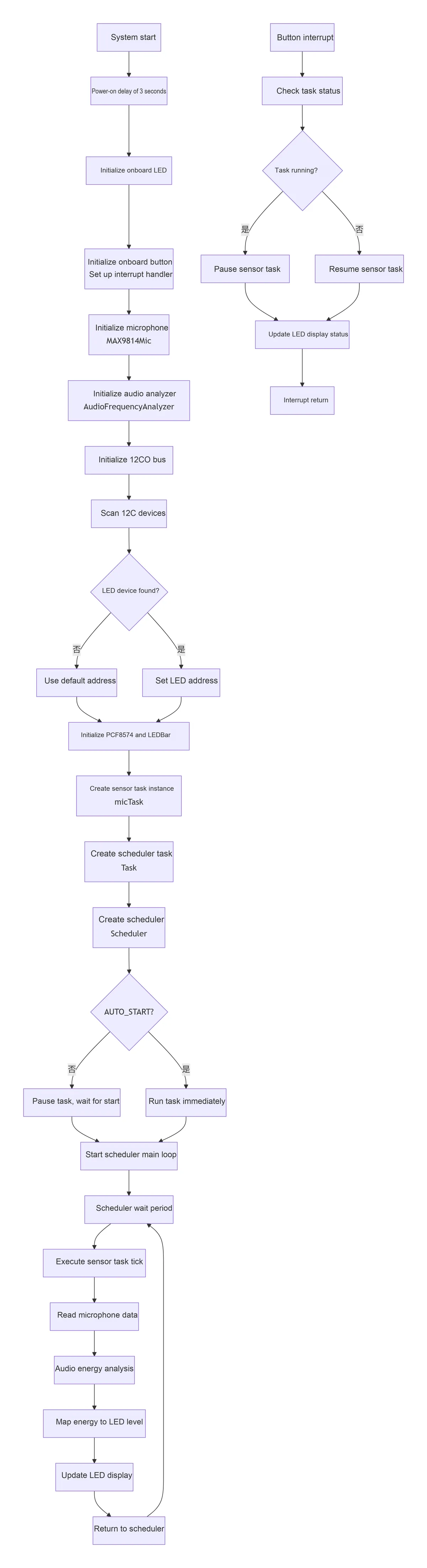
- Task scheduling mechanism: Implemented based on a soft timer
8. Instructions for Use
8.1 Hardware Connection
Connect the main control board, each sensor module and the battery according to the connection method specified in the "hardware requirements";
8.2 Run the Project (Using PyCharm + MicroPython Plugin)
Open PyCharm and install the corresponding MicroPython plugin.
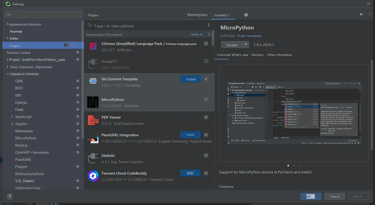
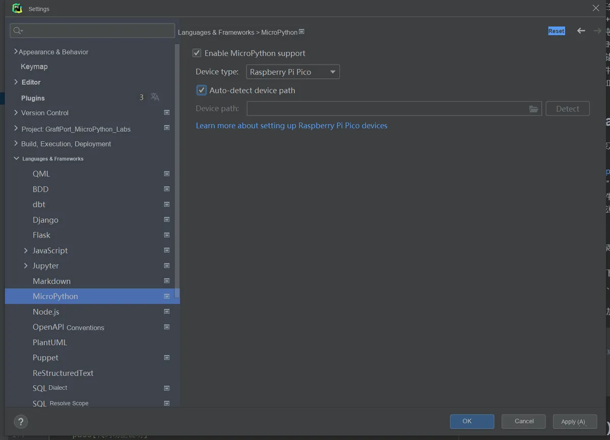
In the plugin, select Target Device (Target Device) as RP2040, and enable Auto-detect device path (Auto-detect device path).
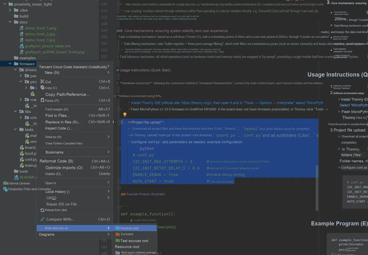
Set Project/firmware as the project root directory.
Modify the runtime configuration:
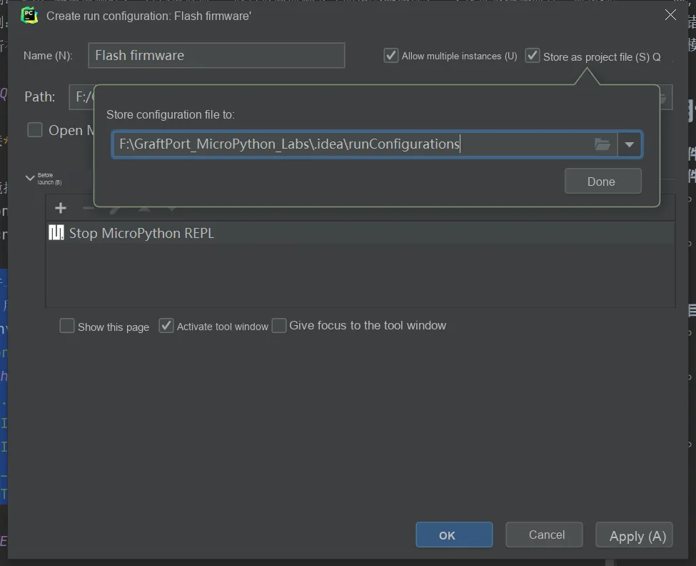
- Check Allow multiple instances (
Allow multiple instances) - Select Store as Project File (
Store as project file) - Click OK to save the configuration.
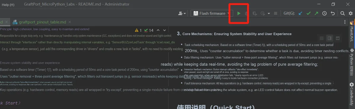
Click the IDE green triangle button in the upper right corner to run, and you can start uploading the firmware and executing the project.
8.3 Modification of Running Configuration
You can configure conf.py to modify or add parameters as needed, for example:
# conf.py example configuration
ENABLE_DEBUG = True            # Whether to enable debug printing
AUTO_START = True              # Whether to run tasks automatically at startup
8.4 Functional Testing
Audio energy detection: emit sounds of different intensities near the microphone and observe LED strip light display to see if it changes accordingly;
Button Switch: Press the onboard button to pause the task (stop Data Acquisition and display update), and press it again to resume.
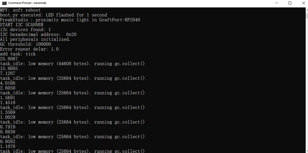
The terminal output is as follows:
8.5 Debugging and Problem Localization
- If
I2Cdevice does not respond, check the hardware connection, power supply, andI2Caddress configuration; - If
PCF8574LEDdoes not light up, check whether theI2Caddress is correct (0x20~0x27), and use anI2Cscanner to confirm the device address; - If
MAX9814microphone outputs no data, check theADCpin connections and gain control pin configuration;
9. Sample Program
There are no other reference sample codes for this project, you can directly firmware make modifications in the folder.
10. Notes
- Sensor-related:
- Electret condenser microphone module based on MAX9814 requires appropriate sound pressure conditions, and avoid being used under extremely high sound pressure;
- Microphones should be avoided from prolonged exposure to extremely high sound pressure levels to prevent damage.
- Hardware Connection Related:
- The 8-segment bar digital tube module based on the PCF8574 chip 's
I2Caddress may range from0x20 to 0x27, and the system will automatically scan and use the first address found;
- The 8-segment bar digital tube module based on the PCF8574 chip 's
- Software Version Related:
MicroPython v1.23.0 or later versions must be used;- Debug printing will occupy a certain amount of memory, so it is recommended to turn it off during official use.
- Function Usage Related:
- The task cycle (10ms) is not recommended to be set too small, otherwise it may increase the system load;
- Automatic
GCthreshold adjustment is recommended based on actual memory usage.
11. Version Record
- v1.0.0 (2025-10-10): Initial version by Hou Junhan:
- Supports
MAX9814real-time audio energy detection; - Implement the 8-segment bar digital tube module based on the PCF8574 chip for real-time display;
- Supports key interrupt to switch task start/stop;
- Adapted to the GraftPort-RP2040 development board.
- Supports
12. Contact the Developer
If you have any questions or need assistance, please contact the developer via the following channels :
📧 Email: 10696531183@qq.com
💻 GitHub: https://github.com/FreakStudioCN
13. Licensing Agreement
In this project, except for machine and other MicroPython official modules (under the MIT license), all driver and extension codes written by the author are released under the Creative Commons Attribution-NonCommercial 4.0 International (CC BY-NC 4.0) Licensing Agreement.
You are free to:
- Share — to copy, distribute the work in any medium or in any form
- Derivative Works — modify, transform, or create based on this Work
Only the following conditions shall be complied with:
- Attribution — You must give appropriate credit, provide a link to the Licensing Agreement, and indicate if changes were made. You may do so in any reasonable manner, but not in any way that suggests the licensor endorses you or your use.
- Non-commercial Use — You may not use this work for commercial purposes.
- Proper Citation Method — You may clearly indicate the source in code comments, documentation, demo videos, or project descriptions.
Copyright belongs to FreakStudio.
Appendix I: Project Source Code Download
https://github.com/FreakStudioCN/GraftPort_MicroPython_Labs/tree/main/audio_responsive_light
Appendix II: Hardware Module Reference Materials
GraftSense - Electret Condenser Microphone Module Based on MAX9814
GraftSense - An 8-segment Light Bar Digital Tube Module Based on the PCF8574 Chip
GraftSense-SY7656 Lithium Battery Charge-Discharge Module
GraftPort - Raspberry Pi Pico Expansion Board (Open Edition Template Files)
Version Record
Document Version | Date of Modification | Modifier | Modified Content |
V1.0.0 | 2025-11-03 | Hou Junhan | Draft the initial version of the document. |
V1.1.0 | 2026-01-04 | Li Zisheng | Final version. |