Contents
- I. Module Introduction
- II. Introduction to Main Chips
- 2.1 Chip Overview
- 2.2 Pin Definition
- 2.3 Functional Block Diagram
- 2.4 Performance Parameters
- 2.5 Reference Circuit
- 2.6 Chip Configuration
- 2.7 Communication Interfaces and Related Protocols
- 2.8 PCB Routing Precautions
- III. Instructions for Circuit Engineering and Module Usage
- 3.1 Circuit Source Engineering
- 3.2 Module Usage Instructions
- 3.3 Application Experiment
- IV. Drivers
- 5. BOM & Recommended Alternative Parts
- VI. Revision History
- VII. Relevant Materials
- 7.1 Chip Datasheet
- 7.2 Unique Icons for PCB Silk Screen
I. Module Introduction
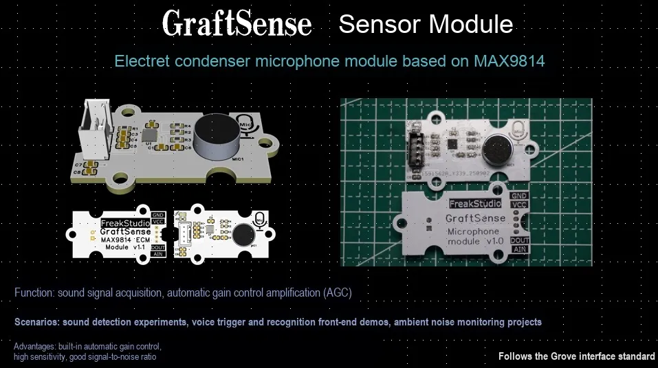
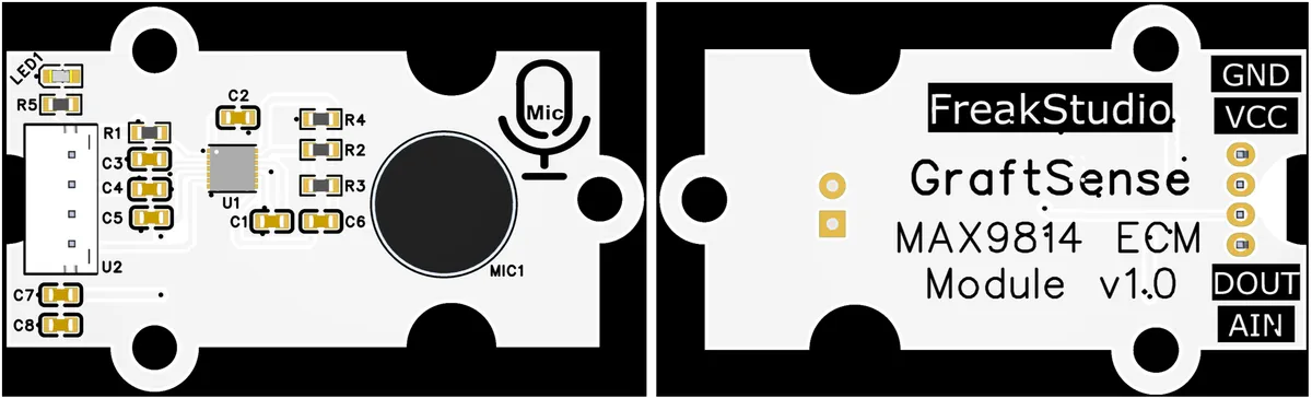
Electret Condenser Microphone Module Based on MAX9814 Centering on the MAX9814 chip that integrates Automatic Gain Control (AGC) and low-noise bias, this module is designed with on-board non-inverting amplifier circuit, sensor interface (supporting DOUT for gain control and AIN for analog output), as well as filtering and indicator circuits. It can efficiently collect audio signals and provides three gain adjustment levels of 40dB/50dB/60dB. Suitable for scenarios such as maker audio acquisition, speech recognition and portable recording, it is a low-cost, high-quality audio front-end solution.
II. Introduction to Main Chips
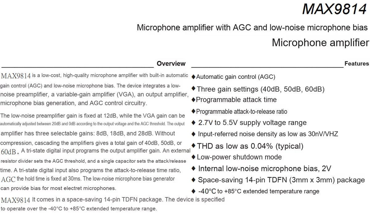
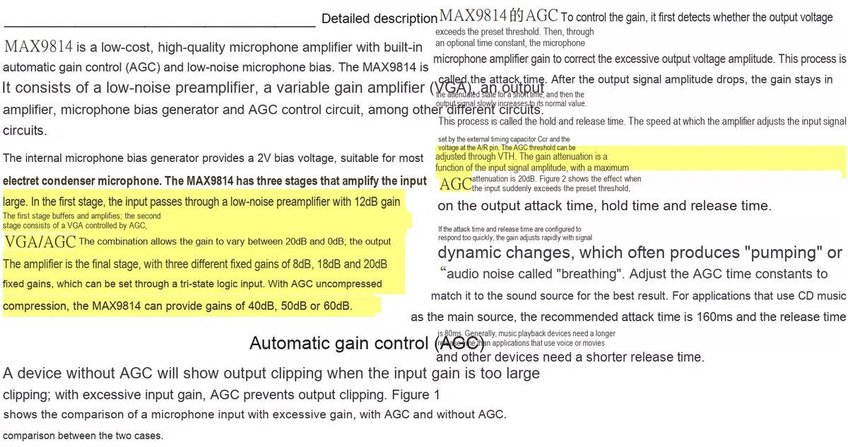
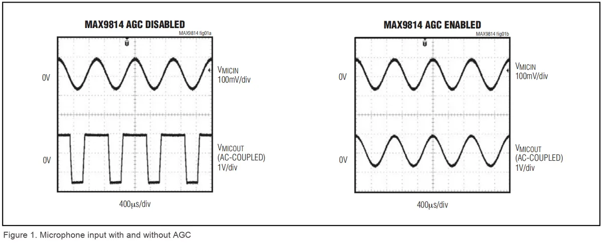
This module is mainly based on MAX9814, a microphone amplifier chip featuring AGC and low-noise microphone bias circuit.
2.1 Chip Overview
2.2 Pin Definition
2.3 Functional Block Diagram
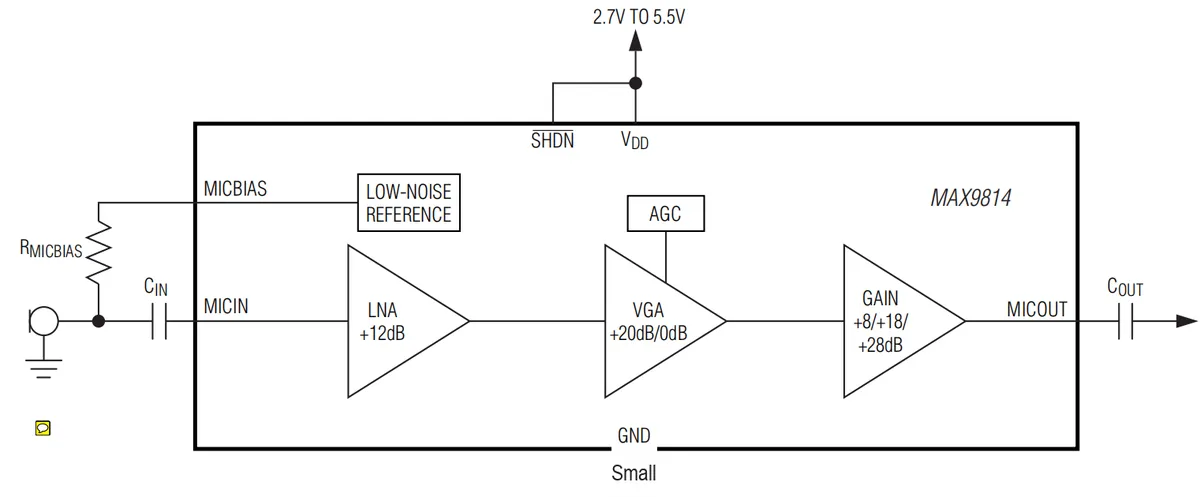
LOW-NOISE REFERENCE(Low-Noise Reference Module): Generates the microphone bias voltage (MICBIAS) to supply power to the electret microphone while ensuring low-noise performance.LNA(Low Noise Amplifier): provides a fixed gain of + 12dB, which preliminarily amplifies the microphone input signal and suppresses noise.VGA(Variable Gain Amplifier): Capable of achieving gain adjustment of + 20dB/0dB under the control ofAGC, to adapt to audio inputs with different loudness levels.AGC(Automatic Gain Control): controls the gain ofVGAto stabilize the loudness of the output signal.GAINAmplifier: Offers three selectable gain levels of + 8/+ 18/+ 28dB to further amplify the signal.SHDN(shutdown pin): Controls the chip to enter the low-power shutdown mode.VDD: Chip power supply pin, with a power supply range of 2.7V to 5.5V.GND: Ground pin, which provides the reference ground for the circuit.MICIN: Microphone signal input pin, which receives the coupled microphone signal.MICOUT: Amplified audio signal output pin, which outputs the coupled signal.
2.4 Performance Parameters
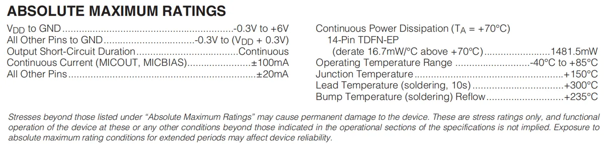
- Power supply voltage (
VDDtoGND):-0.3V to + 6V; - Voltage of other pins to ground:-0.3V to (
VDD+ 0.3V); - Output short-circuit duration: Continuous;
MICOUT,MICBIASpin continuous current:±100mA;- Continuous current of other pins:±20mA;
- Continuous Power Dissipation (
TA= 70°C, 14-PinTDFN-EPPackage): 1481.5 mW (Derating by 16.7 mW per °C above 70°C); - Operating temperature range:-40℃ to + 85℃;
- Junction Temperature:+ 150℃;
- Pin soldering temperature (10s):+ 300℃;
- Reflow temperature for bump soldering:+ 235℃;
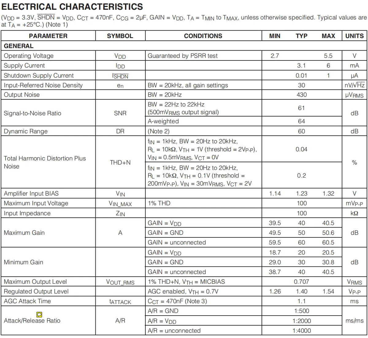
- Operating Voltage (
VDD): 2.7V~5.5V; - Supply Current (
IDD): Typical 3.1mA, Maximum 6mA; - Shutdown supply current (
I_SHD): typically 0.01 μA, maximum 1 μA; - Input-referred noise density (
en): 30 nV/√Hz (at 20 kHz bandwidth, full gain setting); - Output Noise: 430μVRMS (20kHz bandwidth);
- Signal-to-noise ratio (
SNR): 61dB (bandwidth 22Hz~22kHz, 500mVrms output);A-weighted 64dB; - Dynamic Range (
DR): 60dB; - Total Harmonic Distortion plus Noise (
THD+ N): Typical 0.04%(under conditions such as fn= 1kHz); Typical 0.2%(under another condition); - Amplifier input bias (
VIN): 1.14V ~ 1.32V, typical 1.23V; - Maximum input voltage (
VIN, MAX): 100mVp-p(1% THD); - Input Impedance (
ZIN): Typical 100kΩ; - Maximum Gain (
A):- When
GAIN=VDD: 39.5~40.5dB; - When
GAIN=GND: 49.5~50.6dB; GAIN59.5~60.5dB when not connected;
- When
- Minimum Gain:
- When
GAIN=VDD: 18.7~20.5dB; - When
GAIN=GND: 29.0~30.8dB; GAIN38.7~40.5dB when not connected;
- When
- Maximum output level (
VOUT_RMS): 0.707 VRMS (at 1%THD+ N,VTH=MICBIAS); - Adjust output level: 1.26~1.54Vp-p (
AGCenabled,VTH= 0.7V); AGCAttack Time (tATTACK): 1.1 ms (CCT= 470 nF);- Start/Release Ratio (
A/R Ratio):- When
A/R=GND: 1:500; - When
A/R=VDD: 1:2000; A/R1:4000 when not connected;
- When
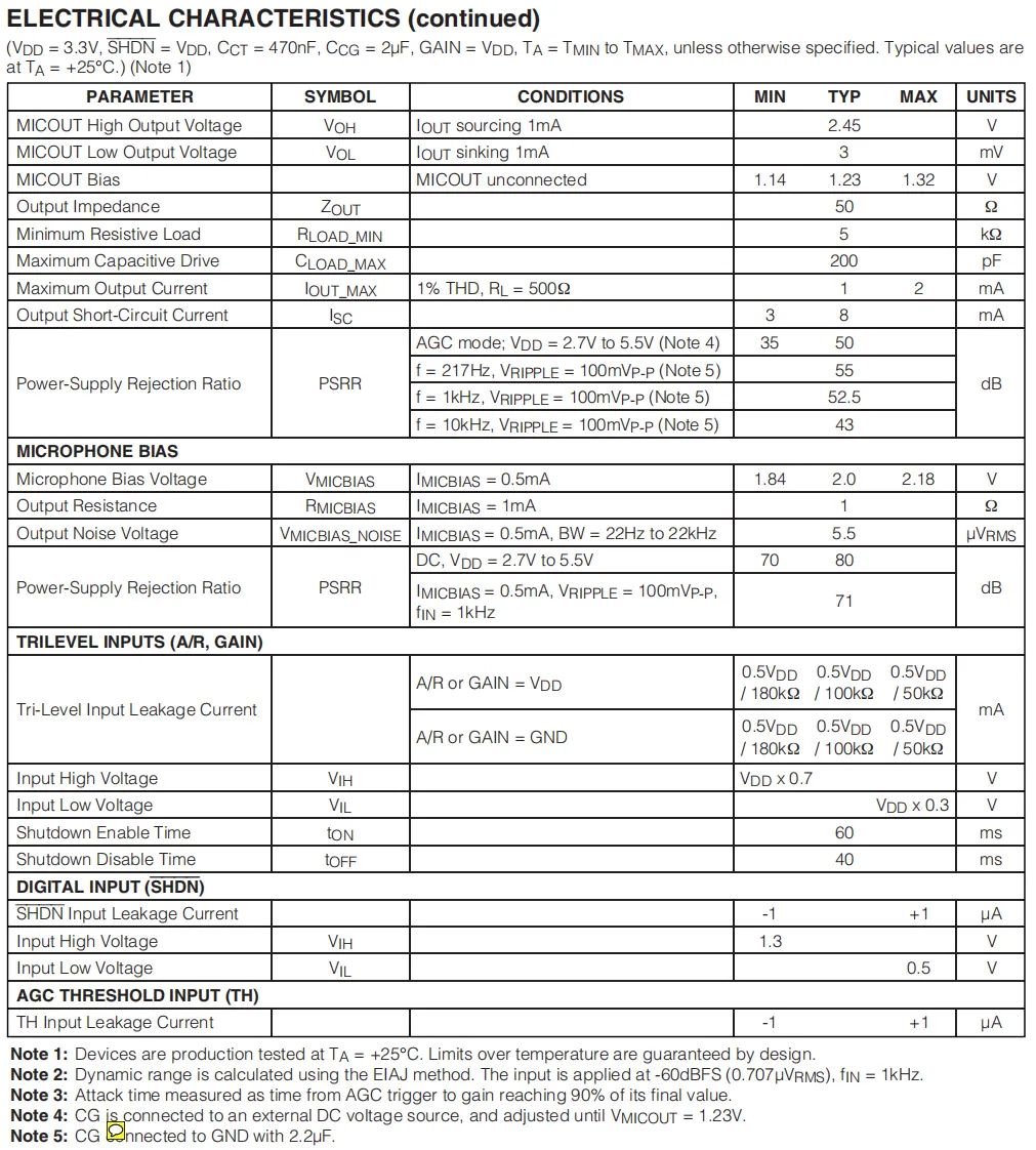
MICOUTCharacteristics: High output voltage (2.45V at 1mA sink current), low output voltage (43mV at 1mA source current), bias voltage 1.14V~1.32V (when unconnected), output impedance 50Ω, minimum resistive load 5kΩ, maximum capacitive drive 200pF, maximum output current 1mA~2mA (1%THD,RL= 500Ω), typical output short-circuit current 50mA (35mA~80mA inAGCmode), power supply rejection ratio (PSRR) 52.5dB~55dB across multiple frequencies.- Microphone Bias: Bias voltage 1.84V~2.18V (
IMICBIAS≤ 0.5mA), output resistance 1Ω(IMICBIAS= 1mA), output noise voltage 5.5μVRMS(IMICBIAS= 0.5mA, bandwidth 22Hz~22kHz), power supply rejection ratio 70dB~80dB (DCcondition) / 71dB (AC condition). - Three-level input (
A/R,GAIN): The input leakage current has corresponding specifications depending on the connection method, input high voltageVDD×0.7V, input low voltageVDD×0.3V, turn-on enable time 60ms, turn-off disable time 40ms. - Digital Input (
SHDN): Input leakage current -1μA to + 1μA, input high voltage 1.3V, input low voltage 0.5V. AGCThreshold Input (TH): Input leakage current: -1μA to + 1μA.
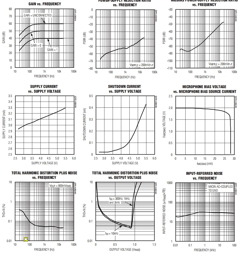
GAINvs.FREQUENCY: Shows the variation relationship of gain with frequency under different gain settings, reflecting the frequency response characteristics.POWER-SUPPLY REJECTION RATIOvs.FREQUENCY: shows the variation of power-supply rejection ratio with frequency, reflecting the chip's ability to suppress power supply noise.MICBIAS POWER-SUPPLY REJECTIONvs.FREQUENCY: Demonstrates the variation of the power supply rejection ratio of the microphone bias with frequency, reflecting the capability of the bias circuit to resist power supply noise.SUPPLY CURRENTvs.SUPPLY VOLTAGE: reflects the variation of supply current with supply voltage, and embodies the power consumption under different supply voltages.SHUTDOWN CURRENTvs.SUPPLY VOLTAGE: Illustrates the variation of current with supply voltage in shutdown mode, reflecting the current characteristics of the low-power shutdown state.Microphone Bias Voltagevs.Microphone Bias Source Current: Illustrates the variation of microphone bias voltage with the bias source current, reflecting the load characteristics of the bias circuit.TOTAL HARMONIC DISTORTION PLUS NOISEvs.FREQUENCY: Illustrates the variation of total harmonic distortion plus noise with frequency, reflecting the distortion and noise performance at different frequencies.TOTAL HARMONIC DISTORTION PLUS NOISEvs.OUTPUT VOLTAGE: Demonstrates the variation of total harmonic distortion plus noise with output voltage, reflecting the distortion and noise conditions at different output levels.INPUT-REFERRED NOISEvs.FREQUENCY: Reflects the variation of input-referred noise with frequency and characterizes the noise performance of the chip's input stage.
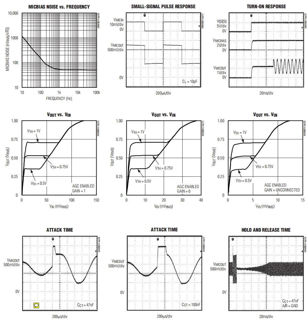
MICBIAS NOISE vs. FREQUENCY: Demonstrates the variation characteristic of microphone bias noise with frequency, and reflects the noise frequency distribution of the bias circuit.SMALL-SIGNAL PULSE RESPONSE: Presents the output response under small-signal pulse input, reflecting the small-signal dynamic response capability of the chip.TURN-ON RESPONSE: Demonstrates the signal response during the chip turn-on process, reflecting the dynamic behavior in the startup phase.Vout vs. Vin (GAIN= 1): shows the variation of output voltage with input voltage when the gain is set to 1, combiningAGCand threshold voltage characteristics.Vout vs. Vin (GAIN= 0): Demonstrates the variation of output voltage with input voltage when the gain is set to 0, reflecting the input-output relationship at this gain setting.Vout vs. Vin(GAINUnconnected): Shows the variation of output voltage with input voltage when the gain pin is unconnected, reflecting the characteristics under the default gain.ATTACK TIME(CCT= 47nF): Displays theCCTcapacitance at 47nFAGCstart-up time waveform, reflecting the gain start-up response speed under this capacitance.ATTACK TIME(CCT= 100nF): Displays theAGCstart-up time waveform when theCCTcapacitance is 100nF, reflecting the differences in start-up response under different capacitance values.HOLD AND RELEASE TIME: Displaysthe hold and release time characteristics of AGC, reflecting the process of gain hold and recovery.
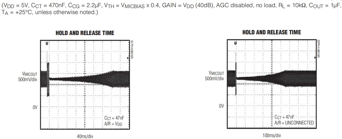
- Left figure: The "
HOLD AND RELEASE TIME" chart, with test conditions ofCCT= 47nF,A/R= VDD, shows the hold and release time waveforms ofAGCunder this configuration, reflecting the dynamic process of gain hold and recovery. - Right figure: The “
HOLD AND RELEASE TIME” chart, with test conditions ofCCT= 47nFandA/R= unconnected, demonstrates the hold and release time waveforms ofAGCunder this configuration, reflecting the impact of differentA/Rsettings on the hold and release characteristics.
2.5 Reference Circuit
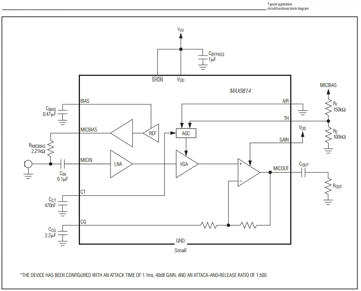
- Power Supply and Shutdown:
VDDis the power supply input (2.7V~5.5V), with a shunt1μFcapacitor for filtering;SHDNpin is left unconnected, and the chip operates in normal mode. - Microphone Bias and Input:
R_MICBIAS(2.21 kΩ) andC_IN(0.1 μF) form an input coupling and bias circuit to supply a bias voltage for the electret microphone;C_BIAS(0.47 μF) is a bias bypass capacitor for noise reduction. - Amplification and AGC Link: After the microphone signal is input via
MICIN, it passes throughLNA(Low Noise Amplifier),VGA(Variable Gain Amplifier), and output amplifier in sequence, and is finally output fromMICOUT;AGC(Automatic Gain Control) realizes dynamic gain adjustment through the pin configuration ofCT(connected to a470nFcapacitor),CG(connected to a2.2μFcapacitor),A/RandTH. - AGC and Gain Configuration:
A/Ris grounded,THsets the AGC threshold via resistor voltage division;GAINis connected toVDDto set the gain to 40dB; after circuit configuration, the startup time is 1.1ms, and the attack-release ratio is 1:500. - Output Coupling:
C_OUTis the output coupling capacitor, andR_OUTis the load resistor, which realizes the connection between the signal output and the subsequent stage circuit.
2.6 Chip Configuration
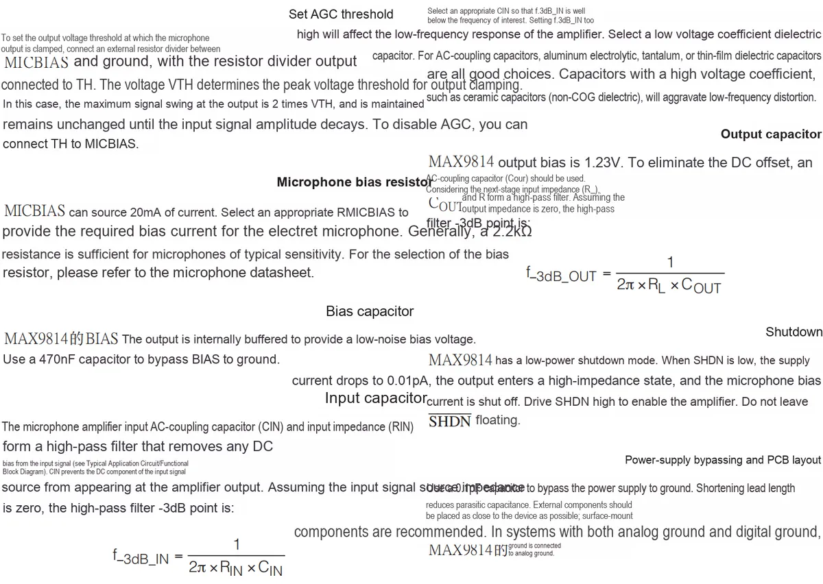
- Set
AGCthreshold: adjustTHpin's external resistance voltage divider or connection mode to change the voltage threshold of output clamping. - Microphone Bias Resistor: Select bias resistors with different resistance values to adjust the bias current of the electret microphone.
- Bias Capacitor: The 470nF bypass capacitor affects
BIASthe noise performance of the output. - Input Capacitance: It forms a high-pass filter together with the input impedance, affecting the low-frequency response.
- Output Capacitor: It forms a high-pass filter together with the load resistor to eliminate DC offset.
- Shutdown Configuration:
The SHDNpin level (low/high) controls the chip power consumption, output status, and microphone bias current. - Power Bypassing and
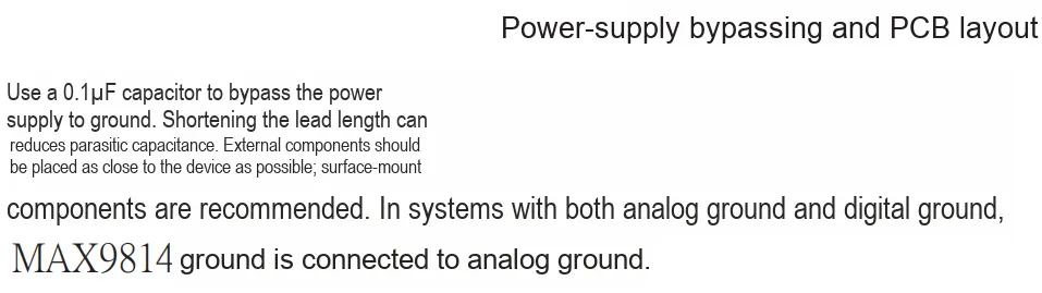
PCBLayout: Power bypass capacitors and layout schemes affect parasitic capacitance, noise and signal integrity.
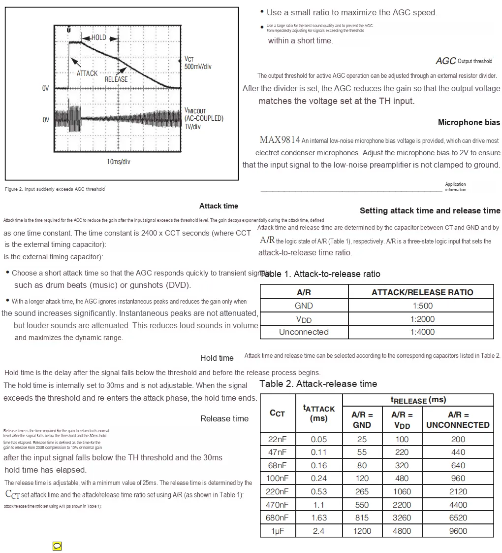
Modifying the connection mode of the A/R pins (connecting to GND, VDD or leaving unconnected) will alter the attack/release ratio of AGC; adjusting the capacitance of the CCT capacitor will change the attack time and release time of AGC. The two factors jointly affect the dynamic response characteristics of AGC for audio signal gain adjustment, such as the speed of gain variation and amplitude control, etc.
2.7 Communication Interfaces and Related Protocols
None.
2.8 PCB Routing Precautions
III. Instructions for Circuit Engineering and Module Usage
3.1 Circuit Source Engineering
To obtain the source code of the circuit, please follow the official account [Freak Embedded]
3.2 Module Usage Instructions
The schematic diagram of this module is shown below:
SCH_MAX9814-Based_Electret_Condenser_Microphone_Module_v1.0_2025-11-24.pdf 2.4 MB
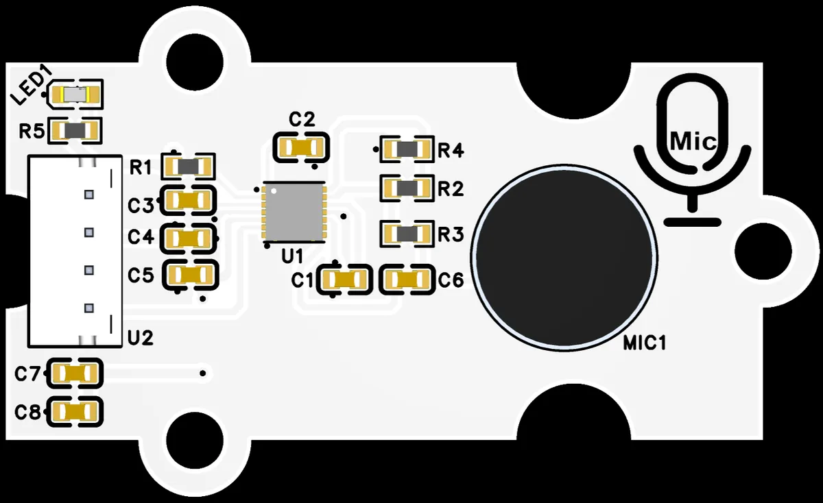
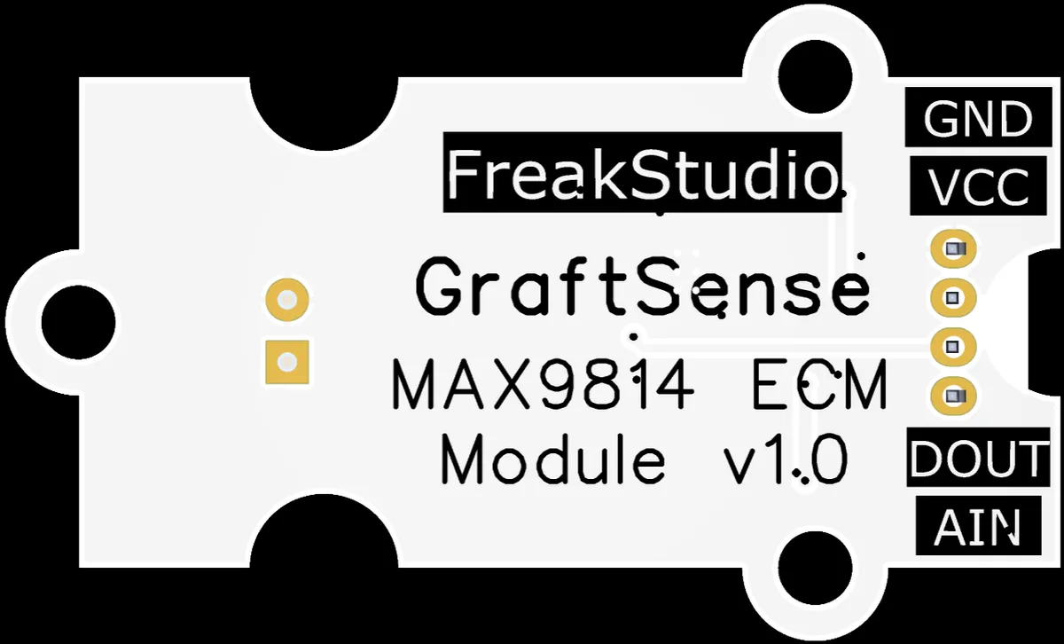
This module provides gain control DOUT interface and analog output AIN interface: DOUT is connected to the MCU 's GPIO, and the gain of MAX9814 (e. g., switching between 40dB/50dB/60dB and other gain levels) can be configured by the high/low level output from the MCU;AIN is connected to the MCU ' s ADC, which is used to collect the analog audio signal output by the module.
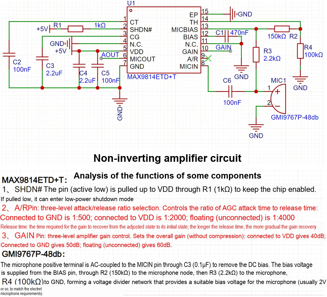
The schematic diagram is explained as follows:
- Power Supply and Filtering: The module is powered by + 5V,
C2(100nF),C3(2.2μF),C4(2.2μF), andC5(100nF) form a power filter circuit that suppresses power supply noise to ensure stable operation of the chip. MAX9814Core Functions:U1is theMAX9814microphone amplifier chip. TheSHDN#pin is pulled up to + 5V viaR1(1kΩ), placing the chip in normal operation mode;MICINpin couples the electret microphoneMIC1throughC6(100nF) to realize audio input;BIASpin is bypassed to ground viaC1(470nF) to provide low-noise bias;MICBIASpin is divided viaR2(150kΩ) andR4(100kΩ) to supply a proper bias voltage for the microphone.- Gain and Interfaces:
The configuration of the GAINpins determines the amplification gain;the MICOUTpin serves as an analog output (AINinterface) to connect to theMCU'sADC;The DOUTinterface enables flexible gain adjustment by controlling gain-related pins (such asGAINandA/R), adapting to the requirements of different audio acquisition scenarios.
3.3 Application Experiment
Here, we use the GraftPort-RP2040 development board for testing, and connect the electret condenser microphone module based on MAX9814 to communicate with the main controller via the AIN interface.
Here, we first use the HY2.0-4P connection cable to connect the module to the GraftPort-RP2040 development board's AIN0 interface:
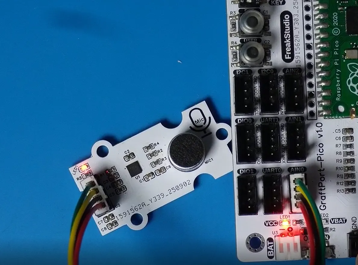
The module connections are shown in the following table:
Development Board Pins | Module Pins | Description |
Pin 26 |
| Microphone analog signal input pin |
Pin 19 |
| Microphone amplifier chip gain control digital pin |
Here, we need to search for relevant driver packages on uPyPI: https://upypi.net/zh/
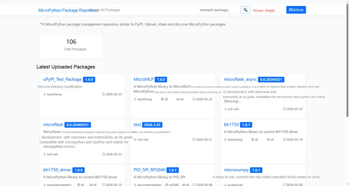
Enter max9814_mic_driver to search, and the following will be displayed:

Click to copy the local installation command:
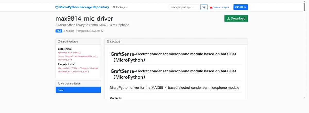
Here, we can use the mip tool to import module driver library code. Below are the usage commands for the mpremote tool:
mpremote mip install github:FreakStudioCN/GraftSense-Drivers-MicroPython/sensors/max9814_mic_driverImport the MAX9814-based electret condenser microphone module - MicroPython driver code, then copy the following main.py code into our project:
# Python env   : MicroPython v1.23.0
# -*- coding: utf-8 -*-
# @Time    : 2025/8/28
# @Author  : 缪贵成
# @File    : main.py
# @Description : MAX9814 microphone driver simple test

# ======================================== Import Modules =========================================

import time
from machine import Pin, ADC
from max9814_mic import MAX9814Mic

# ======================================== Global Variables ============================================

# ======================================== Functions ============================================

def get_formatted_time() -> str:
    """
    Get the formatted time string (HH:MM:SS).

    Returns:
        str: The formatted time string.

    Notes:
        Use time.localtime() to get the local time.
        Suitable for log printing.

    ==========================================

    Get formatted time string (HH:MM:SS).

    Returns:
        str: Formatted time string.

    Notes:
        Uses time.localtime().
        Useful for log printing.
    """
    # Get the current local time tuple
    t = time.localtime()
    # Format the output as hours, minutes, and seconds
    return "{:02d}:{:02d}:{:02d}".format(t[3], t[4], t[5])

def test_basic_reading() -> None:
    """
    Basic read test: continuously print the raw value, normalized value, and voltage.

    Raises:
        KeyboardInterrupt: Exit when interrupted by the user.

    Notes:
        GP26 (ADC0) is used by default.
        Runs in a loop for about 10 seconds.
    ==========================================

    Basic reading test: print raw, normalized, and voltage.

    Raises:
        KeyboardInterrupt: On user interrupt.

    Notes:
        Uses GP26 (ADC0).
        Runs ~10 seconds.
    """
    # Initialization configuration
    time.sleep(3)
    print("FreakStudio:max9814_mic_driver test start")
    print("=== Basic Reading Test ===")
    # GP26 = ADC0 input
    adc = ADC(26)

    # Initialize the microphone instance
    mic = MAX9814Mic(adc=adc)

    print("Microphone initialized on ADC0 (GP26)")
    # Print the module status
    print("State:", mic.get_state())
    print("Reading values for ~10 seconds...")

    try:
        # Once every 0.1 seconds, 10 seconds in total
        for i in range(100):
            # Raw ADC value
            raw_value = mic.read()
            # Normalized value (0–1)
            normalized = mic.read_normalized()
            # Voltage value (V)
            voltage = mic.read_voltage()
            print("[{}] Raw:{:5d} | Norm:{:.3f} | Volt:{:.3f}V".format(
                get_formatted_time(), raw_value, normalized, voltage
            ))
            # Delay 0.5 seconds
            time.sleep(0.5)
    except KeyboardInterrupt:
        print("\n[{}] Basic test interrupted".format(get_formatted_time()))

def test_with_gain_control() -> None:
    """
    Gain control test: switch between low-gain and high-gain modes and sample.

    Raises:
        KeyboardInterrupt: Exit when interrupted by the user.

    Notes:
        GP15 is used to control the gain.
        Low-gain mode runs first, then switches to high-gain mode.

    ==========================================

    Gain control test: switch low/high gain modes.

    Raises:
        KeyboardInterrupt: On user interrupt.

    Notes:
        GP15 controls gain pin.
        Runs low gain first, then high gain.
    """
    # Initialization configuration
    time.sleep(3)
    print("FreakStudio:max9814_mic_driver test start")
    print("=== Basic Reading Test ===")
    # GP26 = ADC0 input
    adc = ADC(26)

    # Initialize GP6 as the gain control pin
    gain_pin = Pin(6, Pin.OUT)
    mic = MAX9814Mic(adc=adc, gain_pin=gain_pin)
    try:
        # Low-gain mode
        print("=== LOW GAIN mode ===")
        mic.set_gain(False)  # Set to low gain
        print("State:", mic.get_state())
        for i in range(50):
            print("[LOW] {:5d}".format(mic.read()), end=" ")
            if (i + 1) % 5 == 0:  # New line every 5 values
                print()
            time.sleep(0.6)

        # High-gain mode
        print("\n=== HIGH GAIN mode ===")
        mic.set_gain(True)  # Set to high gain
        print("State:", mic.get_state())
        for i in range(50):
            print("[HIGH]{:5d}".format(mic.read()), end=" ")
            if (i + 1) % 5 == 0:
                print()
            time.sleep(0.6)

    except KeyboardInterrupt:
        print("\n[{}] Gain test interrupted".format(get_formatted_time()))

def test_sound_detection() -> None:
    """
    Sound detection test: determine whether there is sound in the environment based on a threshold.
    Raises:
        KeyboardInterrupt: Exit when interrupted by the user.
    Notes:
        Automatically calibrate the ambient noise baseline.
        Threshold = baseline + 5000.
        Detection results are printed in real time.

    ==========================================

    Sound detection test: detect sound above threshold.

    Raises:
        KeyboardInterrupt: On user interrupt.

    Notes:
        Calibrates baseline automatically.
        Threshold = baseline + 5000.
        Prints detection results.
    """
    # Initialization configuration
    time.sleep(3)
    print("FreakStudio:max9814_mic_driver test start")
    print("=== Basic Reading Test ===")
    # GP26 = ADC0 input
    adc = ADC(26)

    # Initialize the microphone instance
    mic = MAX9814Mic(adc=adc)
    print("Calibrating baseline noise level...")
    # Get the average ambient noise level
    baseline = mic.calibrate_baseline(samples=200)
    # Set the threshold
    threshold = baseline + 5000
    print("Baseline:", baseline)
    print("Threshold:", threshold)
    print("Make some noise near the mic! (Ctrl+C to stop)")

    try:
        # Counter, records silent cycles
        silent_count = 0
        while True:
            # Current reading
            current_value = mic.read()
            # Check whether the threshold is exceeded
            is_sound = mic.detect_sound_level(threshold=threshold, samples=10)
            if is_sound:
                # Get the peak value
                peak = mic.get_peak_reading(samples=20)
                print("[{}] SOUND! Current:{} Peak:{}".format(
                    get_formatted_time(), current_value, peak
                ))
                silent_count = 0
            else:
                silent_count += 1
                # Print the status once every 50 quiet detections
                if silent_count % 50 == 0:
                    print("[{}] Silent... Current:{} (Th:{})".format(
                        get_formatted_time(), current_value, threshold
                    ))
            time.sleep(0.6)
    except KeyboardInterrupt:
        print("\n[{}] Detection stopped".format(get_formatted_time()))

# ======================================== Custom Classes =============================================

# ======================================== Initialization configuration ===========================================

# ========================================  Main Program  ============================================

print("MAX9814 Microphone Simplified Test Suite")
print("Choose test mode by editing code:")
print("1. Basic reading test")
print("2. Gain control test")
print("3. Sound detection test")
time.sleep(5)

try:
    # Modify the function call below to select the test mode
    # test_basic_reading()
    # test_with_gain_control()
    test_sound_detection()
except Exception as e:
    print("Error:", e)
To flash the code, open a terminal and use the mpremote tool to connect to the main controller; the output is as follows:
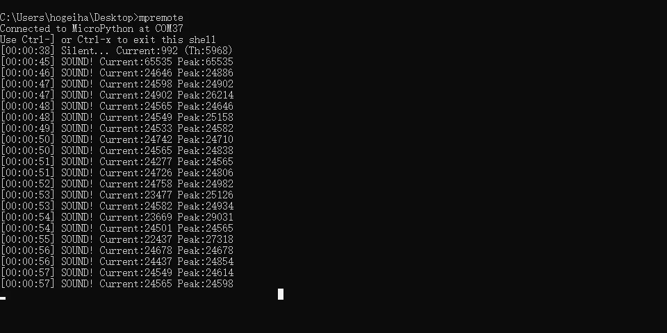
Next, we need to get close to the microphone to speak or play music, and you can see that the corresponding volume value and peak value change:
IV. Drivers
max9814_mic_driver.zip 17 KB
5. BOM & Recommended Alternative Parts
None.
VI. Revision History
Document Version | Date of Revision | Modifier | Revised Content |
v1.0 | 2025-11-24 | Li Zisheng | Initialize the document The BOM sheet has not been finally checked, the driver has not been re-verified, and the 3.3 application experiment Not yet specified. |
v1.1 | 2025-12-29 | Li Zisheng | Added application experiments and production files |
v1.2 | 2025-12-31 | Xin Ruili | Create an open version of the document based on the internal document version v1.1. |
v1.3 | 2026-03-29 | Xin Ruili | Modified the application experiment section |
VII. Relevant Materials
7.1 Chip Datasheet
C41714_Audio_Power_Amplifier_MAX9814ETD+T_Datasheet_WJ105517.PDF 635 KB
max9814_cn.pdf 1.4 MB
7.2 Unique Icons for PCB Silk Screen