Contents
- I. Module Introduction
- II. Introduction to Main Chips
- 2.1 Chip Overview
- 2.2 Pin Definition
- 2.3 Functional Block Diagram
- 2.4 Performance Parameters
- 2.5 Reference Circuit
- 2.6 Chip Configuration
- 2.7 Communication Interfaces and Related Protocols
- 2.8 PCB Routing Notes
- III. Circuit Engineering
- 3.1 Circuit Source Engineering
- 3.2 Module Usage Instructions
- 3.3 Application Experiment
- IV. Drivers
- 5. BOM & Recommended Alternative Parts
- 6. Revision History
- VII. Relevant Materials
- 7.1 Chip Datasheet
- 7.2 Unique Icons for PCB Silk Screen
I. Module Introduction
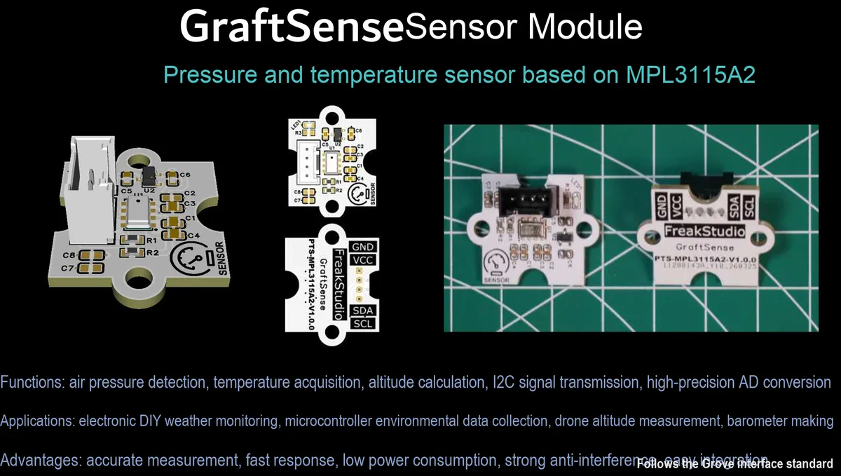
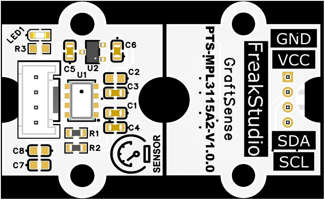
Pressure and Temperature Sensor Module Based on MPL3115A2, adopting the MPL3115A2 chip solution, is a high-precision MEMS barometric pressure sensor with a built-in 24-bit ADC, which can directly output compensated barometric pressure and temperature data; it features a barometric pressure measurement range of 20~110 kPa with a resolution of 1.5 Pa (equivalent to an altitude resolution of approximately 0.3 m), and a temperature measurement range of -40℃~+ 85℃ with an accuracy of ±1℃;The module integrates LDO voltage regulation, power filtering and I²C pull-up circuits, and is equipped with a power indicator. The fixed address of the I²C interface is 0x60, supporting a maximum communication rate of 400 kHz. The built-in FIFO buffer can store up to 32 sets of data, and is compatible with 3.3V level MCUs. It is suitable for meteorological monitoring, altimeters, portable environmental detection and low-power IoT scenarios.
II. Introduction to Main Chips
MPL3115A2 is a high-precision 24-bit MEMS barometric pressure and temperature sensor, I²C interface with a fixed address of 0x60, a pressure measurement range of 20~110 kPa (resolution 1.5 Pa, equivalent height resolution 0.3 m), built-in FIFO and compensation algorithm, suitable for barometric pressure / altitude / temperature detection scenarios.
2.1 Chip Overview
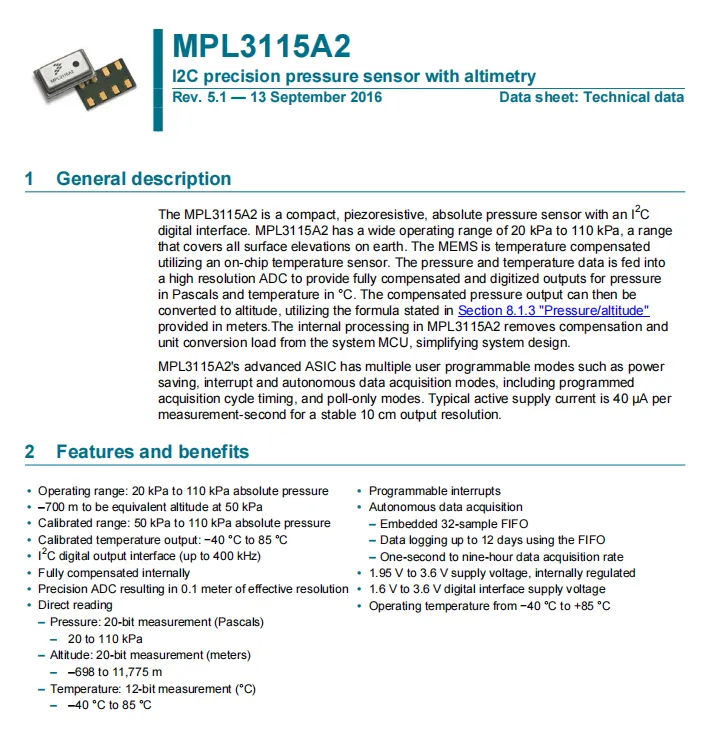
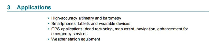
MPL3115A2 is a compact piezoresistive absolute pressure sensor that features the I²C digital interface (max. 400 kHz), built-in temperature compensation and high-precision ADC, and can directly output compensated barometric pressure (20~110 kPa, equivalent altitude -698~11775 m, resolution 0.1 m) and temperature (-40~85℃) data, reducing the computational load on the MCU;It supports programmable modes such as low power consumption, interrupt, and autonomous sampling, with a built-in 32-sample FIFO, a supply voltage of 1.95~3.6 V, and is suitable for scenarios including high-precision pressure/altitude measurement, wearable devices, GPS assisted navigation, and weather stations.
2.2 Pin Definition
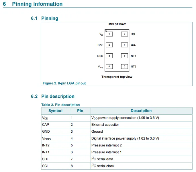
MPL3115A2 chip adopts an 8-pin LGA package with clearly defined pin functions, including main power supply VDD (1.95~3.6 V), digital interface power supply VDDIO (1.62~3.6 V), ground GND, external capacitor pin CAP, two pressure interrupt pins INT1 / INT2, and I²C communication pins SDL (serial data) and SCL (serial clock).
2.3 Functional Block Diagram
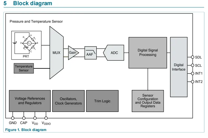
MPL3115A2 has a core signal chain consisting of a piezoresistive pressure sensor (Wheatstone bridge PRT) + an on-chip temperature sensor that acquires raw signals; after being switched via a multiplexer (MUX), the signals are sent to a programmable gain amplifier (Gain) for amplification, then filtered by an anti-aliasing filter (AAF), and finally converted into digital values by a high-precision ADC;The Digital Signal Processing module combines temperature data to complete internal compensation and unit conversion, with the results stored in configuration and data registers, and finally output through the digital interface (I²C communication pins SDL / SCL), while supporting INT1 / INT2 interrupt triggering; the chip also integrates auxiliary circuits such as voltage reference and regulation, clock oscillation, and trimming logic, and is powered and configured with external capacitors via the GND, CAP, VDD, VDDIO pins to ensure stable operation.
2.4 Performance Parameters
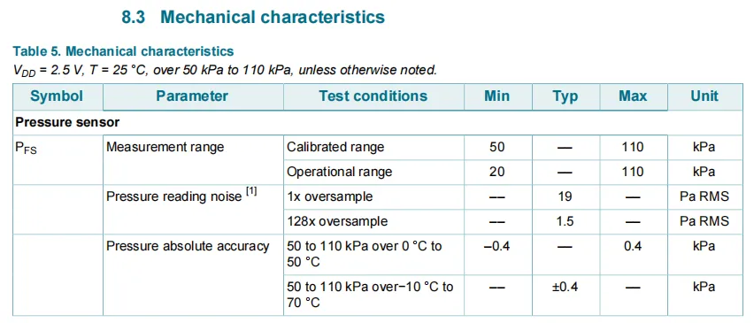
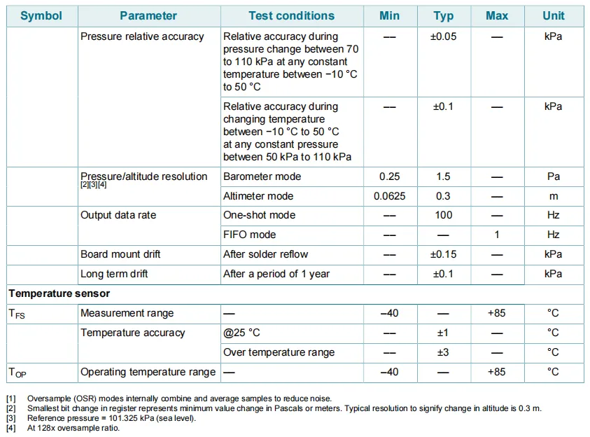
MPL3115A2 under VDD = 2.5 V and 25°C conditions:
- Pressure sensor: operating range 20~110 kPa, calibrated range 50~110 kPa; noise decreases with oversampling rate (19 Pa at 1x
RMS, 1.5 Pa at 128xRMS), absolute accuracy ±0.4 kPa, relative accuracy ±0.05~±0.1 kPa; barometric pressure resolution 0.25~1.5 Pa, altitude resolution 0.0625~0.3 m; board-level drift ±0.15 kPa, long-term drift ±0.1 kPa. - Temperature sensor: Measurement range: -40 to + 85°C, accuracy ±1°C at 25°C, accuracy ±3°C over the entire temperature range, and its operating temperature range is consistent with that of the pressure sensor.
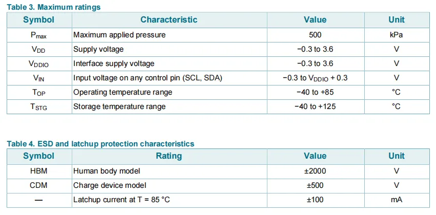
MPL3115A2 Absolute Maximum Ratings and ESD / Latch-Up Protection Characteristics Table:
- Absolute Maximum Ratings: Maximum withstand pressure 500 kPa, the main power supply
VDDand interface power supplyVDDIOboth have a range of -0.3 to 3.6 V, the input voltage range of control pins is -0.3 toVDDIO+ 0.3 V, operating temperature -40 to + 85℃, storage temperature -40 to + 125℃. ESDand Latch-Up Protection: Human Body Model (HBM) protection up to ±2000 V, Charged Device Model (CDM) protection up to ±500 V, latch-up current of ±100 mA at 85°C.
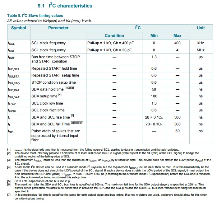
MPL3115A2 at the specified level reference, its SCL clock frequency has a maximum value of 400 kHz with a 1kΩ pull-up and 400 pF load, and can reach 4 MHz with a 20 pF load;Bus idle time, repeated START / STOP setup and hold time, SDA data setup and hold time, and SCL high and low level duration all have clear minimum requirements. The rise/fall times of SDA and SCL vary with the bus capacitance Cᵦ and do not exceed 300ns. Meanwhile, the internal input filter can suppress pulse interference with a width not exceeding 50ns, which fully meets the timing specifications of standard and fast I²C communication.
2.5 Reference Circuit
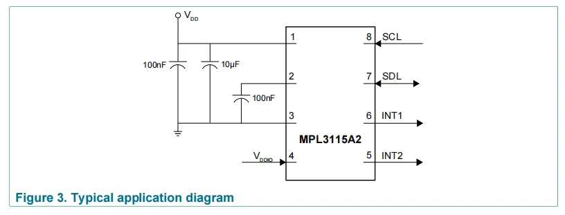
MPL3115A2 chip main power supply VDD (Pin 1) is grounded via filtering with 100nF and 10μF capacitors;CAP pin (2) is connected to a 100nF capacitor leading to GND (Pin 3), and the digital interface power supply VDDIO is connected to Pin 4;I²C communication pins SCL (8) and SDL (7) are connected to the main control MCU, while INT1 (6) and INT2 (5) are interrupt output pins. The overall circuit is simple and can directly realize pressure/temperature Data Acquisition.
2.6 Chip Configuration
None.
2.7 Communication Interfaces and Related Protocols
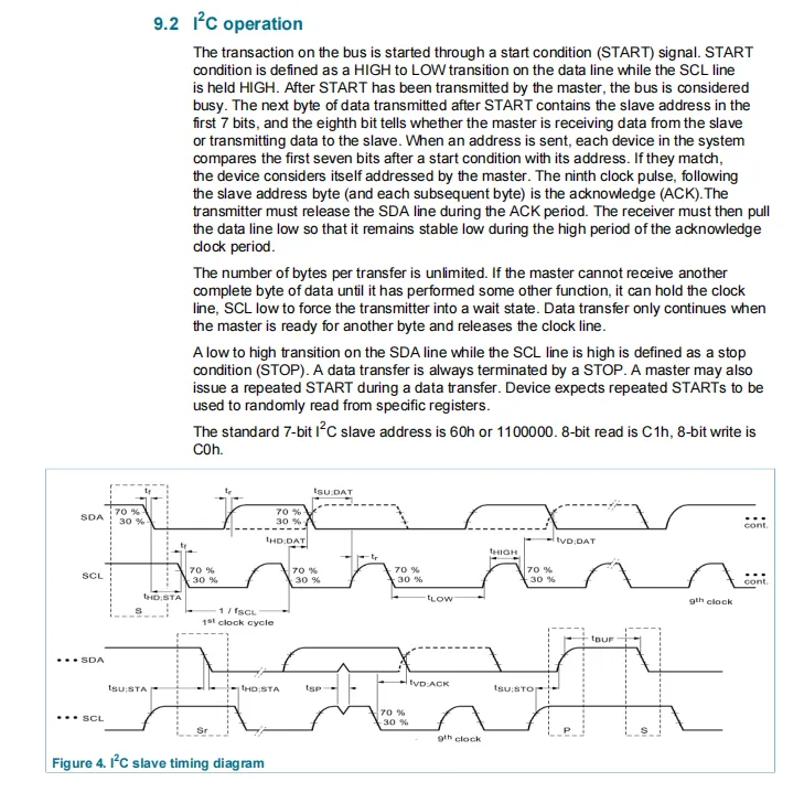
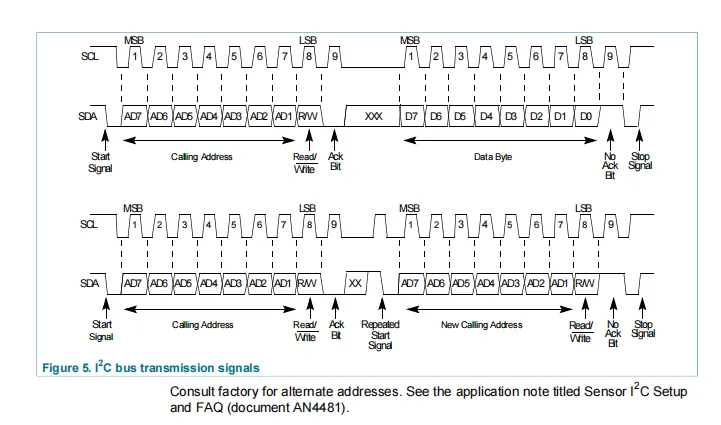
MPL3115A2 adopts standard 7-bit I²C slave communication with the address 0x60 (8-bit read 0xC1, write 0xC0). The communication is initiated by the host via a START condition (a falling edge on SDA when SCL is high), followed by the transmission of a 7-bit slave address plus a 1-bit read/write control bit, with the 9th bit being an ACK acknowledge bit. There is no limit to the number of bytes transmitted; the host can pull the SCL clock low to implement waiting. The transmission ends with a STOP condition (a rising edge on SDA when SCL is high), and a repeated START can also be inserted during transmission to randomly read registers. The Sequence Diagram clearly illustrates the complete communication processes including START / STOP, data setup and hold, acknowledge, and repeated START.
2.8 PCB Routing Notes
None.
III. Circuit Engineering
3.1 Circuit Source Engineering
To obtain the circuit source project, please follow the official account [Freak Embedded].
3.2 Module Usage Instructions
The schematic diagram of this module is shown below:
SCH_Pressure and Temperature Sensor Based on MPL3115A2-V1.0.0_2026-03-30.pdf 2.2 MB
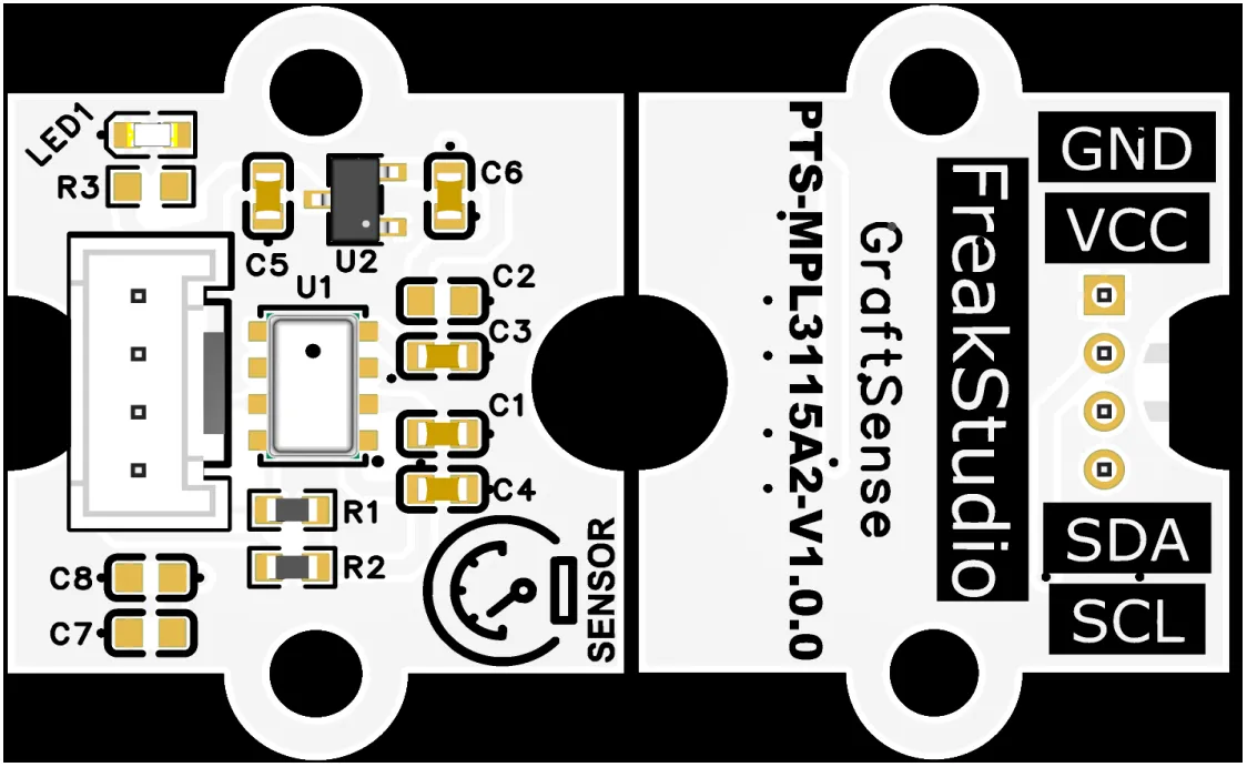
This module provides an I²C communication interface: it supports standard and fast I²C communication rates up to 400 kHz, with a fixed interface address of 0x60, and is compatible with 3.3V level MCUs;The module integrates LDO voltage regulation, power filtering and I²C pull-up circuits, and is equipped with a power indicator. It can output high-precision barometric pressure (20~110 kPa, resolution 1.5 Pa, equivalent altitude resolution of approximately 0.3 m) and temperature (-40℃~+ 85℃, accuracy ±1℃) data, with a built-in 32-sample FIFO buffer. It is suitable for meteorological monitoring, altimeters, portable environmental detection and low-power IoT scenarios, providing reliable environmental parameter acquisition and interaction capabilities for the system.
3.3 Application Experiment
Here, we use the GraftPort-RP2040 development board for testing, and the MPL3115A2-based pressure and temperature sensor communicates with the main controller via the I2C interface.
Here, we first use the HY2.0-4P connection cable to connect the module to the GraftPort-RP2040 development board's I2C0 interface:
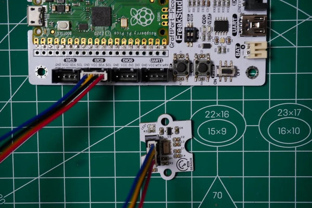
The module connections are shown in the following table:
Development Board Pins | Module Pins | Description |
Pin 4 |
|
|
Pin 5 |
|
|
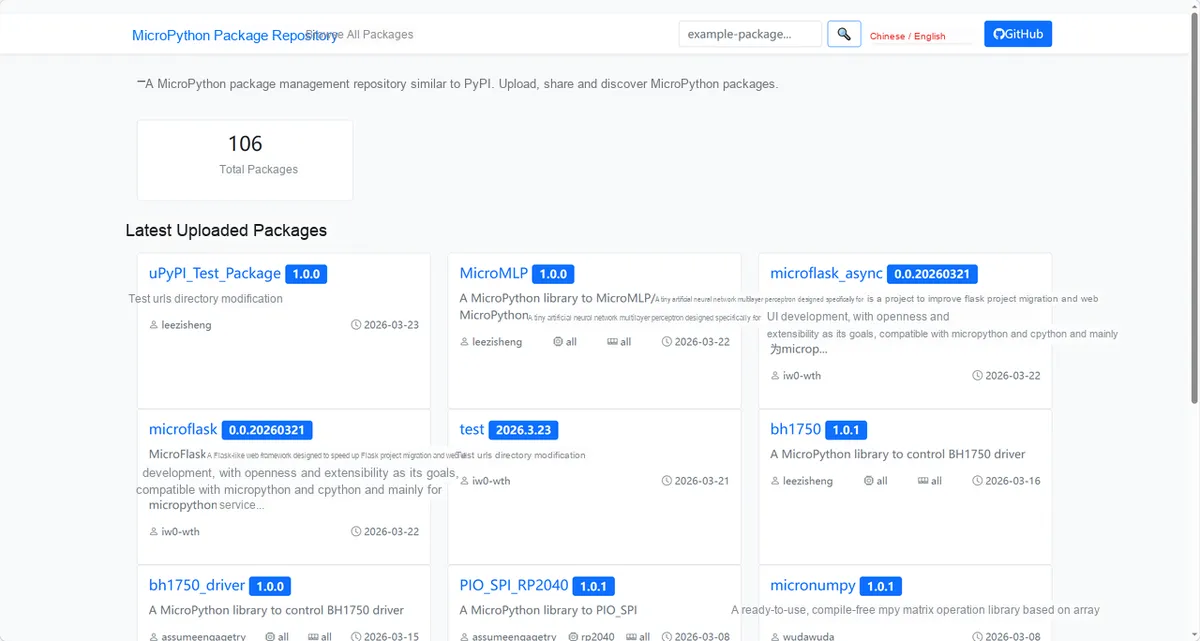
Here, we need to search for the relevant driver packages on uPyPI: https://upypi.net/zh/
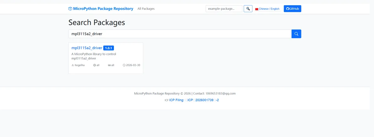
Enter mpl3115a2_driver to search, and the following will be displayed:
Click to copy the local installation command:
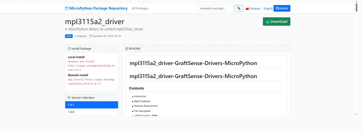
Import the module driver library code via the mip tool. Below are the usage commands for the mpremote tool:
mpremote mip install https://upypi.net/pkgs/mpl3115a2_driver/1.0.0After importing the pressure and temperature sensor based on MPL3115A2 - MicroPython driver code, copy the following main.py code into our project:
# Python env   : MicroPython v1.23.0
# -*- coding: utf-8 -*-
# @Time    : 2026/3/12 4:00 PM
# @Author  : PinsonJonas
# @File    : main.py
# @Description : MPL3115A2 sensor test: read pressure, altitude and temperature; exception handling demo

# ======================================== Import Modules =========================================

import time
from machine import I2C, Pin
from mpl3115a2 import MPL3115A2, MPL3115A2exception

# ======================================== Global Variables ============================================

# I2C configuration (Raspberry Pi Pico specific)
I2C_BUS = 0  # I2C bus number of the Pico
I2C_SCL_PIN = 5  # I2C clock pin
I2C_SDA_PIN = 4  # I2C data pin
I2C_FREQ = 400000  # 400kHz fast I2C frequency supported by the MPL3115A2
# MPL3115A2 sensor parameters
MPL3115A2_ADDR = 0x60  # Default I2C address of the sensor
SAMPLING_INTERVAL = 0.6  # Minimum sampling interval (must be greater than the sensor's 512ms sampling time)
LONG_MONITOR_DURATION = 10  # Total duration of long-term monitoring (seconds)
LONG_MONITOR_INTERVAL = 2  # Sampling interval of long-term monitoring (seconds)

# ======================================== Functions ============================================


def init_i2c():
    """
    Initialize the I2C bus (adapted to Raspberry Pi Pico hardware)
    Initialize I2C bus (adapted for Raspberry Pi Pico hardware)

    Args:
        None

    Returns:
        I2C: Returns the I2C object on successful initialization; returns None on failure
        I2C: Return I2C object if initialization succeeds; return None if fails

    Notes:
        1. Only supports the I2C0 bus of the Raspberry Pi Pico; to use I2C1, change the pins (SCL=15, SDA=14)
        2. During initialization, the devices on the I2C bus are scanned and the MPL3115A2 default address is checked for
        1. Only adapted for I2C0 bus of Raspberry Pi Pico, modify pins (SCL=15, SDA=14) if using I2C1
        2. Scan I2C bus devices during initialization and check if MPL3115A2 default address exists
    """
    try:
        # Initialize the I2C0 bus of the Pico
        i2c = I2C(I2C_BUS, scl=Pin(I2C_SCL_PIN), sda=Pin(I2C_SDA_PIN), freq=I2C_FREQ)
        detected_devices = [hex(addr) for addr in i2c.scan()]
        print(f"I2C initialization successful, detected device addresses: {', '.join(detected_devices)}")

        # Check whether the MPL3115A2 sensor is present
        if hex(MPL3115A2_ADDR) not in detected_devices:
            print("Warning: MPL3115A2 sensor not detected (default address 0x60)")
            return None
        return i2c
    except Exception as e:
        print(f"I2C initialization failed: {e}")
        return None


def print_separator(title):
    """
    Print a separator to improve output readability
    Print separator to optimize output readability

    Args:
        title (str): Separator title / demo module name
        title (str): Separator title / demonstration module name

    Returns:
        None

    Notes:
        The output is a separator line made of 65 equals signs, with the given title text shown in the middle
        Output format is a separator line composed of 65 equal signs with the incoming title text in the middle
    """
    print("\n" + "=" * 65)
    print(f"=== {title}")
    print("=" * 65)


def safe_measure(func, desc="measurement"):
    """
    Safely execute a measurement function, catch various exceptions and return the result status
    Safely execute measurement function, catch all types of exceptions and return result status

    Args:
        func (function): The measurement function to execute (e.g., mpl.pressure/mpl.altitude/mpl.temperature)
        func (function): Measurement function to execute (e.g. mpl.pressure/mpl.altitude/mpl.temperature)
        desc (str): Description text of the measurement operation, used in exception messages (default: measurement)
        desc (str): Measurement operation description text for exception prompt (default: measurement)

    Returns:
        tuple: (measurement result, execution status)
               - Execution succeeded: (measured value, True)
               - Execution failed: (None, False)
        tuple: (measurement result, execution status)
               - Success: (measurement value, True)
               - Failure: (None, False)

    Notes:
        1. Catches MPL3115A2 sensor-specific exceptions, I2C communication exceptions and generic exceptions
        2. All exception messages are output in English to make debugging and locating problems easier
        1. Catch MPL3115A2 sensor-specific exceptions, I2C communication exceptions, and general exceptions
        2. All exception information is output in English for easy debugging and problem location
    """
    try:
        result = func()
        return result, True
    except MPL3115A2exception as e:
        print(f"   {desc} failed - sensor exception: {e}")
    except OSError as e:
        if "EIO" in str(e):
            print(f"   {desc} failed - I2C communication error(Errno 5): {e}")
        else:
            print(f"   {desc} failed - I2C error: {e}")
    except Exception as e:
        print(f"   {desc} failed - unknown error: {e}")
    return None, False


# ======================================== Custom Classes ============================================

# ======================================== Initialization configuration ===========================================

time.sleep(3)
print("FreakStudio: MPL3115A2 sensor test - read pressure/altitude/temperature with exception handling")
# Initialize the I2C bus
i2c = init_i2c()
if not i2c:
    print("I2C initialization failed, program exit")
    raise SystemExit(1)

# ========================================  Main Program  ============================================

# 1. Barometer mode function demo
print_separator("1. Pressure mode demonstration")
try:
    # Initialize the pressure mode sensor object
    mpl_pressure = MPL3115A2(i2c, mode=MPL3115A2.PRESSURE)
    print("   MPL3115A2 pressure mode initialized successfully")

    # 5 consecutive pressure + temperature measurements
    print("\n   5 consecutive pressure + temperature measurements:")
    for i in range(5):
        pressure, p_ok = safe_measure(mpl_pressure.pressure, "pressure reading")
        temp, t_ok = safe_measure(mpl_pressure.temperature, "temperature reading")

        if p_ok and t_ok:
            pressure_kpa = pressure / 4000.0  # Convert to kPa (raw value resolution 0.25Pa)
            print(f"     Measurement {i+1} - Pressure: {pressure_kpa:.2f} kPa | Temperature: {temp:.2f} °C")
        time.sleep(SAMPLING_INTERVAL)

    # Test error scenario: read altitude in pressure mode (an exception is expected)
    print("\n   Test error scenario: Read altitude in pressure mode (expected exception):")
    alt, a_ok = safe_measure(mpl_pressure.altitude, "altitude reading")

except MPL3115A2exception as e:
    print(f"   Pressure mode initialization failed: {e}")
except Exception as e:
    print(f"   Pressure mode operation failed: {e}")

# 2. Altitude mode function demo
print_separator("2. Altitude mode demonstration")
try:
    # Initialize the altitude mode sensor object
    mpl_altitude = MPL3115A2(i2c, mode=MPL3115A2.ALTITUDE)
    print("   MPL3115A2 altitude mode initialized successfully")

    # 5 consecutive altitude + temperature measurements
    print("\n   5 consecutive altitude + temperature measurements:")
    for i in range(5):
        altitude, a_ok = safe_measure(mpl_altitude.altitude, "altitude reading")
        temp, t_ok = safe_measure(mpl_altitude.temperature, "temperature reading")

        if a_ok and t_ok:
            print(f"     Measurement {i+1} - Altitude: {altitude:.2f} m | Temperature: {temp:.2f} °C")
        time.sleep(SAMPLING_INTERVAL)

    # Test error scenario: read pressure in altitude mode (an exception is expected)
    print("\n   Test error scenario: Read pressure in altitude mode (expected exception):")
    press, p_ok = safe_measure(mpl_altitude.pressure, "pressure reading")

except MPL3115A2exception as e:
    print(f"   Altitude mode initialization failed: {e}")
except Exception as e:
    print(f"   Altitude mode operation failed: {e}")

# 3. Sensor exception handling demo
print_separator("3. Sensor exception handling demonstration")
# Test initialization with an invalid mode (an exception is expected)
print("   Test error scenario: Initialize with invalid mode (expected exception):")
try:
    mpl_invalid = MPL3115A2(i2c, mode=99)  # Pass an invalid mode value
except MPL3115A2exception as e:
    print(f"   Expected exception caught: {e}")
except Exception as e:
    print(f"   Unexpected exception caught: {e}")

# 4. Long-term monitoring function demo
print_separator("4. Long-term monitoring demonstration (10 seconds, 2s interval)")
try:
    # Re-initialize barometer mode for long-term monitoring
    mpl_monitor = MPL3115A2(i2c, mode=MPL3115A2.PRESSURE)
    print(f"   Start {LONG_MONITOR_DURATION}s long-term monitoring (pressure + temperature):")

    start_time = time.time()
    while (time.time() - start_time) < LONG_MONITOR_DURATION:
        pressure, p_ok = safe_measure(mpl_monitor.pressure, "pressure reading")
        temp, t_ok = safe_measure(mpl_monitor.temperature, "temperature reading")

        if p_ok and t_ok:
            pressure_kpa = pressure / 4000.0
            current_time = time.localtime()
            time_str = f"{current_time[3]:02d}:{current_time[4]:02d}:{current_time[5]:02d}"
            print(f"     [{time_str}] Pressure: {pressure_kpa:.2f} kPa | Temperature: {temp:.2f} °C")

        time.sleep(LONG_MONITOR_INTERVAL)

except Exception as e:
    print(f"   Long-term monitoring failed: {e}")

# Program end message
print_separator("Demonstration completed")
print("   All MPL3115A2 function demonstrations finished")
In the code above, we continuously read temperature, barometric pressure or altitude data respectively under the two operating modes of barometric pressure and altitude, demonstrated a complete exception handling mechanism, tested error scenarios such as mode misuse and invalid parameters, and also implemented a 10-second long-term scheduled monitoring for the sensor, which fully presents the functional usage and troubleshooting methods of this sensor.
Burn the code, open the terminal, and the output is as follows:
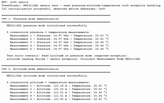
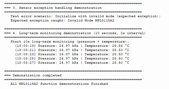
It can be seen that the corresponding monitoring data can be printed normally in the barometric pressure/altitude mode.
IV. Drivers
mpl3115a2_driver-1.0.1.zip 13 KB
5. BOM & Recommended Alternative Parts
None.
6. Revision History
Document Version | Date of Revision | Modifier | Modified Content |
v1.0 | 2026-03-30 | Ling Gaoxing | Initialize the document |
v1.0.1 | 2026-04-05 | Li Zisheng | The cover photo has not been taken, the production files have not been exported yet, and all other items have been sorted out. |
v1.0.2 | 2026-04-21 | Li Zisheng | The production documents have not been exported yet, and all the rest have been sorted out. |
v1.1 | 2026-04-23 | Xin Ruili | Create an open version of the document based on the internal document version v1.0.2. |
VII. Relevant Materials
7.1 Chip Datasheet
MPL3115A2-783414.pdf 1.1 MB
7.2 Unique Icons for PCB Silk Screen