Contents
- I. Module Introduction
- II. Introduction to Main Chips
- 2.1 Chip Overview
- 2.2 Pin Definition
- 2.3 Functional Block Diagram
- 2.4 Performance Parameters
- 2.5 Reference Circuit
- 2.6 Chip Configuration
- 2.7 Communication Interfaces and Related Protocols
- 2.8 PCB Routing Precautions
- III. Circuit Engineering
- 3.1 Circuit Source Engineering
- 3.2 Module Usage Instructions
- 3.3 Application Experiment
- IV. Drivers
- 5. BOM & Recommended Alternative Parts
- VI. Revision History
- 7. Relevant Materials
- 7.1 Chip Datasheet
- 7.2 Unique Icons for PCB Silk Screen
I. Module Introduction
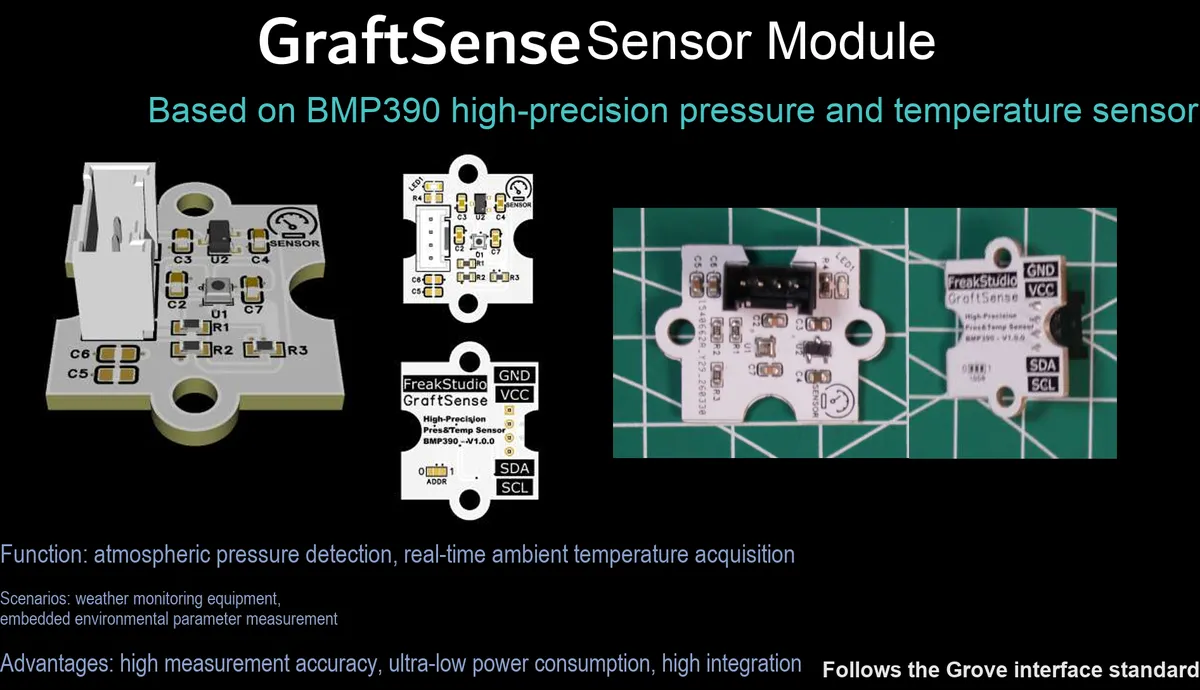
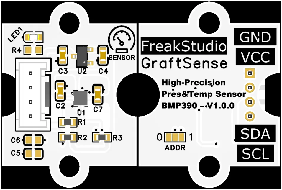
High-precision pressure and temperature sensor module based on BMP390, adopting the BMP390 chip solution, is a high-precision MEMS barometric pressure sensor with a built-in 24-bit ADC, which can directly read the barometric pressure and temperature data after factory calibration and compensation; the barometric pressure measurement range is 300~1250 hPa, with an absolute accuracy of ±0.5 hPa (equivalent to an altitude resolution of approximately ±8 cm), and the temperature measurement range is -40℃~+ 85℃ with an accuracy of ±0.5℃;Module integration LDO voltage regulation, power filtering and I²C pull-up circuit, equipped with a power indicator, supports I²C / SPI dual interfaces; in I²C mode, the address (0x76 / 0x77) can be selected via the ADDR pin, and it provides an INT interrupt pin, is compatible with 3.3V level MCUs, and is suitable for drone altitude control, indoor navigation, meteorological monitoring, and low-power IoT scenarios.
II. Introduction to Main Chips
BMP390 is a high-precision 24-bit MEMS barometric pressure and temperature sensor that supports dual interfaces of I²C and SPI. It features a barometric pressure range of 300~1250 hPa (accuracy: ±0.5 hPa, equivalent altitude resolution: ±8 cm) and a temperature range of -40~+ 85℃(accuracy: ±0.5℃). With built-in factory calibration and FIFO, it is suitable for altitude measurement and environmental monitoring scenarios.
2.1 Chip Overview
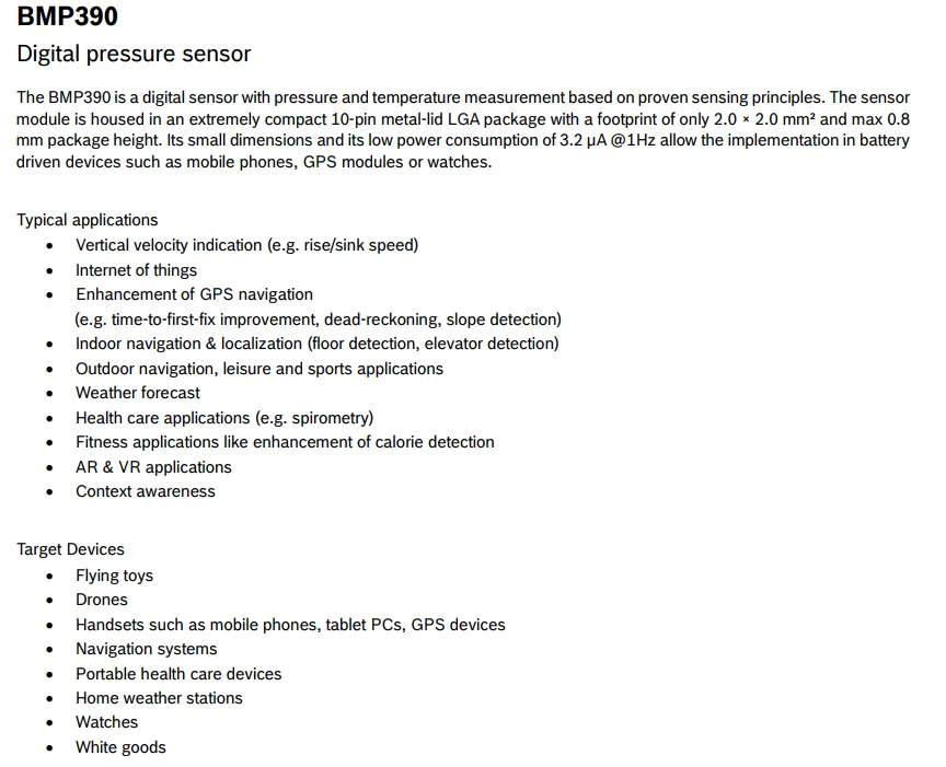
BMP390 is a digital sensor integrating pressure and temperature measurement, featuring a 10-pin metal lid LGA ultra-compact package (2.0×2.0 mm², height ≤0.8 mm) and outstanding low-power performance (only 3.2 μA at 1 Hz), making it ideal for battery-powered devices. Its typical applications cover vertical speed indication, Internet of Things, GPS navigation enhancement, indoor and outdoor navigation, weather forecasting, medical healthcare and AR / VR scenarios, with target devices including drones, smartphones, wearable watches, portable medical devices and home weather stations, etc.
2.2 Pin Definition
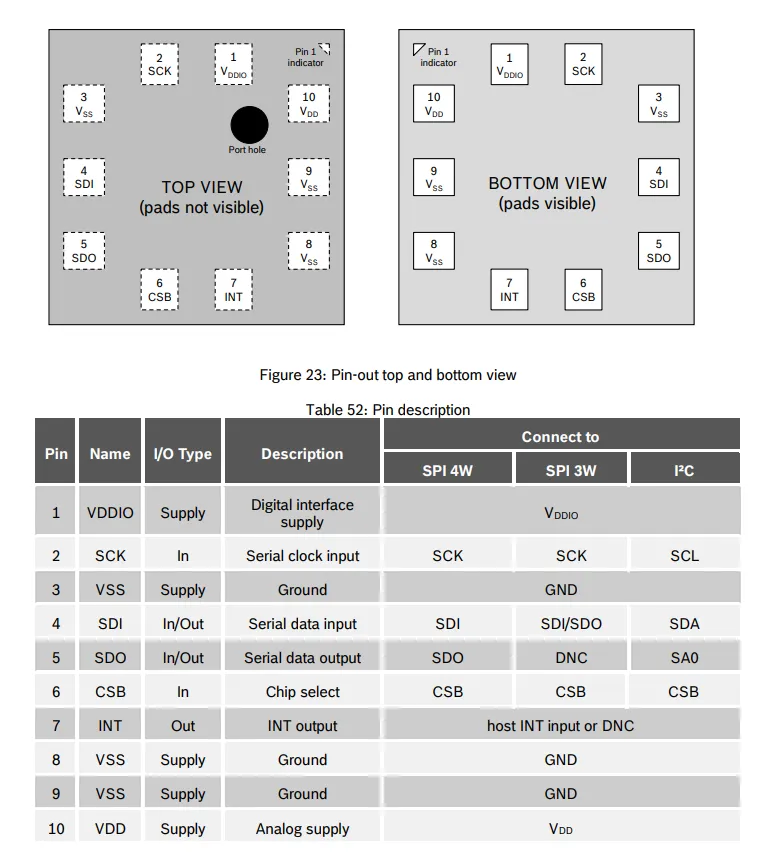
The BMP390 features clearly defined pin functions, including the analog power supply VDD, the digital interface power supply VDDIO, and multiple ground pins VSS; its communication interface supports I²C / SPI 3-wire / 4-wire modes, with corresponding pins being the serial clock SCK (which functions as SCL in I²C mode), serial data SDI / SDO (which function as SDA and SA0 in I²C mode respectively), as well as the chip select CSB and interrupt output INT pins, with clear pin connection configurations for different communication modes.
2.3 Functional Block Diagram
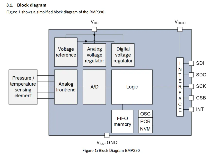
BMP390 collects raw analog signals via pressure/temperature sensitive elements, which are sent to the ADC for conversion into digital quantities after being processed by the analog front end; the logic unit then completes compensation and calculation in combination with the calibration parameters stored in the built-in NVM, and the results can be stored in the FIFO memory. Finally, it communicates with the main controller through the interface unit (supporting I²C / SPI) via the SDI / SDO / SCK / CSB pins, while the INT pin can output interrupt signals;The inside of the chip is powered by dual power supplies of VDD and VDDIO, and its stable operation is guaranteed by analog/digital voltage regulators, voltage references, and OSC / POR modules. All circuits take VSS as the ground reference.
2.4 Performance Parameters
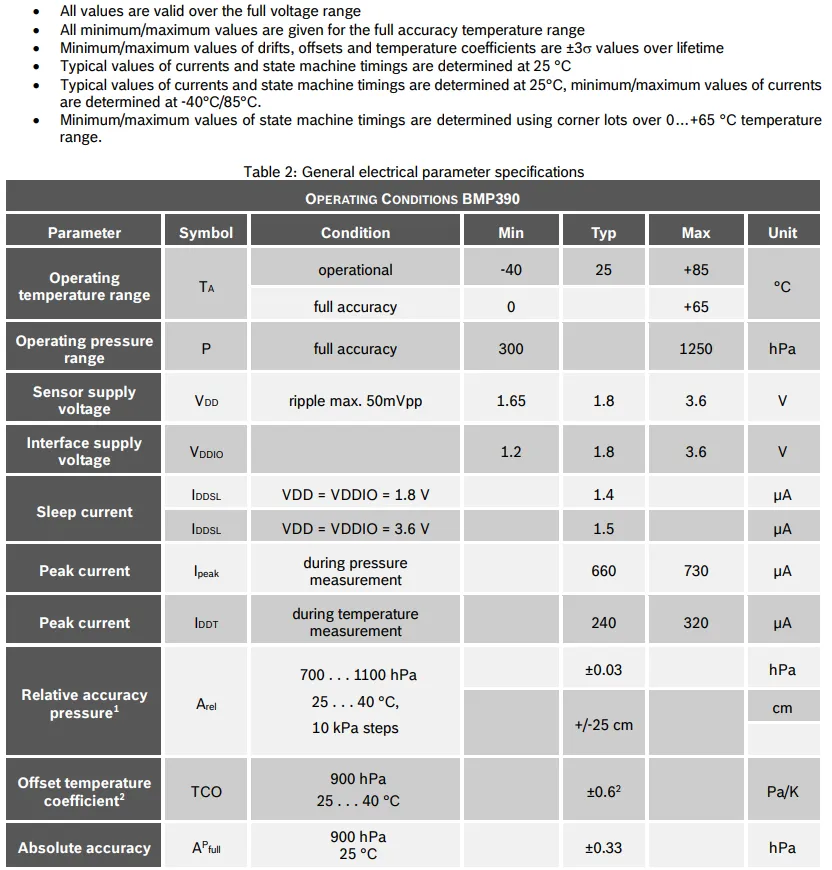
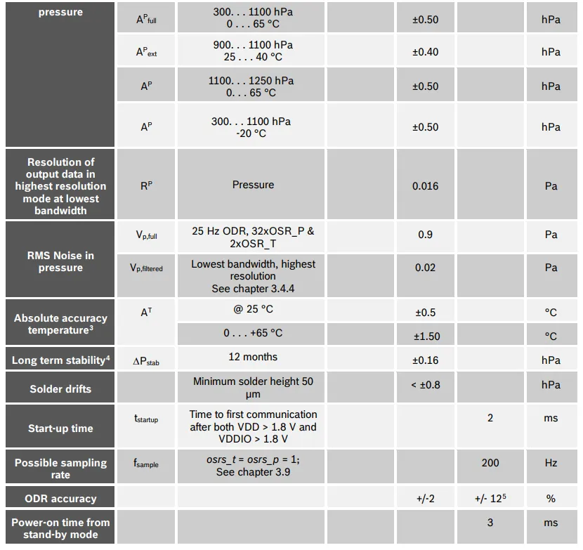
BMP390 operates within a temperature range of -40°C to + 85°C (full accuracy range: 0°C to + 65°C), with a barometric pressure measurement range of 300 to 1250 hPa; the sensor supply voltage VDD ranges from 1.65 to 3.6 V, the interface supply voltage VDDIO ranges from 1.2 to 3.6 V, the sleep current is as low as 1.4-1.5 μA, the peak current for pressure measurement is 660-730 μA, and the peak current for temperature measurement is 240-320 μA;In terms of accuracy, the relative accuracy reaches up to ±0.03 hPa (equivalent to ±25 cm height), the absolute accuracy is ±0.33-0.50 hPa, and the temperature accuracy is ±0.5℃(from 0 to + 65℃), RMS noise is as low as 0.02-0.9 Pa, the long-term stability is ±0.16 hPa within 12 months, the start-up time is 2 ms, the maximum sampling rate is 200 Hz, and the standby power-on time is 3 ms. All parameters cover the full voltage and temperature ranges with extreme values marked.
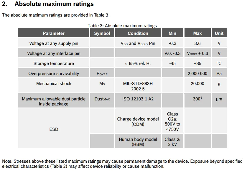
BMP390 has a supply pin voltage range of -0.3 to 3.6 V, and an interface pin voltage range of Vss -0.3 to VDDIO + 0.3 V; its storage temperature ranges from -45 to + 85 °C, it can withstand an overpressure of 2 MPa and a mechanical shock of 20000 g, and the maximum allowable dust particle size inside the package is 300 μm;ESD protection meets the ratings of HBM 2 kV and CDM 500 to 750 V, and exceeding these ratings will cause permanent damage to the device.
2.5 Reference Circuit
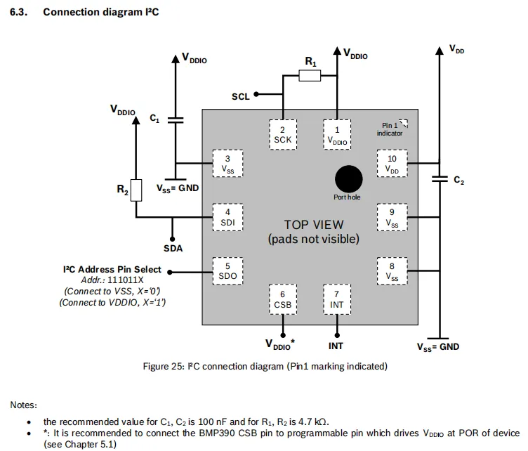
The BMP390 chip operates on VDD and VDDIO dual power supplies, with a 100 nF filter capacitor C₂ and C₁ connected to ground respectively;I²C communication pins SCL and SDA are each connected to VDDIO via a 4.7 kΩ pull-up resistor (R₁ and R₂ respectively); the SDO pin is used for address selection (the address is 0x76 when connected to VSS, and 0x77 when connected to VDDIO pin is recommended to be connected to a programmable pin, the CSB pin is recommended to be connected to a programmable pin, the INT pin can serve as an interrupt output, and all VSS pins are grounded. The overall circuit is simple, and can directly implement I²C communication and high-precision pressure/temperature acquisition.
2.6 Chip Configuration
None.
2.7 Communication Interfaces and Related Protocols
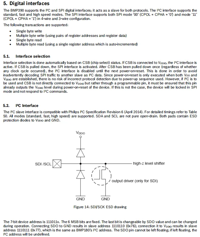
BMP390 features a digital interface that supports both I²C and SPI dual interfaces, and automatically switches based on the status of the CSB pin (when connected to VDDIO, it works in I²C mode; when pulled low, it switches to SPI mode);I²C is compatible with standard / fast / high-speed modes, its 7-bit address is 111011X, which is determined by the SDO pin (connected to GND corresponds to 0x76, connected to VDDIO corresponds to 0x77);SPI supports 4-wire / 3-wire configuration, and is compatible with modes ' 00 ' and ' 11 ';It supports single/multi-byte read and write, and multi-byte read features auto-incrementing addresses; the interface pins have built-in ESD protection diodes to ensure communication stability.
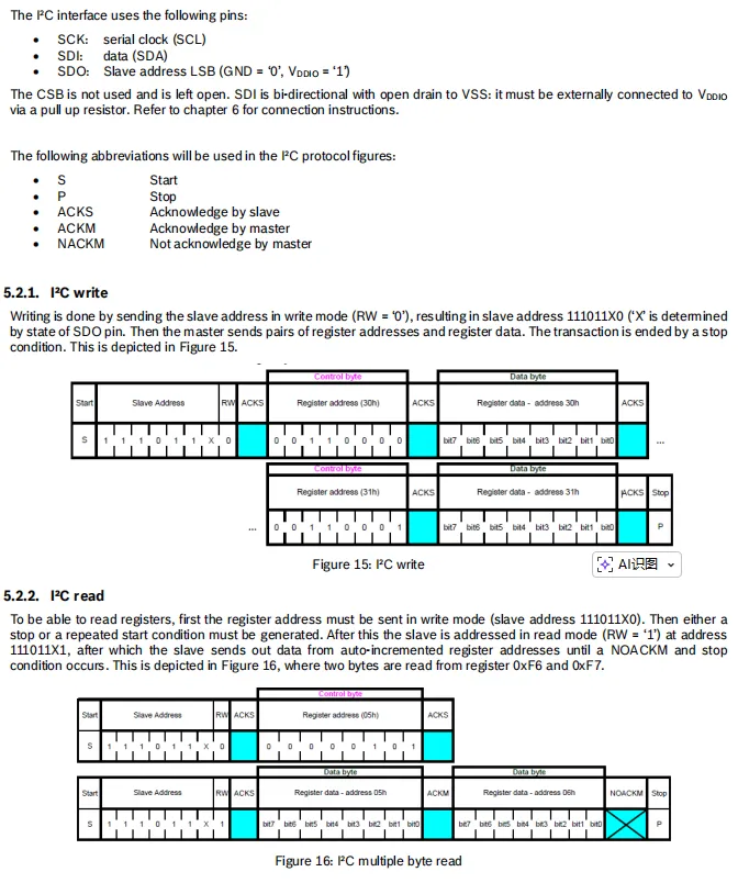
BMP390 I²C interface uses the following pins: SCK (SCL), SDI (SDA), SDO (address LSB), with the CSB pin left floating. For write operations, first send the slave address (RW = 0) with the write bit set: 111011X0, then transmit the register address and data in sequence; it supports transmission of multiple address-data pairs.For a read operation, the register address shall first be sent in write mode, then a repeated START or STOP condition is generated before the slave address with a read bit (RW = 1)(111011X1) is sent. The slave automatically outputs register data with auto-incrementing addresses until the master sends a non-acknowledge (NACKM) to terminate the transmission. The Sequence Diagram clearly illustrates the complete process of single/multi-byte read and write operations.
2.8 PCB Routing Precautions
None.
III. Circuit Engineering
3.1 Circuit Source Engineering
To obtain the circuit source project, please follow the official account [Freak Embedded].
3.2 Module Usage Instructions
The schematic diagram of this module is shown below:
SCH_High-Precision Pressure and Temperature Sensor Based on BMP390-V1.0.0_2026-03-30.pdf 2.2 MB
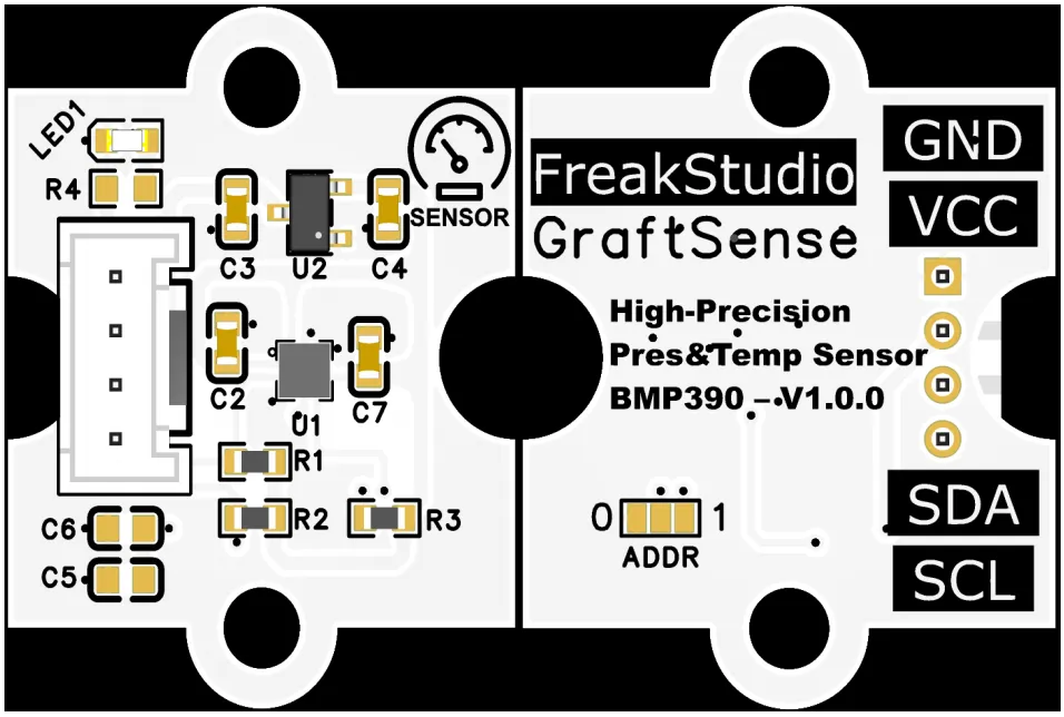
This module provides an I²C communication interface: it supports standard / fast / high-speed I²C communication rates, and allows flexible selection of the ADDR pin to configure the I²C slave address (ADDR = 0 corresponds to 0x76, while ADDR = 1 corresponds to 0x77), and is compatible with 3.3V level MCU s;The module integrates LDO voltage regulation, power filtering and I²C pull-up circuits, and is equipped with a power indicator. It can directly read high-precision barometric pressure (300~1250 hPa, absolute accuracy ±0.5 hPa, equivalent height resolution of approximately ±8 cm) and temperature (-40℃~+ 85℃, accuracy ±0.5℃) data after factory calibration and compensation. Meanwhile, it supports SPI interface and INT interrupt output, and is suitable for drone altitude control, indoor navigation, meteorological monitoring and low-power IoT scenarios, providing reliable environmental parameter collection and interaction capabilities for the system.
3.3 Application Experiment
Here, we use the GraftPort-RP2040 development board for testing, and the high-precision pressure and temperature sensor based on BMP390 uses the I2C interface to communicate with the master.
Here, we first use the HY2.0-4P connection cable to connect the module to the GraftPort-RP2040 development board's I2C0 interface:
The module connections are shown in the following table:
Development Board Pins | Module Pins | Description |
Pin 4 |
|
|
Pin 5 |
|
|
Here, we need to search for the relevant driver packages on uPyPI: https://upypi.net/zh/
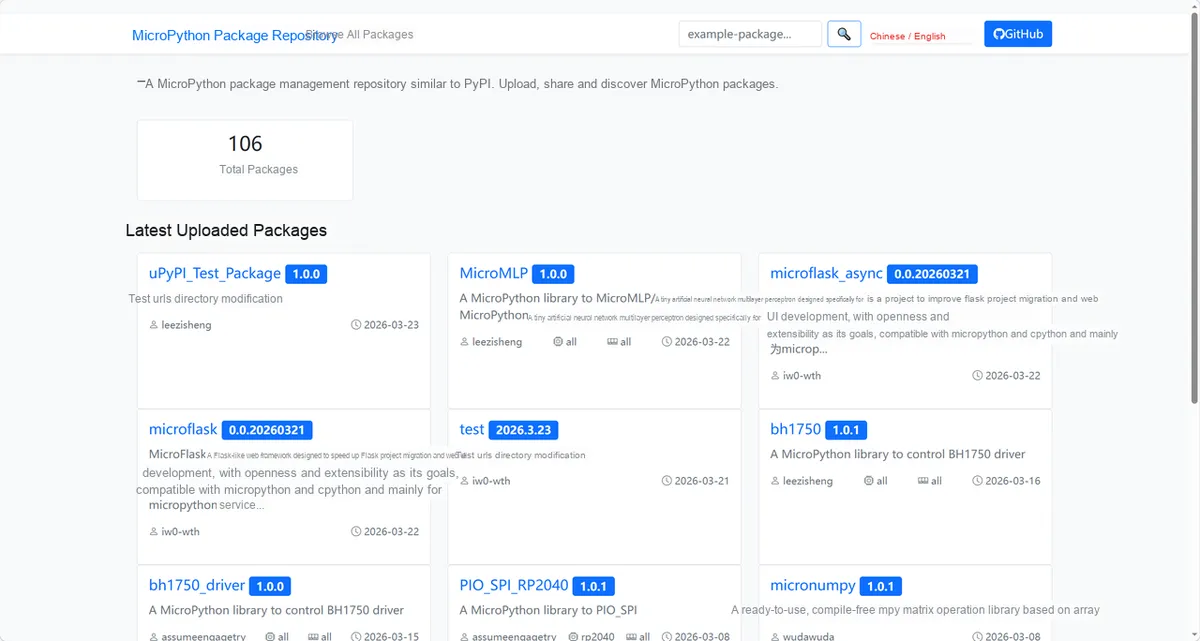
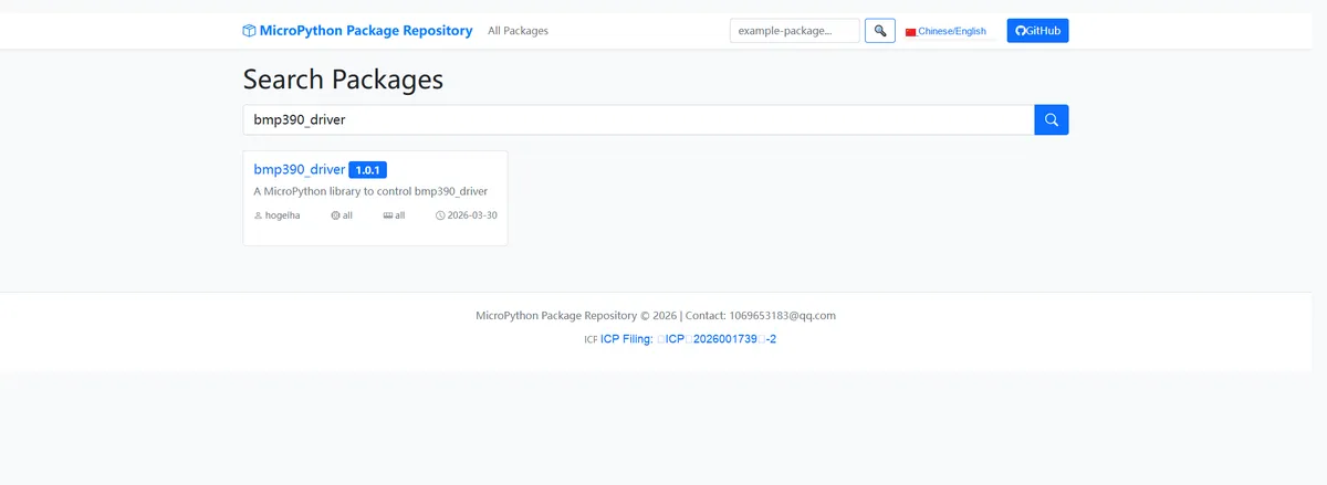
Enter bmp390_driver to search, and the following will be displayed:
Click to copy the local installation command:
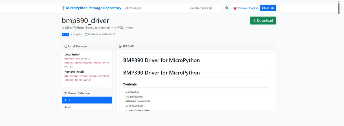
Import the module driver library code via the mip tool. Below are the usage commands for the mpremote tool:
mpremote mip install https://upypi.net/pkgs/bmp390_driver/1.0.0Import the high-precision pressure and temperature sensor based on BMP390 - MicroPython driver code, then copy the following main.py code into our project:
# Python env   : MicroPython v1.23.0
# -*- coding: utf-8 -*-
# @Time    : 2025/9/8 4:52 PM
# @Author  : octaprog7
# @File    : main.py
# @Description : BMP390 pressure sensor test program

# ======================================== Import Modules =========================================
from machine import I2C, Pin
import bmp390
import time
from bmp390 import I2cAdapter

# ======================================== Global Variables ============================================
# Define I2C configuration constants
I2C_SCL_PIN = 5  # SCL pin (for Raspberry Pi Pico)
I2C_SDA_PIN = 4  # SDA pin (for Raspberry Pi Pico)
I2C_FREQ = 400_000  # I2C communication frequency
TARGET_SENSOR_ADDR = 0x77  # BMP390 default I2C address (0x76 is optional, adjust according to hardware wiring)


# ======================================== Functions ============================================
def pa_mmhg(value: float) -> float:
    """
    Convert atmospheric pressure from pascals to millimeters of mercury.
    Args:
        value: pressure value in pascals

    Returns:
        Converted pressure value in millimeters of mercury

    Notes:
        The conversion factor is 7.50062e-3

    ==========================================
    Convert air pressure from Pascal to mm Hg.
    Args:
        value: pressure in Pascal

    Returns:
        pressure in mm Hg

    Notes:
        conversion factor is 7.50062e-3
    """
    return 7.50062e-3 * value


# ======================================== Custom Classes ============================================

# ======================================== Initialization configuration ===========================================
time.sleep(3)
print("FreakStudio: BMP390 sensor test starting...")

# Initialize the I2C bus in the example style + scan I2C devices
# 1. Initialize the I2C bus
i2c_bus = I2C(0, scl=Pin(I2C_SCL_PIN), sda=Pin(I2C_SDA_PIN), freq=I2C_FREQ)
# 2. Start scanning for devices on the I2C bus
devices_list: list[int] = i2c_bus.scan()
print("START I2C SCANNER")

# 3. Check the I2C device scan results
if len(devices_list) == 0:
    print("No i2c device !")
    raise SystemExit("I2C scan found no devices, program exited")
else:
    print("i2c devices found:", len(devices_list))

# 4. Iterate over the address list to initialize the target sensor (matching the example logic)
ps = None  # Sensor object initialization
for device in devices_list:
    if device == TARGET_SENSOR_ADDR:
        print("I2c hexadecimal address:", hex(device))
        try:
            # Initialize the I2C adapter and the BMP390 sensor
            adaptor = I2cAdapter(i2c_bus)
            ps = bmp390.Bmp390(adaptor)
            print("Target sensor (BMP390) initialization successful")
            break
        except Exception as e:
            print(f"Sensor Initialization failed: {e}")
            continue
else:
    # Raise an exception if the target address is not found after iterating
    raise Exception(f"No BMP390 found (target address: {hex(TARGET_SENSOR_ADDR)}, found addresses: {[hex(d) for d in devices_list]})")

# Read the sensor ID
res = ps.get_id()
print(f"chip_id: {res}")
# Software reset the sensor to ensure it enters a known state
ps.soft_reset()
print(f"pwr mode: {ps.get_power_mode()}")

# Read the calibration coefficients

calibration_data = [ps.get_calibration_coefficient(index) for index in range(14)]
print(f"Calibration data: {calibration_data}")

# Get the event, interrupt status and FIFO length
print(f"Event: {ps.get_event()}; Int status: {ps.get_int_status()}; FIFO length: {ps.get_fifo_length()}")

# Set an alias for the delay function
delay_func = time.sleep_ms

# Configure the sensor parameters
ps.set_oversampling(pressure_oversampling=2, temperature_oversampling=3)
ps.set_sampling_period(5)
ps.set_iir_filter(2)

# ========================================  Main Program  ============================================
print("Single-shot measurement mode on demand!")
print(f"pwr mode: {ps.get_power_mode()}")
print(f"conversion time in [us]: {ps.get_conversion_cycle_time()}")
for _ in range(20):
    # Start single measurement mode
    ps.start_measurement(enable_press=True, enable_temp=True, mode=1)
    delay_func(300)
    # Read the data-ready status
    temperature_ready, pressure_ready, cmd_ready = ps.get_data_status()
    if cmd_ready and pressure_ready:
        t, p = ps.get_temperature(), ps.get_pressure()
        pm = ps.get_power_mode()
        print(f"Temperature: {t} \xB0C; pressure: {p} Pa ({pa_mmhg(p)} mm Hg); pwr_mode: {pm} ")
    else:
        print(f"Data ready: temp {temperature_ready}, press {pressure_ready}")

print("Continuous periodic measurement mode!")
# Start continuous measurement mode
ps.start_measurement(enable_press=True, enable_temp=True, mode=2)
print(f"pwr mode: {ps.get_power_mode()}")
for values in ps:
    delay_func(300)
    d_status = ps.get_data_status()
    if d_status.cmd_decoder_ready and d_status.press_ready:
        t, p, tme = values.T, values.P, ps.get_sensor_time()
        pm = ps.get_power_mode()
        print(f"Temperature: {t} \xB0C; pressure: {p} Pa ({pa_mmhg(p)} mm Hg); pwr_mode: {pm}")
    else:
        print(f"Data ready: temp {d_status.temp_ready}, press {d_status.press_ready}")
Burn the code, open the terminal, and the output is as follows:
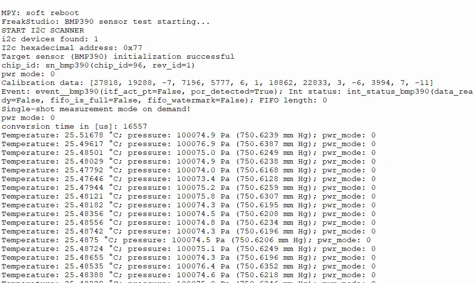
It cyclically collects and outputs real-time data of the temperature and barometric pressure of the current environment.
IV. Drivers
bmp390_driver-1.0.1.zip 18 KB
5. BOM & Recommended Alternative Parts
None.
VI. Revision History
Document Version | Date Modified | Modifier | Modify Content |
v1.0 | 2026-03-30 | Ling Gaoxing | Initialize the document |
v1.0.1 | 2026-04-21 | Li Zisheng | The production documents have not been exported yet, and all the rest have been sorted out. |
v1.1 | 2026-04-23 | Xin Ruili | Create an open version of the document, based on the internal document version v1.0.1. |
7. Relevant Materials
7.1 Chip Datasheet
BMP390.pdf 1.8 MB
7.2 Unique Icons for PCB Silk Screen