Contents
- I. Module Introduction
- II. Introduction to Main Chips
- 2.1 Chip Overview
- 2.2 Pin Definition
- 2.3 Functional Block Diagram
- 2.4 Performance Parameters
- 2.5 Reference Circuit
- 2.6 Chip Configuration
- 2.7 Communication Interfaces and Related Protocols
- 2.8 PCB Routing Precautions
- III. Circuit Engineering
- 3.1 Circuit Source Engineering
- 3.2 Module Usage Instructions
- 3.3 Application Experiment
- IV. Drivers
- 5. BOM & Recommended Alternative Parts
- VI. Revision History
- 7. Relevant Materials
- 7.1 Chip Datasheet
- 7.2 Unique Icons for PCB Silk Screen
I. Module Introduction
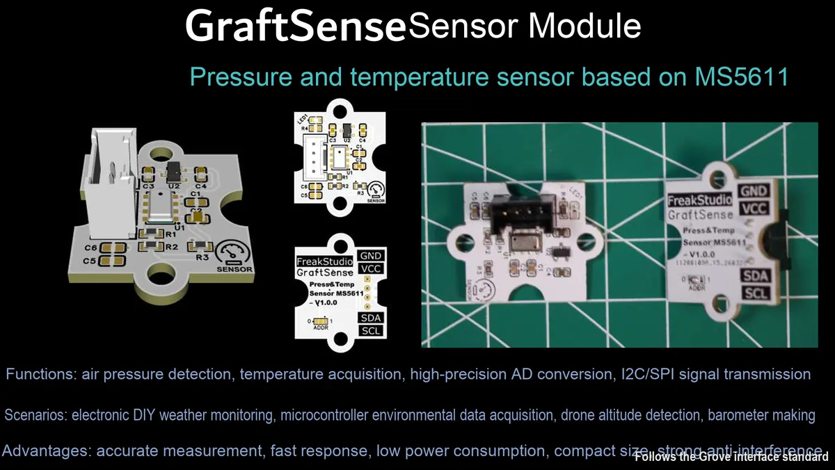
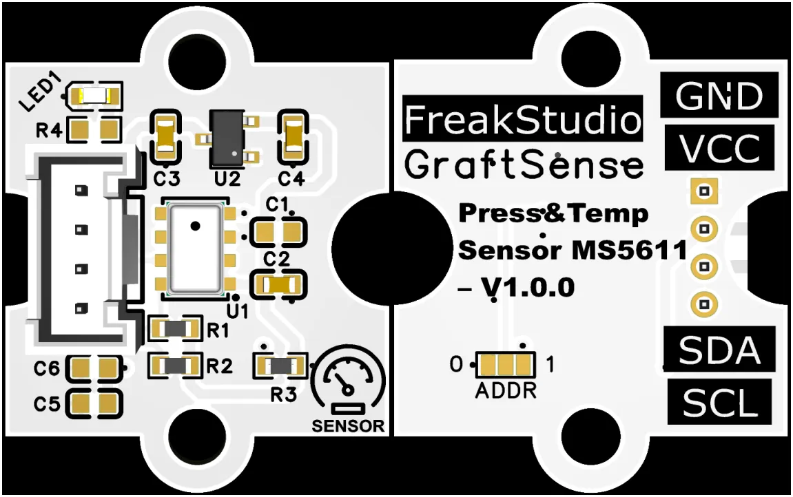
MS5611-based pressure and temperature sensor module, which adopts the MS5611 chip solution, is a high-resolution MEMS barometric pressure sensor with a built-in 24-bit ADC and factory calibration coefficients, capable of outputting compensated barometric pressure and temperature data; it features a barometric pressure measurement range of 10~1200 mbar with a maximum resolution of 0.012 mbar (equivalent to an altitude resolution of approximately 10 cm), and a temperature measurement range of -40℃~+ 85℃ with an accuracy of ±0.8℃;The module integrates voltage regulators, power filtering and voltage regulators, power filtering and I²C pull-up circuits, is equipped with a power indicator, supports I²C / SPI dual interfaces. In I²C mode, the address (0x76 / 0x77) can be selected via the ADDR pin. It is compatible with 3.3V level MCU, and is suitable for altitude measurement, weather monitoring, drone navigation and low-power IoT scenarios.
II. Introduction to Main Chips
MS5611 is a high-resolution 24-bit MEMS barometric pressure and temperature sensor that supports dual interfaces of I²C and SPI. It features a pressure measurement range of 10~1200 mbar (with a resolution of 0.012 mbar, equivalent to an approximate altitude resolution of 10 cm), a temperature measurement range of -40~+ 85℃(with an accuracy of ±0.8℃), and built-in factory calibration coefficients, making it suitable for altitude measurement and environmental monitoring scenarios.
2.1 Chip Overview
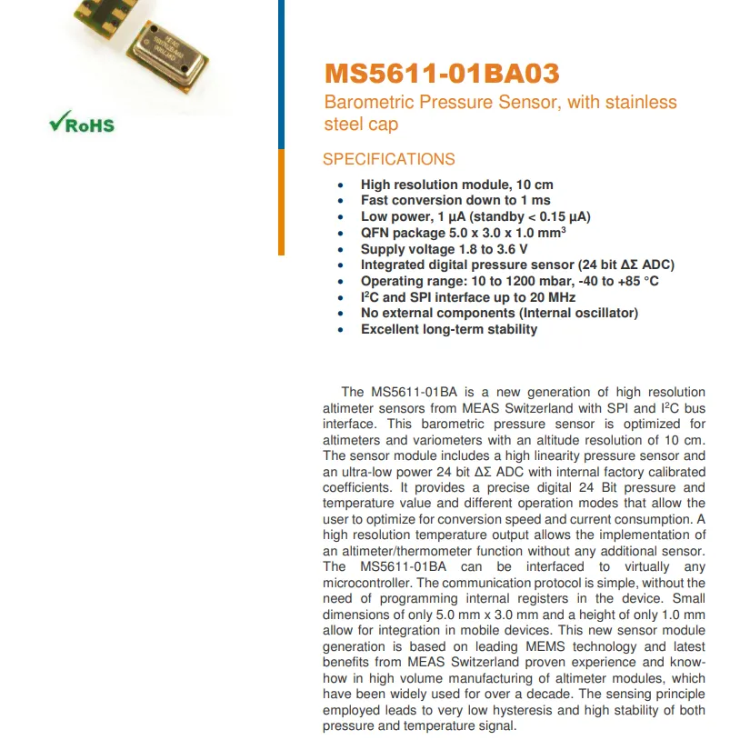
MS5611-01BA03 is a high-resolution barometric pressure sensor encapsulated in a stainless steel cap, with a built-in 24-bit ΔΣ ADC and factory-calibrated coefficients, capable of outputting high-precision barometric pressure and temperature data;Air pressure range: 10~1200 mbar, altitude resolution up to 10 cm, maximum conversion speed 1 ms, standby current as low as < 0.15 μA, operating voltage 1.8~3.6 V, adopts 5.0×3.0×1.0 mm³ QFN package, supports I²C / SPI interface (max. 20 MHz), requires no external components, features excellent long-term stability, and is suitable for scenarios such as altimeters, variometers and mobile devices.
2.2 Pin Definition
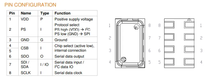
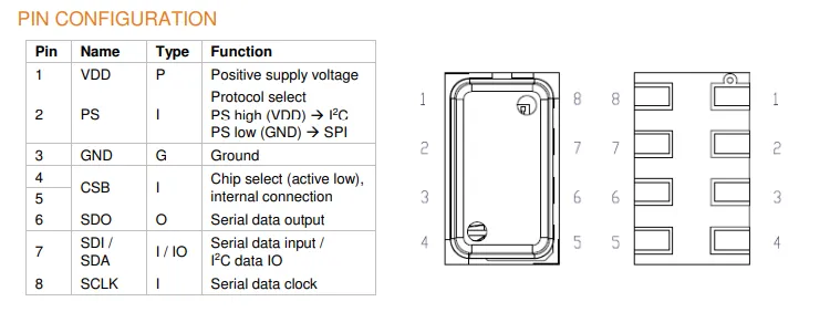
The MS5611 chip adopts an 8-pin package, with pin 1 serving as the power supply VDD and pin 3 as the ground GND; pin 2 (PS) is used for Communication Protocol selection (connected to VDD for I²C, connected to GND for SPI), pins 4/5 are the chip select CSB (active low), pin 6 is the serial data output SDO, pin 7 is the serial data input / I²C data IO (SDI / SDA), and pin 8 is the serial clock SCLK.
2.3 Functional Block Diagram
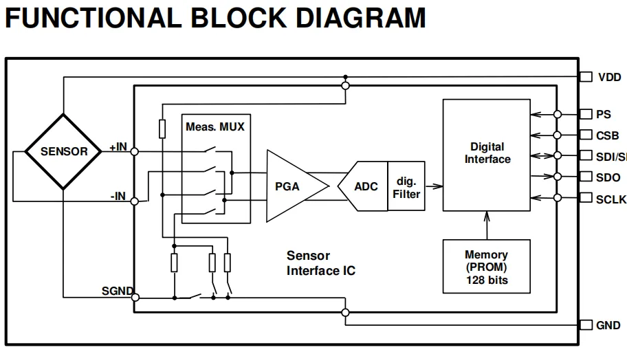
MS5611 collects differential analog signals via its pressure/temperature sensing element (SENSOR); after being gated by the measurement multiplexer (Meas. MUX), the signals are sent to a programmable gain amplifier (PGA) for amplification, then converted into digital values by an ADC. After digital filtering, compensation calculation is performed using the factory calibration coefficients stored in the 128-bit PROM. Finally, through the digital interface unit (Digital Interface), the PS pin selects the I²C / SPI communication mode, and the chip interacts with the main controller via pins including SDI / SDA, SDO, and SCLK. Meanwhile, the chip is powered by VDD and GND, with its internal circuitry ensuring stable signal processing and reliable data output.
2.4 Performance Parameters
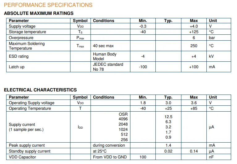
MS5611 In terms of its limiting parameters, the power supply voltage ranges from -0.3 V to + 4.0 V, the storage temperature ranges from -40°C to + 125°C, it can withstand an overpressure of 6 bar and a soldering temperature of 250°C (for 40 seconds), ESD protection reaches HBM ±4 kV, with a latch-up current of ±100 mA;In terms of electrical characteristics, it features an operating voltage of 1.8~3.6 V (typical: 3.0 V) and an operating temperature range of -40~+ 85℃; at a 1 Hz sampling rate, the supply current decreases as the OSR decreases (only 0.9 μA at 256× OSR), with a peak conversion current of 1.4 mA and a standby current as low as 0.02 μA. It is recommended to connect a 100 nF capacitor between VDD and GND, which overall reflects its low power consumption and wide environmental adaptability.
2.5 Reference Circuit
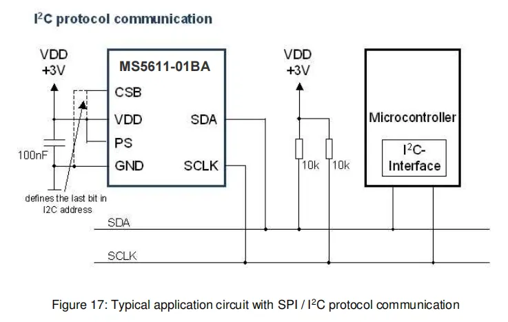
The MS5611 chip is powered by a 3V VDD supply, with a 100nF filter capacitor connected to ground; the PS pin is connected to VDD to select the I²C communication mode, and the CSB pin level determines the last bit of the I²C address;The SDA and SCLK pins are each connected to VDD via a 10kΩ pull-up resistor, then connected to the microcontroller's I²C interface to enable communication between the main controller and the sensor. The overall circuit is simple, and can stably complete the acquisition and transmission of high-precision barometric pressure and temperature data.
2.6 Chip Configuration
None.
2.7 Communication Interfaces and Related Protocols
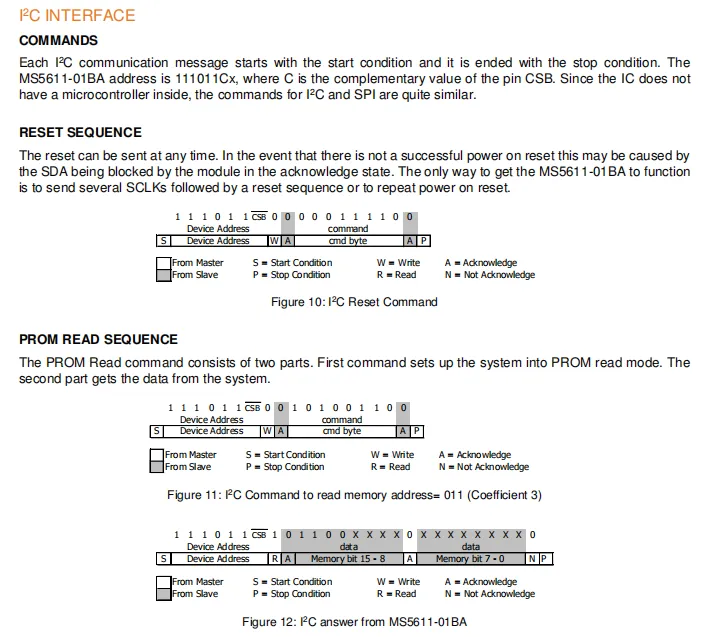
MS5611 I²C communication starts with a start condition and ends with a stop condition, with the device address being 111011Cx, where C is determined by the inverted level of the CSB pin; the reset sequence can be sent at any time to release the SDA blocking state, which requires sending multiple SCLK pulses first before executing the reset command or powering the device on again.PROM read operation is divided into two steps: first send a command to enter the read mode, then read the calibration coefficient data. The Sequence Diagram clearly shows the complete PROM read command and slave response process of the I²C transmission, including the response and data transmission logic of the master/slave devices.
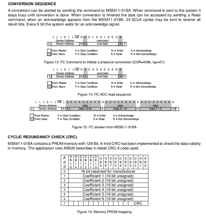
MS5611 I²C conversion requires sending a start command first; after the chip remains busy until the conversion is completed, a read command is sent to obtain the 24-bit result data. The Sequence Diagram clearly illustrates the complete ADC reading and command sending I²C transmission process; the chip has a built-in 128-bit PROM that stores 6 sets of 16-bit calibration coefficients and 4-bit CRC check bits for data validity verification, and the overall process ensures the reliable execution of pressure/temperature measurement and data calibration.
2.8 PCB Routing Precautions
None.
III. Circuit Engineering
3.1 Circuit Source Engineering
To obtain the circuit source project, please follow the official account [Freak Embedded].
3.2 Module Usage Instructions
The schematic diagram of this module is shown below:
SCH_Pressure and Temperature Sensor Based on MS5611-V1.0.0_2026-03-30.pdf 2.0 MB
This module provides an I²C communication interface: it supports standard I²C communication rates, and the ADDR pin (i. e., the chip's CSB pin) allows flexible configuration of the I²C slave address (ADDR = 0 corresponds to 0x77, while ADDR = 1 corresponds to 0x76), and is compatible with 3.3V level MCUs;The module integrates LDO voltage regulation, power filtering and I²C pull-up circuits, and is equipped with a power indicator. It can output high-precision barometric pressure (10~1200 mbar, resolution 0.012 mbar, equivalent altitude resolution of approximately 10 cm) and temperature (-40℃~+ 85℃, accuracy ±0.8℃) data that have undergone factory calibration and compensation. Meanwhile, it supports the SPI interface, and is suitable for altitude measurement, meteorological monitoring, drone navigation and low-power IoT scenarios, providing reliable environmental parameter collection and interaction capabilities for the system.
3.3 Application Experiment
Here, we use the GraftPort-RP2040 development board for testing, and the MS5611-based pressure and temperature sensor communicates with the main controller via the I2C interface.
Here, we first use the HY2.0-4P connection cable to connect the module to the GraftPort-RP2040 development board's I2C0 interface:
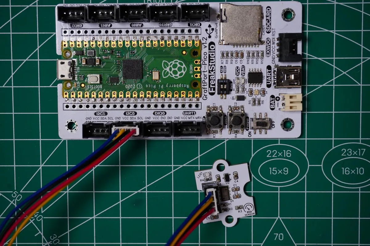
The module connections are shown in the following table:
Development Board Pins | Module Pins | Description |
Pin 4 |
|
|
Pin 5 |
|
|
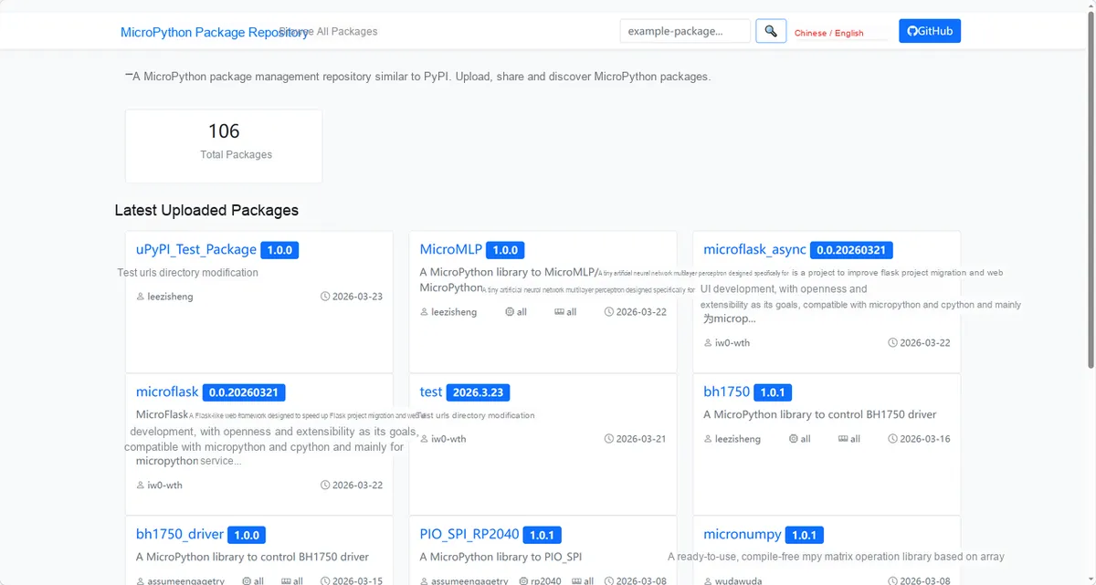
Here, we need to search for the relevant driver packages on uPyPI: https://upypi.net/zh/
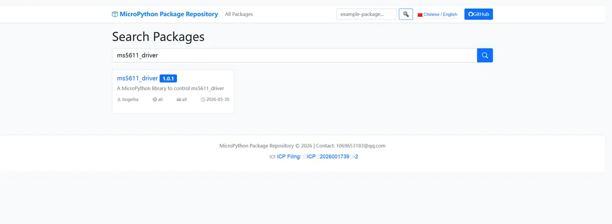
Enter ms5611_driver to search, and the following will be displayed:
Click to copy the local installation command:
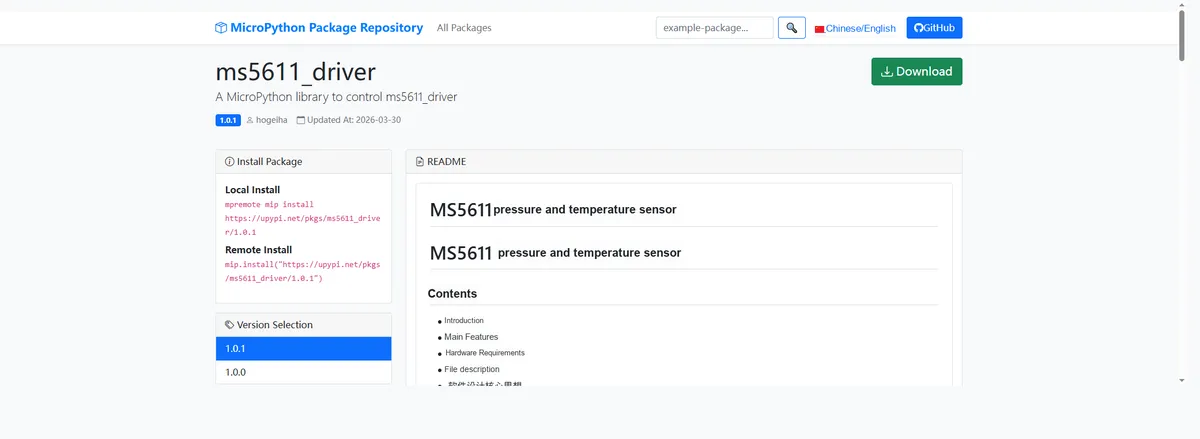
Import the module driver library code via the mip tool. Below are the usage commands for the mpremote tool:
mpremote mip install https://upypi.net/pkgs/ms5611_driver/1.0.0After importing the MicroPython driver code for the MS5611-based pressure and temperature sensor, copy the following main.py code into our project:
# Python env   : MicroPython v1.23.0
# -*- coding: utf-8 -*-
# @Time    : 2026/3/12 5:20 PM
# @Author  : jposada202020
# @File    : main.py
# @Description : MS5611 pressure sensor test: configure oversampling rate, read temperature and pressure data, calculate average and fluctuation

# ======================================== Import Modules =========================================

import time
from machine import Pin, I2C
from ms5611 import MS5611

# ======================================== Global Variables ============================================

# I2C pin configuration (RP2040)
I2C_SDA_PIN = 4
I2C_SCL_PIN = 5
I2C_FREQ = 400000
# MS5611 sensor I2C address (0x77 when CSB is connected to VCC, 0x76 when connected to GND)
MS5611_I2C_ADDR = 0x77
# Measurement delay configuration
SHORT_DELAY = 0.3
MEDIUM_DELAY = 0.5
LONG_DELAY = 0.8
OVERSAMPLING_DELAY = 1.0

# ======================================== Functions ============================================


def init_i2c(sda_pin, scl_pin, freq):
    """Initialize I2C bus for RP2040"""
    try:
        i2c = I2C(0, sda=Pin(sda_pin), scl=Pin(scl_pin), freq=freq)
        scanned_devices = [hex(addr) for addr in i2c.scan()]
        print(f"I2C initialized successfully, scanned devices: {scanned_devices}")
        return i2c
    except Exception as e:
        print(f"I2C initialization failed: {e}")
        return None


def create_ms5611_sensor(i2c, address):
    """Create MS5611 sensor object with exception handling"""
    try:
        ms_sensor = MS5611(i2c, address=address)
        print("MS5611 sensor initialized successfully")
        return ms_sensor
    except RuntimeError as e:
        print(f"MS5611 sensor not found: {e}")
        return None
    except OSError as e:
        print(f"I2C communication error: {e}")
        return None


def print_separator(title):
    """Print separator line to improve output readability"""
    print("\n" + "=" * 65)
    print(f"=== {title}")
    print("=" * 65)


def safe_read_measurements(sensor):
    """Safely read temperature and pressure data with exception handling"""
    try:
        temperature, pressure = sensor.measurements
        return (temperature, pressure), True
    except OSError as e:
        if "EIO" in str(e):
            print(f"I2C communication error (Errno 5): {e}, retrying...")
        else:
            print(f"Failed to read measurements: {e}")
        return (0.0, 0.0), False
    except Exception as e:
        print(f"Unknown error: {e}")
        return (0.0, 0.0), False


def safe_set_oversample_rate(sensor, param_name, value, valid_values):
    """Safely set oversampling rate with parameter validation and exception handling"""
    try:
        if value not in valid_values:
            print(f"Invalid value {value}, skipping")
            return False

        setattr(sensor, param_name, value)
        current_value = getattr(sensor, param_name)
        print(f"Set successfully - Current {param_name}: {current_value} (Value: {value})")
        return True
    except ValueError as e:
        print(f"Invalid parameter value: {e}")
        return False
    except OSError as e:
        print(f"I2C error when setting {param_name}: {e}")
        return False
    except Exception as e:
        print(f"Failed to set {param_name}: {e}")
        return False


def calculate_statistics(data_list):
    """Calculate average, max, min and fluctuation of measurement data"""
    if not data_list:
        return 0.0, 0.0, 0.0

    avg_value = sum(data_list) / len(data_list)
    max_value = max(data_list)
    min_value = min(data_list)
    fluctuation = max_value - min_value

    return avg_value, fluctuation, max_value, min_value


# ======================================== Custom Classes ============================================

# ======================================== Initialization configuration ===========================================

time.sleep(3)
print("FreakStudio: MS5611 pressure sensor test with oversampling rate configuration")

# Initialize I2C bus
i2c_bus = init_i2c(I2C_SDA_PIN, I2C_SCL_PIN, I2C_FREQ)
if not i2c_bus:
    raise SystemExit("I2C initialization failed, program exited")

# Create MS5611 sensor instance
ms5611_sensor = create_ms5611_sensor(i2c_bus, MS5611_I2C_ADDR)
if not ms5611_sensor:
    raise SystemExit("MS5611 initialization failed, program exited")

# ========================================  Main Program  ============================================

# 1. Temperature oversampling rate configuration demo (fixed pressure OSR=4096)
print_separator("1. Temperature Oversampling Rate Configuration (Pressure OSR=4096)")
safe_set_oversample_rate(ms5611_sensor, "pressure_oversample_rate", MS5611.PRESS_OSR_4096, MS5611.pressure_oversample_rate_values)

for temp_osr in MS5611.temperature_oversample_rate_values:
    if safe_set_oversample_rate(ms5611_sensor, "temperature_oversample_rate", temp_osr, MS5611.temperature_oversample_rate_values):
        print("    3 consecutive measurements:")
        for i in range(3):
            (temp, press), success = safe_read_measurements(ms5611_sensor)
            if success:
                print(f"      Measurement {i+1} - Temperature: {temp:.2f}°C, Pressure: {press:.2f}KPa")
            time.sleep(MEDIUM_DELAY)
    time.sleep(OVERSAMPLING_DELAY)

# 2. Pressure oversampling rate configuration demo (fixed temperature OSR=4096)
print_separator("2. Pressure Oversampling Rate Configuration (Temperature OSR=4096)")
safe_set_oversample_rate(ms5611_sensor, "temperature_oversample_rate", MS5611.TEMP_OSR_4096, MS5611.temperature_oversample_rate_values)

for press_osr in MS5611.pressure_oversample_rate_values:
    if safe_set_oversample_rate(ms5611_sensor, "pressure_oversample_rate", press_osr, MS5611.pressure_oversample_rate_values):
        print("    3 consecutive measurements:")
        for i in range(3):
            (temp, press), success = safe_read_measurements(ms5611_sensor)
            if success:
                print(f"      Measurement {i+1} - Temperature: {temp:.2f}°C, Pressure: {press:.2f}KPa")
            time.sleep(MEDIUM_DELAY)
    time.sleep(OVERSAMPLING_DELAY)

# 3. Combined oversampling rate demo (low/medium/high combinations)
print_separator("3. Combined Oversampling Rate Demo (Low/Medium/High)")
osr_combinations = [
    (MS5611.TEMP_OSR_256, MS5611.PRESS_OSR_256),  # Low precision, fast speed
    (MS5611.TEMP_OSR_1024, MS5611.PRESS_OSR_1024),  # Medium precision
    (MS5611.TEMP_OSR_4096, MS5611.PRESS_OSR_4096),  # High precision, slow speed
]

for idx, (temp_osr, press_osr) in enumerate(osr_combinations):
    print(f"\n  Combination {idx+1}:")
    # Set temperature oversampling rate
    safe_set_oversample_rate(ms5611_sensor, "temperature_oversample_rate", temp_osr, MS5611.temperature_oversample_rate_values)
    # Set pressure oversampling rate
    safe_set_oversample_rate(ms5611_sensor, "pressure_oversample_rate", press_osr, MS5611.pressure_oversample_rate_values)

    # Read 5 measurements for statistics
    temp_list = []
    press_list = []
    print("    5 consecutive measurements for average calculation:")
    for i in range(5):
        (temp, press), success = safe_read_measurements(ms5611_sensor)
        if success:
            temp_list.append(temp)
            press_list.append(press)
            print(f"      Measurement {i+1} - Temperature: {temp:.2f}°C, Pressure: {press:.2f}KPa")
        time.sleep(SHORT_DELAY)

    if temp_list and press_list:
        avg_temp, temp_fluct, _, _ = calculate_statistics(temp_list)
        avg_press, press_fluct, _, _ = calculate_statistics(press_list)
        print(f"      Average - Temperature: {avg_temp:.2f}°C, Pressure: {avg_press:.2f}KPa")
        print(f"      Temperature fluctuation: ±{temp_fluct:.2f}°C")
        print(f"      Pressure fluctuation: ±{press_fluct:.2f}KPa")

# 4. Final configuration and continuous measurement
print_separator("4. Final Sensor Configuration and Continuous Measurement")
# Restore highest precision configuration
safe_set_oversample_rate(ms5611_sensor, "temperature_oversample_rate", MS5611.TEMP_OSR_4096, MS5611.temperature_oversample_rate_values)
safe_set_oversample_rate(ms5611_sensor, "pressure_oversample_rate", MS5611.PRESS_OSR_4096, MS5611.pressure_oversample_rate_values)

print("\n  Final configuration:")
print(f"    Temperature oversampling rate: {ms5611_sensor.temperature_oversample_rate}")
print(f"    Pressure oversampling rate: {ms5611_sensor.pressure_oversample_rate}")

# Continuous measurement (10 times) with highest precision
print("\n  Continuous measurement (10 times, highest precision):")
for i in range(10):
    (temp, press), success = safe_read_measurements(ms5611_sensor)
    if success:
        print(f"    Measurement {i+1} - Temperature: {temp:.2f}°C, Pressure: {press:.2f}KPa")
    time.sleep(LONG_DELAY)

print("\n=== Demo completed ===")
In the code above, the oversampling rates of temperature and pressure are individually tested in sequence, and the oversampling rate combinations of three precision levels (low, medium and high) are tested as well. The temperature and barometric pressure data are safely read to calculate the average value and fluctuation value. With the exception handling mechanism, the highest precision configuration is finally restored to complete 10 consecutive measurements, which fully verifies the oversampling rate adjustment and Data Acquisition functions of the sensor.
Burn the code, open the terminal, and the output is as follows:
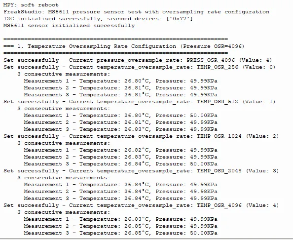
In the first stage, the fixed pressure oversampling rate is 4096, and the temperature oversampling rate is traversed within the range of 256 to 4096 to collect temperature and pressure data.
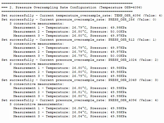
In the second stage, the fixed temperature oversampling rate is 4096, and data acquisition is performed by traversing the pressure oversampling rate within the range of 256 to 4096.
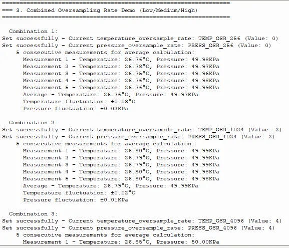
In the third phase, tests were conducted on combinations of three oversampling rates: low, medium and high. By calculating the average values and fluctuation values of temperature and pressure through 5 consecutive measurements, the characteristic that higher oversampling rate leads to smaller fluctuation of measurement data was verified.
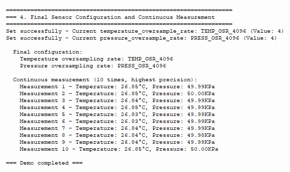
Finally, the sensor was configured to the highest precision mode with both temperature and pressure resolution set to 4096, and 10 consecutive measurements were completed, with stable data (temperature around 26.8℃, pressure around 50KPa).
IV. Drivers
ms5611_driver-1.0.1.zip 12 KB
5. BOM & Recommended Alternative Parts
None.
VI. Revision History
Document Version | Date Modified | Modifier | Modify Content |
v1.0 | 2026-03-30 | Ling Gaoxing | Initialize the document |
v1.0.1 | 2026-04-05 | Li Zisheng | The cover photo has not been taken, the production files have not been exported yet, and all other items have been sorted out. |
v1.0.2 | 2026-04-21 | Li Zisheng | The production documents have not been exported yet, and all the rest have been sorted out. |
v1.1 | 2026-04-23 | Xin Ruili | Create an open version of the document based on the internal document version v1.0.2. |
7. Relevant Materials
7.1 Chip Datasheet
MS5611.pdf 583 KB
7.2 Unique Icons for PCB Silk Screen