Contents
- I. Module Introduction
- II. Introduction to Main Chips
- 2.1 Chip Overview
- 2.2 Pin Definition
- 2.3 Functional Block Diagram
- 2.4 Performance Parameters
- 2.5 Reference Circuit
- 2.6 Chip Configuration
- 2.7 Communication Interfaces and Related Protocols
- 2.8 PCB Routing Precautions
- III. Circuit Engineering
- 3.1 Circuit Source Engineering
- 3.2 Module Usage Instructions
- 3.3 Application Experiment
- IV. Drivers
- 5. BOM & Recommended Alternative Parts
- VI. Revision History
- 7. Relevant Materials
- 7.1 Chip Datasheet
- 7.2 Unique Icons for PCB Silk Screen
I. Module Introduction
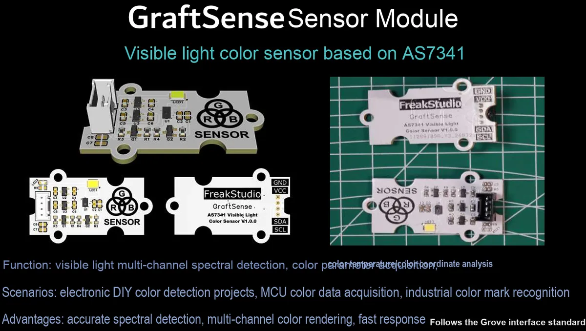
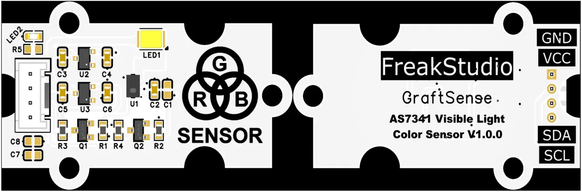
AS7341-based visible light color sensor module that adopts the AS7341 chip solution. It is a high-resolution multi-channel visible light spectrum sensor with a built-in 11-channel spectrum detection array and high-precision ADC, which can accurately measure the spectrum data and color information in the 415~940 nm band;The module integrates dual-channel LDO voltage regulators, level shifting, power filtering and I²C pull-up circuits, is equipped with fill light LED and power indicator, supports I²C communication interface, is compatible with 3.3V level MCUs, and is applicable to scenarios such as color recognition, spectral analysis, plant growth monitoring and ambient light detection.
II. Introduction to Main Chips
AS7341 is a high-resolution 11-channel visible light spectral sensor with a built-in high-precision ADC that can detect spectrum and color information in the 415~940 nm band, supports I²C interface, and is suitable for scenarios such as color recognition and spectral analysis.
2.1 Chip Overview
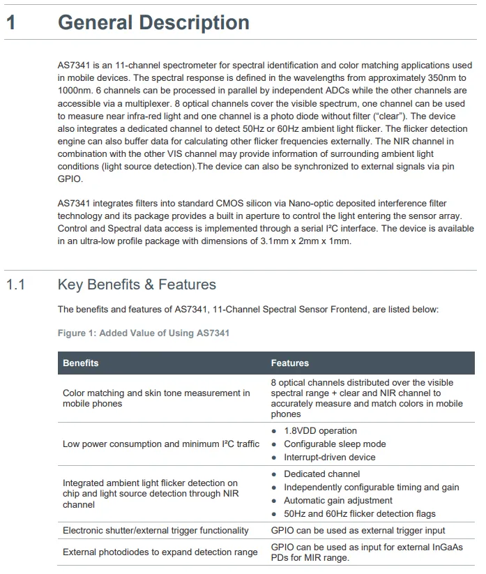
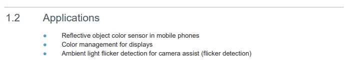
AS7341 is an 11-channel spectral sensor with a spectral response covering approximately 350nm to 1000nm, integrating 8 visible light channels, 1 near-infrared channel, 1 unfiltered channel, and 1 dedicated 50/60Hz ambient light flicker detection channel, with a built-in independent ADC and nano-optic interference filter; it communicates via the I²C interface and features an ultra-compact package of 3.1mm×2mm×1mm;Featuring low power consumption, configurable sleep mode, automatic gain, and external trigger, it is mainly applied in scenarios such as reflective object color detection for mobile phones, display color management, and camera-assisted ambient light flicker detection.
2.2 Pin Definition
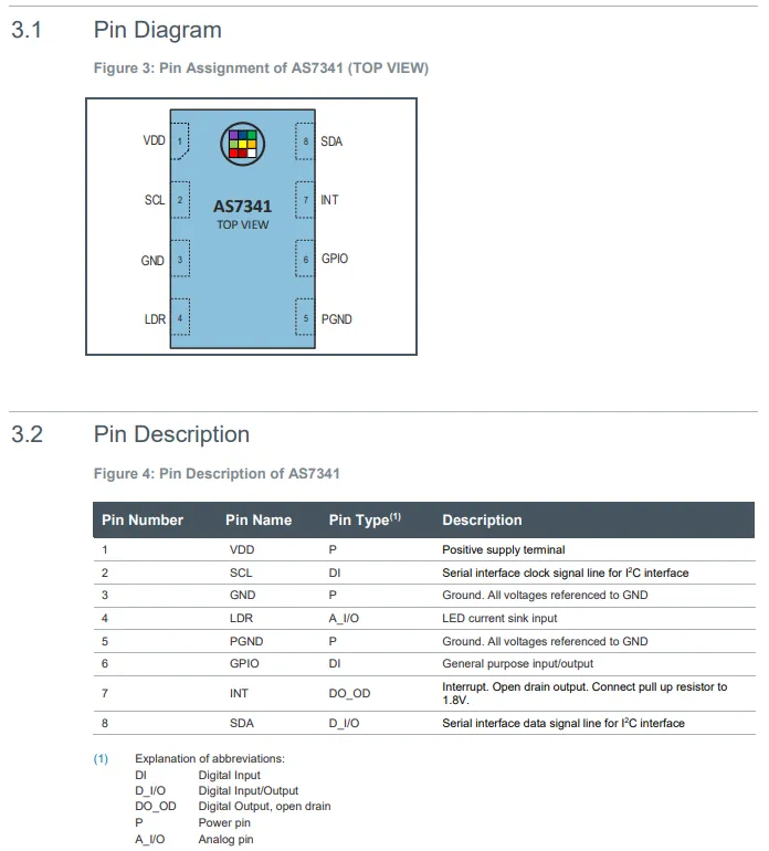
The AS7341 chip adopts an 8-pin package, with Pin 1 serving as the power supply VDD, Pins 3 and 5 as ground GND / PGND; Pins 2 (SCL) and 8 (SDA) act as the I²C communication interface, Pin 4 (LDR) functions as the LED current sinking input, Pin 6 (GPIO) is a general-purpose IO, and Pin 7 (INT) is an open-drain output interrupt pin. Meanwhile, the top-view package markings and type definitions of each pin are also provided, clearly illustrating the distribution and functions of power supply, communication, control and functional pins.
2.3 Functional Block Diagram
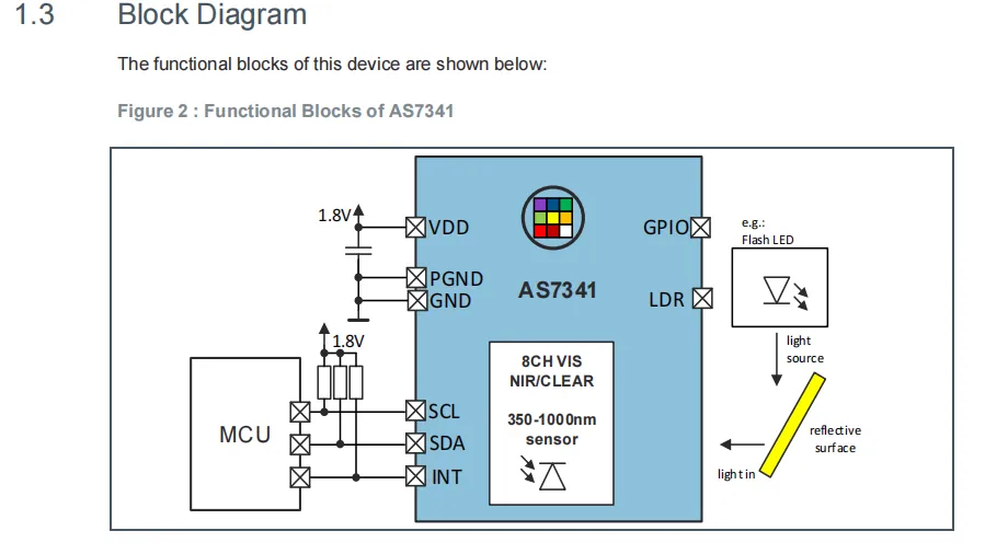
AS7341 is powered by a 1.8V power supply, and integrates an 8-channel visible light, near-infrared and filter-free spectral sensor array covering 350~1000nm, which can collect the spectral information of the reflected light from the target;LDR pin is connected to the supplementary lighting LED to provide illumination. After the collected spectral signal is processed internally, it communicates with the main control I²C interface (SCL / SDA) with the main control MCU, the INT pin outputs an interrupt signal, and the GPIO can be used for external triggering, which integrally realizes high-precision visible light spectrum and color detection, and supports ambient light flicker detection function at the same time.
2.4 Performance Parameters
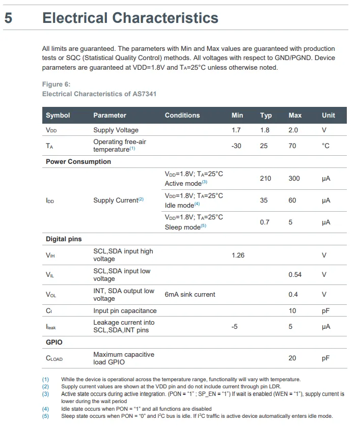
AS7341 The chip has a supply voltage range of 1.7~2.0V (typical value: 1.8V) and an operating temperature range of -30~70℃. In terms of power consumption, it features a typical active-mode current of 210μA (maximum 300μA), a typical idle-mode current of 35μA (maximum 60μA), and a sleep-mode current as low as 0.7~5μA.Regarding the digital pins, I²C interface has high and low level thresholds of 1.26V and 0.54V respectively;INT / SDA open-drain output features a maximum low level of 0.4V (at 6mA sink current), input capacitance of 10pF, and leakage current of ±5μA;GPIO supports a maximum capacitive load of 20pF, all of which collectively reflect the characteristics of low power consumption and stable digital interface.
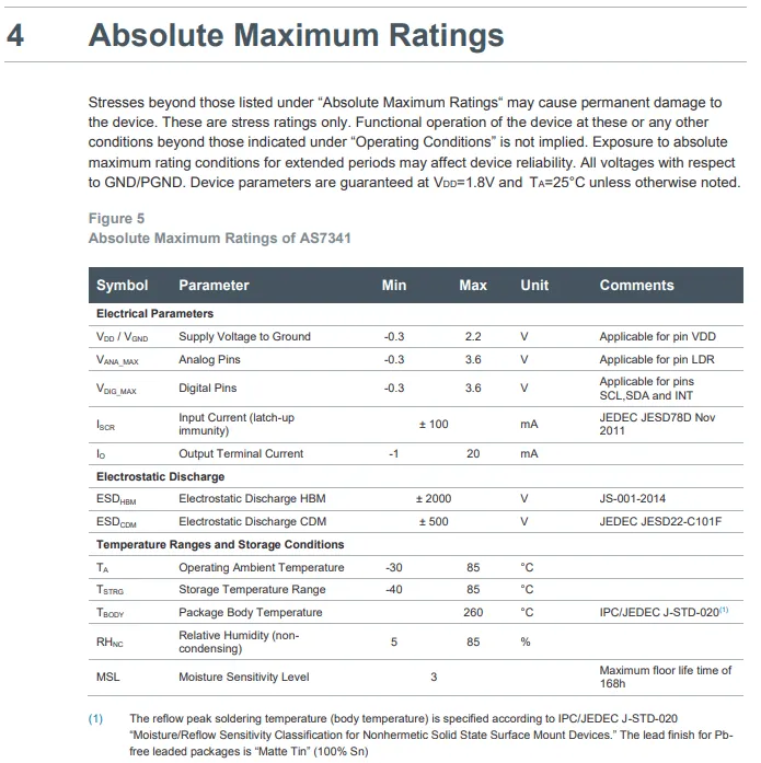
The supply voltage limit of the AS7341 's VDD pin is -0.3~2.2V, the voltage limit of analog/digital pins is -0.3~3.6V, the latch-up current is ±100mA, and the output terminal current is -1~20mA; in terms of ESD protection, the HBM mode is ±2000V, and the CDM mode is ±500V;In terms of environmental parameters, the operating temperature ranges from -30°C to 85°C, the storage temperature ranges from -40°C to 85°C, the package withstands temperatures up to 260°C, and the moisture sensitivity level is Grade 3 (with a maximum Floor Life of 168 hours), which collectively defines the chip's ultimate stress range and reliability boundaries.
2.5 Reference Circuit
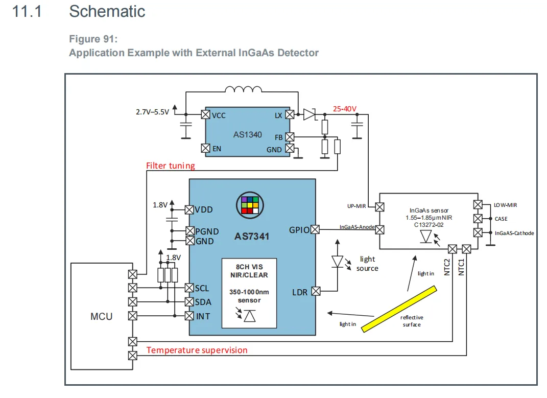
AS7341 with external InGaAs detector extended application circuit: The AS1340 boost chip provides 25-40V high voltage for filter tuning, AS7341 is powered by 1.8V, and communicates with I²C interface (SCL / SDA) to MCU, with the INT pin outputting interrupt signal;External InGaAs sensor extends the mid-infrared detection range. LDR pins are connected to the fill light source, with a reserved temperature monitoring interface, realizing an overall wide-spectrum detection from 350nm to 1.85μm, which is suitable for high-precision spectral analysis scenarios.
2.6 Chip Configuration
None.
2.7 Communication Interfaces and Related Protocols
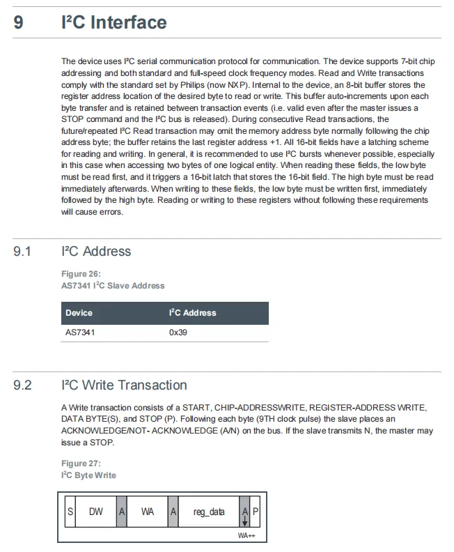
The AS7341 chip adopts I²C serial communication, supports 7-bit addressing and standard/full-speed clock modes, and has a built-in 8-bit buffer with automatic increment of register addresses; 16-bit field read and write operations must follow the order of low byte first and then high byte. Its fixed I²C slave address is 0x39. A write operation consists of a start bit, a chip address (for write), a register address, data bytes and a stop bit; the slave returns an acknowledge signal after each byte is transmitted, which overall standardizes the requirements for the address, timing and data format of I²C communication.
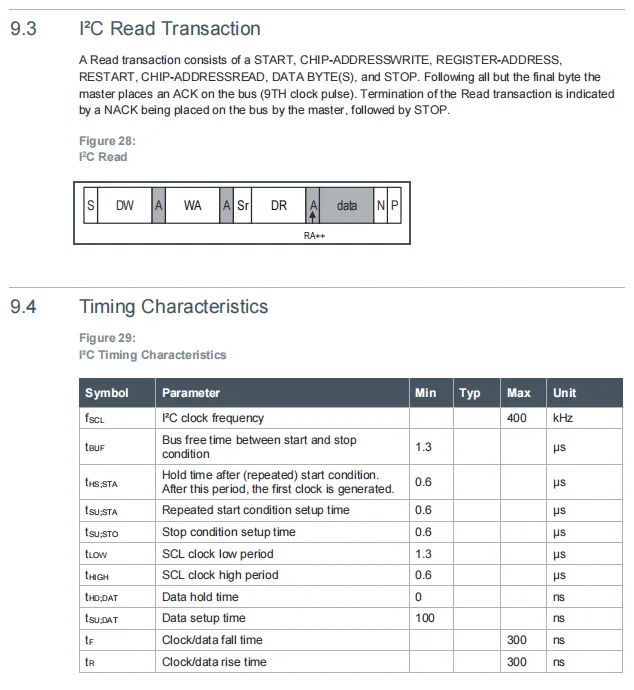
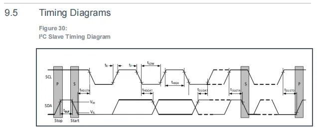
AS7341 I²C read operation and timing characteristics description: The read operation consists of a start condition, chip address (write), register address, repeated start condition, chip address (read), data bytes, and a stop condition; the master must send an acknowledge bit before the last data byte and a non-acknowledge bit at the end of the transfer, and data reading proceeds with automatic address increment.In terms of electrical timing, I²C supports a maximum clock frequency of 400kHz. For SCL, the typical duration of both high and low level cycles is 1.3μs; parameters including data hold/setup time and rise/fall time all have clear nanosecond-level limits, which ensures the stable timing and data transmission of the I²C interface communication.
2.8 PCB Routing Precautions
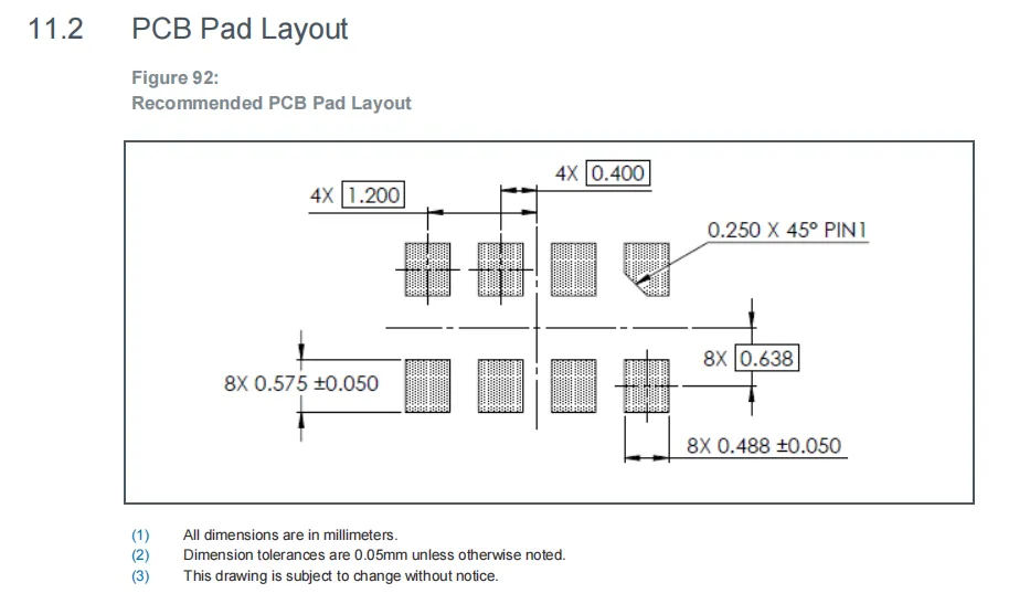
AS7341 Recommended PCB Pad Layout Design: The diagram specifies the dimensions, spacing, and quantity of each pad, all in millimeters with a default tolerance of 0.05mm; it includes the PIN1 positioning pad with a 45° chamfer, the overall layout presents a symmetrically distributed pad array on both sides, with detailed parameters for pad spacing, length, and quantity clearly marked.
III. Circuit Engineering
3.1 Circuit Source Engineering
To obtain the circuit source project, please follow the official account [Freak Embedded].
3.2 Module Usage Instructions
The schematic diagram of this module is shown below:
SCH_AS7341-based visible light color sensor-V1.0.0_2026-03-30.pdf 2.3 MB
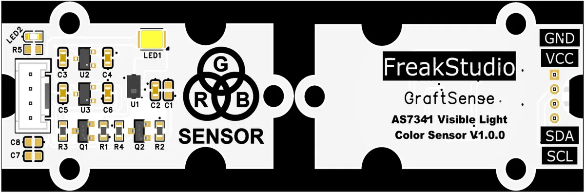
This module provides an I²C communication interface: it supports standard/full-speed I²C communication rates, with a fixed slave address of 0x39, and is compatible with 3.3V level MCUs;The module integrates dual-channel LDO voltage regulation, level shifting, power filtering and I²C pull-up circuits, is equipped with fill light LED and power indicator, and can output 11-channel visible light spectrum data processed by a high-precision ADC (covering the 415~940 nm wavelength band). It is suitable for scenarios such as color recognition, spectral analysis, plant growth monitoring and ambient light detection, providing reliable spectrum acquisition and interaction capabilities for the system.
3.3 Application Experiment
Here, we use the GraftPort-RP2040 development board for testing, and the AS7341-based visible light color sensor communicates with the main controller via the I2C interface.
Here, we first use the HY2.0-4P connection cable to connect the module to the GraftPort-RP2040 development board's I2C0 interface:
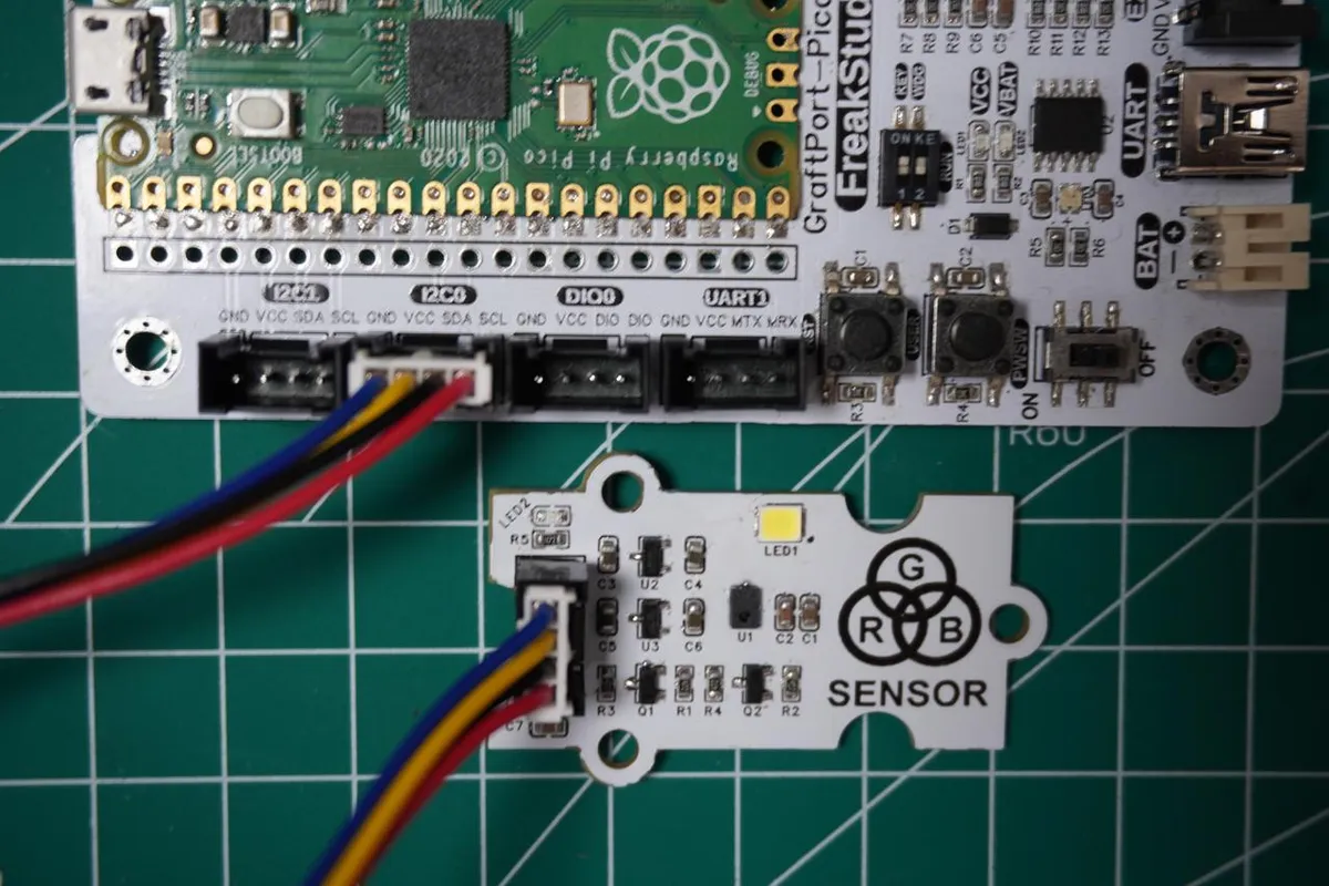
The module connections are shown in the following table:
Development Board Pins | Module Pins | Description |
Pin 4 |
|
|
Pin 5 |
|
|
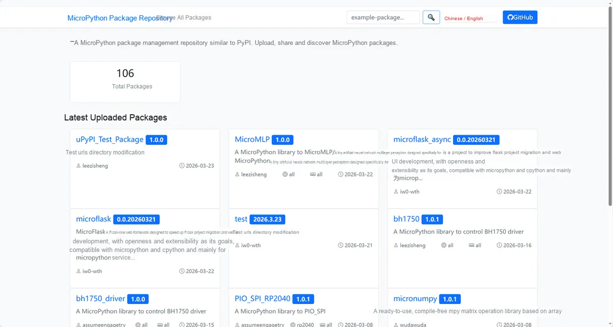
Here, we need to search for the relevant driver packages on uPyPI: https://upypi.net/zh/
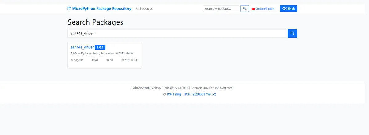
Enter as7341_driver to search, and the following will be displayed:
Click to copy the local installation command:
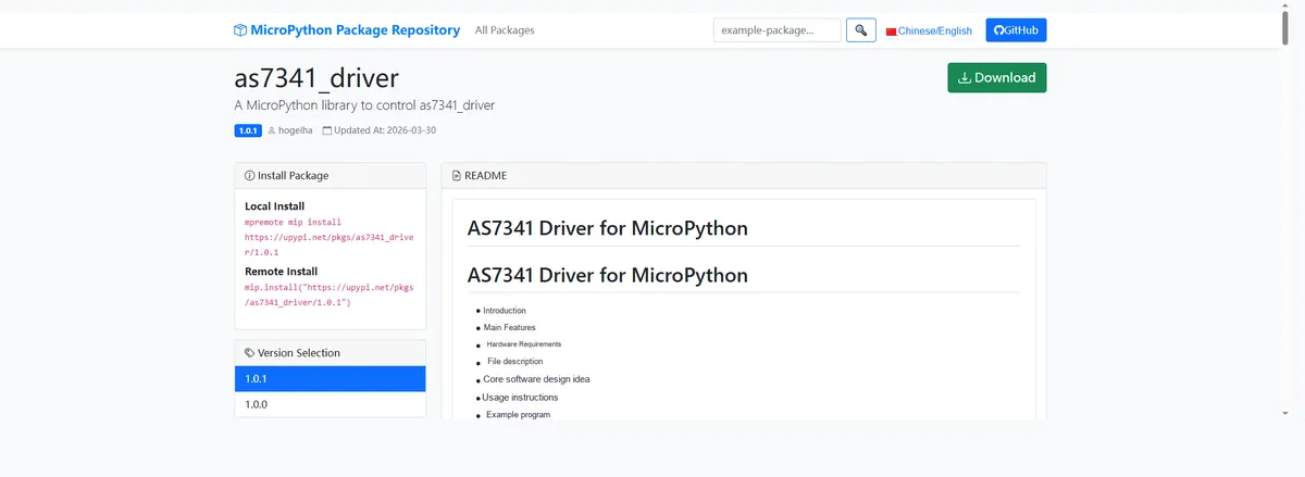
Import the module driver library code via the mip tool. Below are the usage commands for the mpremote tool:
mpremote mip install https://upypi.net/pkgs/as7341_driver/1.0.0Import the AS7341-based visible light color sensor - MicroPython driver code, then copy the following main.py code into our project:
# Python env   : MicroPython v1.23.0
# -*- coding: utf-8 -*-
# @Time    : 2026/3/12 9:00 PM
# @Author  : hogeiha
# @File    : main.py
# @Description : Raspberry Pi Pico drives the AS7341 spectral sensor: configure parameters, read spectral data, control LED and GPIO, configure interrupts + newly added color recognition function

# ======================================== Import Modules =========================================

import sys
import time
from machine import I2C, Pin

# Import the AS7341 driver and create the sensor object
from as7341 import AS7341

# ======================================== Global Variables ============================================

# ======================================== Functions ============================================


# Initialize the I2C bus
def init_i2c():
    """
    Initialize the I2C bus
    Args: None

    Raises: None

    Notes: Applies to the RP2040 platform; pin definitions must be changed for other boards

    ==========================================
    Initialize I2C bus
    Args:None

    Raises:None

    Notes:Adapted for RP2040 platform, modify pin definitions for other boards
    """
    try:
        # Create the I2C0 object, SCL=5, SDA=4, frequency 100kHz
        i2c = I2C(0, scl=Pin(5), sda=Pin(4), freq=100000)
        # Scan all devices on the I2C bus
        detected_devices = [hex(addr) for addr in i2c.scan()]
        # Print the detected device addresses
        print(f"I2C initialization successful, detected device addresses: {', '.join(detected_devices)}")
        # Check whether the AS7341 sensor is online (default address 0x39)
        if "0x39" not in detected_devices:
            print("Warning: AS7341 sensor not detected (default address 0x39)")
        return i2c
    except Exception as e:
        print(f"I2C initialization failed: {e}")
        return None


# Print separator line title
def print_separator(title):
    """
    Print separator line title
    Args:title: Title text to display

    Raises: None

    Notes: Improves output readability

    ==========================================
    Print separator title
    Args:title: Title text to display

    Raises:None

    Notes:Improve output readability
    """
    print("\n" + "=" * 70)
    print(f"=== {title}")
    print("=" * 70)


# Safely execute function
def safe_execute(func, *args, desc="operation"):
    """
    Safely execute a function and catch exceptions
    Args:func: Function to execute
         *args: Function arguments
         desc: Operation description

    Raises: None

    Notes: None

    ==========================================
    Safely execute function and catch exceptions
    Args:func: Function to execute
         *args: Function arguments
         desc: Operation description

    Raises:None

    Notes:None
    """
    try:
        result = func(*args)
        return result, True
    except Exception as e:
        print(f"  Operation {desc} failed: {e}")
        return None, False


# Convert spectral data to RGB values
def spectrum_to_rgb(f1, f2, f3, f4, f5, f6, f7, f8):
    """
    Convert AS7341 8-channel spectral data to RGB values
    Args:f1-f8: Raw data of the 8 spectral channels

    Raises: None

    Notes:Channel mapping: F1 (violet), F2 (blue), F3 (cyan), F4 (green), F5 (yellow-green), F6 (yellow-orange), F7 (orange-red), F8 (red)

    ==========================================
    Convert AS7341 8-channel spectral data to RGB values
    Args:f1-f8: Raw data from 8 spectral channels

    Raises:None

    Notes:Channel mapping: F1(Violet), F2(Blue), F3(Cyan), F4(Green), F5(Green-Yellow), F6(Yellow-Orange), F7(Orange-Red), F8(Red)
    """
    # Get the maximum value of all channels for normalization
    max_val = max(f1, f2, f3, f4, f5, f6, f7, f8)
    if max_val == 0:
        return (0, 0, 0)

    # Assign RGB weights by wavelength: the red channel uses F7 and F8
    r = (f7 + f8 * 1.2) / max_val * 255
    # The green channel uses F4 and F5
    g = (f4 + f5 * 1.1) / max_val * 255
    # The blue channel uses F2 and F3
    b = (f2 + f3 * 0.9) / max_val * 255

    return (int(r), int(g), int(b))


# Get the color name from the RGB values
def get_color_name(r, g, b):
    """
    Identify the color name from the RGB values
    Args:r: Red component (0-255)
         g: Green component (0-255)
         b: Blue component (0-255)

    Raises: None

    Notes:The color recognition thresholds can be adjusted according to the actual lighting conditions

    ==========================================
    Get color name based on RGB values
    Args:r: Red component (0-255)
         g: Green component (0-255)
         b: Blue component (0-255)

    Raises:None

    Notes:Color recognition threshold can be adjusted based on actual lighting conditions
    """
    threshold = 40
    # Check whether it is black / no light
    if r < threshold and g < threshold and b < threshold:
        return "Black/No Light"
    # Check whether it is white
    elif r > 200 and g > 200 and b > 200:
        return "White"
    # Check whether it is red
    elif r > g + 50 and r > b + 50:
        return "Red"
    # Check whether it is green
    elif g > r + 50 and g > b + 50:
        return "Green"
    # Check whether it is blue
    elif b > r + 50 and b > g + 50:
        return "Blue"
    # Check whether it is yellow
    elif r > 150 and g > 150 and b < 100:
        return "Yellow"
    # Check whether it is purple
    elif r > 150 and b > 150 and g < 100:
        return "Purple"
    # Check whether it is cyan
    elif g > 150 and b > 150 and r < 100:
        return "Cyan"
    # Check whether it is orange
    elif r > g and g > b:
        return "Orange"
    else:
        return "Mixed Color"


# ======================================== Custom Classes ============================================

# ======================================== Initialization configuration ===========================================

# Delay 3 seconds to wait for the hardware to stabilize
time.sleep(3)
print("FreakStudio: AS7341 spectral sensor configuration and measurement demonstration on Raspberry Pi Pico")

# Initialize the I2C bus
i2c = init_i2c()
if not i2c:
    sys.exit(1)

sensor = AS7341(i2c)

# Check the sensor connection status
if not sensor.isconnected():
    print("Failed to connect to AS7341 sensor, program exited")
    sys.exit(1)
print("AS7341 sensor initialized successfully!")

# ========================================  Main Program  ============================================

# 1. Basic configuration demo (integration time, gain, measurement mode)
print_separator("1. Basic parameter configuration demonstration")

# 1.1 Set the integration time (ASTEP + ATIME)
print("\n  [Integration time configuration]")
# Set the ASTEP step value to 599
sensor.set_astep(599)
astep_time = sensor.get_astep_time()
print(f"    ASTEP set value: 599 -> step time: {astep_time:.3f} ms")

# Set the ATIME integration step count to 29
sensor.set_atime(29)
int_time = sensor.get_integration_time()
overflow_count = sensor.get_overflow_count()
print(f"    ATIME set value: 29 -> total integration time: {int_time:.2f} ms")
print(f"    Maximum count value: {overflow_count}")

# 1.2 Set the gain (AGAIN)
print("\n  [Gain configuration]")
# Set via gain code (code 4 corresponds to 8x gain)
sensor.set_again(4)
gain_code = sensor.get_again()
gain_factor = sensor.get_again_factor()
print(f"    Gain code set to 4 -> actual gain code: {gain_code}, gain factor: {gain_factor}x")

# Set via gain multiplier (automatically converted to the corresponding code)
sensor.set_again_factor(16)
gain_code2 = sensor.get_again()
gain_factor2 = sensor.get_again_factor()
print(f"    Gain factor set to 16 -> actual gain code: {gain_code2}, gain factor: {gain_factor2}x")

# 1.3 Set the measurement mode to SPM single-pulse mode
sensor.set_measure_mode(AS7341.AS7341_MODE_SPM)
print("\n  Measurement mode set to SPM (single pulse mode)")
time.sleep(1)

# 2. Spectral measurement demo (all preset channel mappings)
print_separator("2. Spectral measurement demonstration (all channels)")

# Define the channel mapping description dictionary
channel_maps = {
    "F1F4CN": "F1(405-425nm), F2(435-455nm), F3(470-490nm), F4(505-525nm), CLEAR, NIR",
    "F5F8CN": "F5(545-565nm), F6(580-600nm), F7(620-640nm), F8(670-690nm), CLEAR, NIR",
    "F2F7": "F2(435-455nm), F3(470-490nm), F4(505-525nm), F5(545-565nm), F6(580-600nm), F7(620-640nm)",
    "F3F8": "F3(470-490nm), F4(505-525nm), F5(545-565nm), F6(580-600nm), F7(620-640nm), F8(670-690nm)",
}

# Iterate over all preset channel mappings and measure
for map_name, desc in channel_maps.items():
    print(f"\n  Measurement channel: {map_name} -> {desc}")
    # Start measurement and specify the channel mapping
    sensor.start_measure(map_name)
    # Get the spectral data
    data, success = safe_execute(sensor.get_spectral_data, desc=f"read {map_name} data")
    if success and data:
        # Format the output according to the channel mapping
        if map_name == "F1F4CN":
            f1, f2, f3, f4, clr, nir = data
            print(f"    F1: {f1:6d} | F2: {f2:6d} | F3: {f3:6d} | F4: {f4:6d} | CLEAR: {clr:6d} | NIR: {nir:6d}")
        elif map_name == "F5F8CN":
            f5, f6, f7, f8, clr, nir = data
            print(f"    F5: {f5:6d} | F6: {f6:6d} | F7: {f7:6d} | F8: {f8:6d} | CLEAR: {clr:6d} | NIR: {nir:6d}")
        elif map_name == "F2F7":
            f2, f3, f4, f5, f6, f7 = data
            print(f"    F2: {f2:6d} | F3: {f3:6d} | F3: {f3:6d} | F5: {f5:6d} | F6: {f6:6d} | F7: {f7:6d}")
        elif map_name == "F3F8":
            f3, f4, f5, f6, f7, f8 = data
            print(f"    F3: {f3:6d} | F4: {f4:6d} | F5: {f5:6d} | F6: {f6:6d} | F7: {f7:6d} | F8: {f8:6d}")
    time.sleep_ms(500)

# 3. Single-channel data reading demo
print_separator("3. Single channel data reading demonstration")
# First switch to the F1F4CN mapping
sensor.start_measure("F1F4CN")
for ch in range(6):
    ch_data = sensor.get_channel_data(ch)
    ch_names = ["F1", "F2", "F3", "F4", "CLEAR", "NIR"]
    print(f"  Channel {ch} ({ch_names[ch]}): {ch_data}")

# 4. Onboard LED control demo
print_separator("4. On-board LED control demonstration")
# Available LED current values: 4, 8, 12, 16, 20 mA
led_currents = [4, 8, 12, 16, 20]
for curr in led_currents:
    sensor.set_led_current(curr)
    print(f"  Set LED current: {curr} mA (on for 2 seconds)")
    time.sleep(2)

# Turn off the LED
sensor.set_led_current(0)
print("  LED turned off")

# 6. GPIO pin control demo
print_separator("6. GPIO pin control demonstration")
# Configure the GPIO as output mode (normal mode)
sensor.set_gpio_output(inverted=False)
print("  GPIO configured as output mode (normal) -> LED on (if connected)")
time.sleep(1)

# Invert the GPIO output
sensor.set_gpio_inverted(True)
print("  GPIO output inverted -> LED off (if connected)")
time.sleep(1)

# Configure the GPIO as input mode
sensor.set_gpio_input(enable=True)
gpio_value = sensor.get_gpio_value()
print(f"  GPIO configured as input mode -> current GPIO value: {gpio_value} (True=high, False=low)")

# 7. Interrupt configuration demo
print_separator("7. Interrupt configuration demonstration")
# Set the spectral interrupt thresholds (low threshold 1000, high threshold 10000)
sensor.set_thresholds(1000, 10000)
lo_th, hi_th = sensor.get_thresholds()
print(f"  Set spectral interrupt thresholds -> low threshold: {lo_th}, high threshold: {hi_th}")

# Set the interrupt persistence (trigger after 3 consecutive threshold crossings)
sensor.set_interrupt_persistence(3)
print("  Set interrupt persistence: 3")

# Enable the spectral interrupt
sensor.set_spectral_interrupt(True)
print("  Enabled spectral interrupt")

# Check and clear the interrupt
interrupt_status = sensor.check_interrupt()
print(f"  Current interrupt status: {interrupt_status}")
sensor.clear_interrupt()
print("  Cleared all interrupts")

# 8. Auto-restart configuration demo (WTIME)
print_separator("8. Auto restart (WTIME) configuration demonstration")
# Set the WTIME auto-restart interval to 99
sensor.set_wtime(99)
# Enable the auto-restart function
sensor.set_wen(True)
print("  Set WTIME=99 -> auto restart interval ~278ms, WEN enabled")

print_separator("9. Color Recognition Demonstration")

# Read the complete 8-channel spectral data
try:
    while True:
        # Read the F1-F4 and CLEAR, NIR channel data
        sensor.start_measure("F1F4CN")
        f1, f2, f3, f4, _, _ = sensor.get_spectral_data()
        # Read the F5-F8 and CLEAR, NIR channel data
        sensor.start_measure("F5F8CN")
        f5, f6, f7, f8, _, _ = sensor.get_spectral_data()

        # Print the raw spectral data
        print(f"\n  8-channel raw data: F1={f1}, F2={f2}, F3={f3}, F4={f4}")
        print(f"                    F5={f5}, F6={f6}, F7={f7}, F8={f8}")

        # Convert to RGB values
        rgb = spectrum_to_rgb(f1, f2, f3, f4, f5, f6, f7, f8)
        color_name = get_color_name(rgb[0], rgb[1], rgb[2])

        # Output the recognition result
        print(f"  Converted RGB values: R={rgb[0]}, G={rgb[1]}, B={rgb[2]}")
        print(f"  Recognition result: 【 {color_name} 】")

        time.sleep(1)

except Exception as e:
    print(f"  Color recognition failed: {e}")
In the code above, we drive the AS7341 spectral sensor via the I2C bus. After completing the sensor connection check, we sequentially configure core parameters such as integration time, gain, and measurement mode, iterate through all channel mappings to read full-band spectral data and test single-channel reading, meanwhile implement on-board LED current adjustment and GPIO pin input/output control, and also complete the configuration and verification of the spectral interrupt threshold, trigger persistence, and auto-restart functions. Finally, we power off the sensor, comprehensively demonstrating the parameter configuration, Data Acquisition, peripheral control and interrupt functions of this spectral sensor.
Burn the code, open the terminal, and the output is as follows:
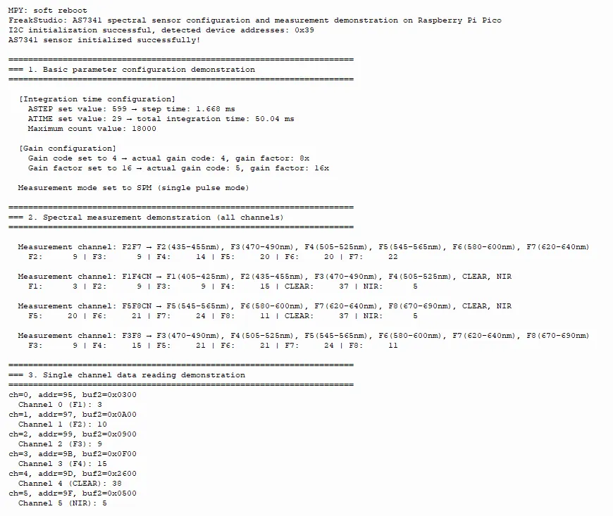
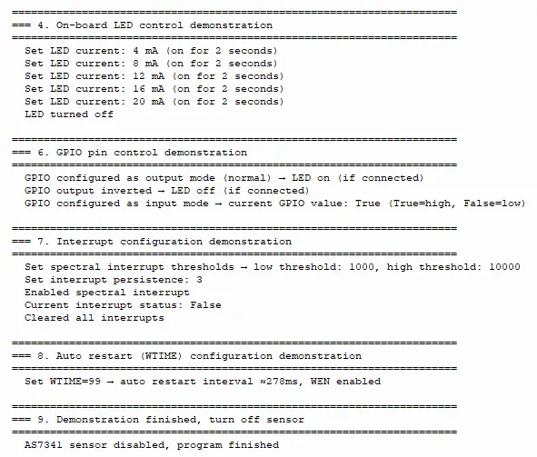
This test is conducted under indoor ambient light conditions (without standard color patches or specific light sources). Therefore, the raw count values of all visible light channels (F1 - F8), CLEAR, and NIR channels are generally low as a completely normal phenomenon — the sensor only responds to the actual light intensity of the corresponding wavelength band present in the environment, and naturally exhibits low counts when not excited by highly saturated light sources. For subsequent applications such as color recognition and spectral analysis, simply pairing with a standard light source or highly saturated test patches will yield high-response data for the corresponding wavelength bands, giving full play to the sensor's multispectral detection capability.
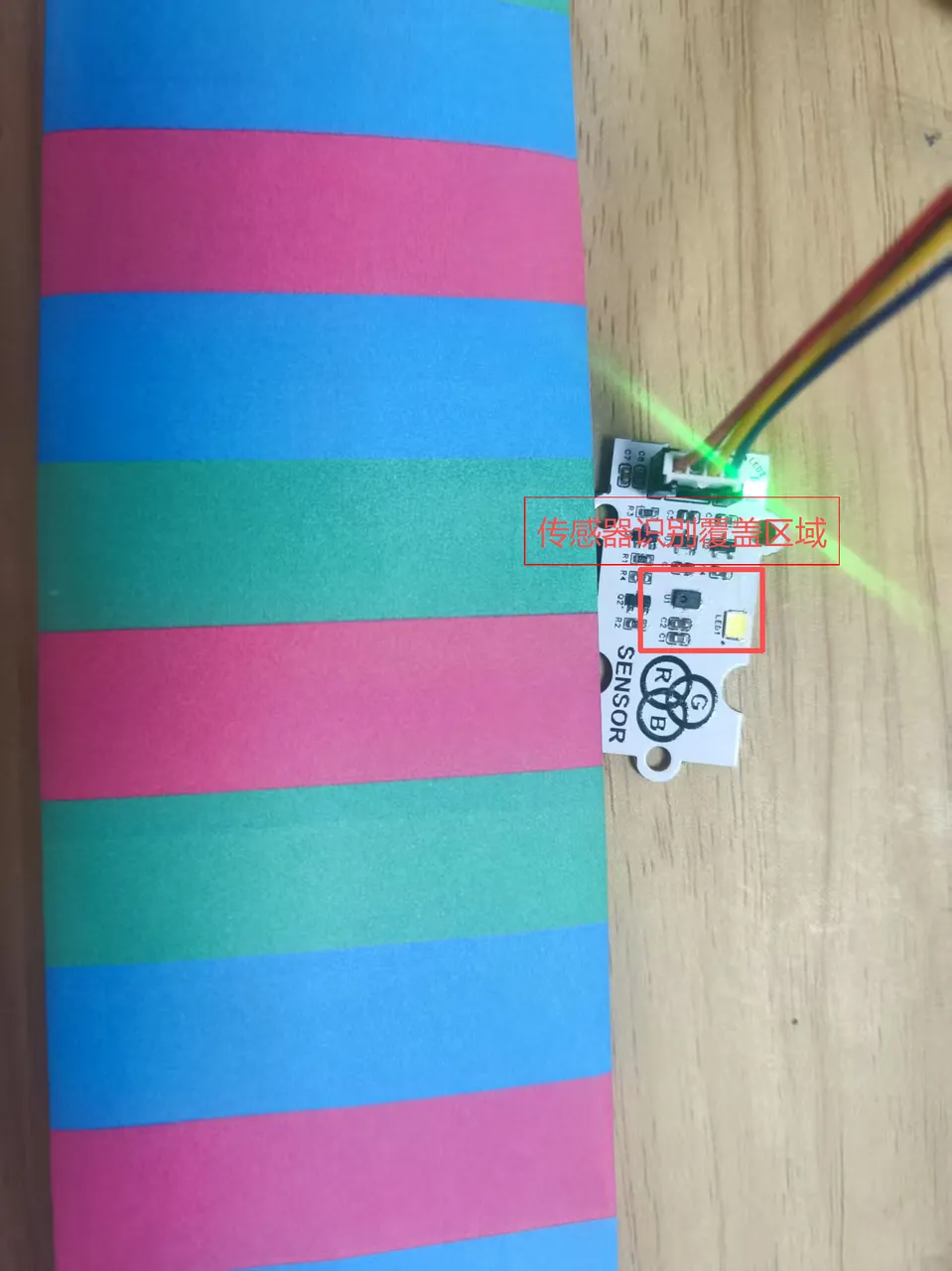
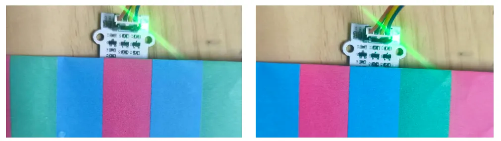
Using the color card to cover the sensor identification area according to the above figure, the output is as follows:
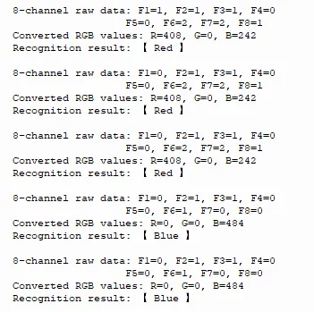
8-channel original spectral data is detected, RGB conversion values are calculated, and the color is identified. The color recognition function is implemented through simple analysis based solely on the spectral data collected by the sensor.
IV. Drivers
as7341_driver-1.0.1.zip 20 KB
5. BOM & Recommended Alternative Parts
None.
VI. Revision History
Document Version | Date Modified | Modifier | Modify Content |
v1.0 | 2026-03-30 | Ling Gaoxing | Initialize the document |
v1.0.1 | 2026-04-05 | Li Zisheng | The cover photo has not been taken, the production files have not been exported yet, and all other items have been sorted out. |
v1.0.2 | 2026-04-14 | Li Zisheng | Modified main.py. |
v1.0.3 | 2026-04-21 | Li Zisheng | The production documents have not been exported yet, and all the rest have been sorted out. |
v1.1 | 2026-04-23 | Xin Ruili | Create an open version of the document, based on the internal document version v1.0.3. |
7. Relevant Materials
7.1 Chip Datasheet
AS7341.pdf 1.5 MB
7.2 Unique Icons for PCB Silk Screen