Contents
- I. Module Introduction
- II. Introduction to Main Chips
- 2.1 Chip Overview
- 2.2 Pin Definition
- 2.3 Functional Block Diagram
- 2.4 Performance Parameters
- 2.5 Reference Circuit
- 2.6 Chip Configuration
- 2.7 Communication Interfaces and Related Protocols
- 2.8 PCB Routing Precautions
- III. Circuit Engineering
- 3.1 Circuit Source Engineering
- 3.2 Module Usage Instructions
- 3.3 Application Experiment
- IV. Drivers
- 5. BOM & Recommended Alternative Parts
- VI. Revision History
- 7. Relevant Materials
- 7.1 Chip Datasheet
- 7.2 Unique Icons for PCB Silk Screen
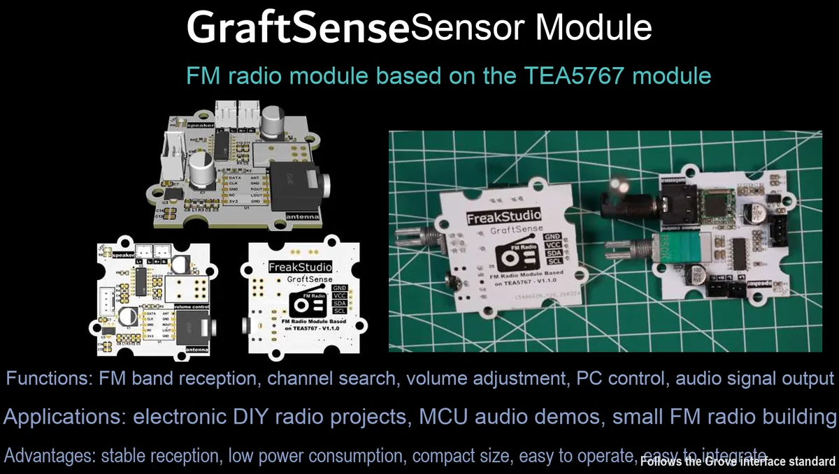
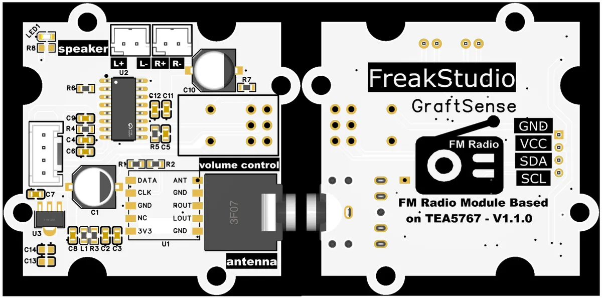
I. Module Introduction
FM Radio Module Based on TEA5767, which adopts the TEA5767 + PAM8403 chip solution, is a highly integrated stereo FM radio module. It has a built-in I²C control interface and 3W + 3W Class D audio power amplifier circuit, and supports the 76~108MHz FM broadcast band;This module integrates a power filter circuit, a volume potentiometer and a power switch into a single unit. It can drive a 4Ω speaker with a single 5V power supply, and is compatible with MCUs of 3.3V level. It supports digital frequency adjustment and channel switching via I²C commands, making it ideal for audio playback scenarios such as portable radios, smart speakers and campus broadcasting systems.
II. Introduction to Main Chips
TEA5767 is a I²C -controlled stereo FM radio chip that covers the 76~108MHz frequency band, supports automatic station search and stereo output, operates on a single 5V power supply, and is designed specifically for portable FM radio devices.
2.1 Chip Overview
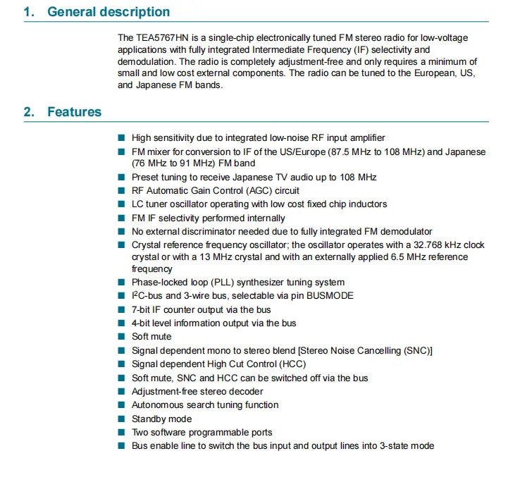
TEA5767HN is a monolithic electronically tuned FM stereo radio designed for low-voltage applications. It integrates complete intermediate frequency selectivity and demodulation functions, requires no adjustment and only a small number of low-cost peripheral components, and can cover FM frequency bands such as those for Europe and the United States (87.5~108MHz) and Japan (76~91MHz);Core features include high sensitivity with integrated low noise RF input amplifier, RF Automatic Gain Control ( AGC ), built-in intermediate frequency selectivity, no need for external frequency discriminator, 32.768kHz/13MHz crystal oscillator or 6.5MHz external reference crystal oscillator, PLL frequency synthesis tuning system, supporting I ² C or 3-wire bus control, soft mute, stereo noise cancellation ( SNC ), high frequency switch control ( HCC ), automatic search, standby mode, and two software programmable terminals Port and bus enable line.
2.2 Pin Definition
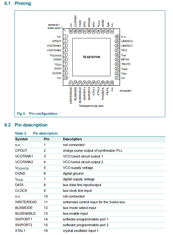
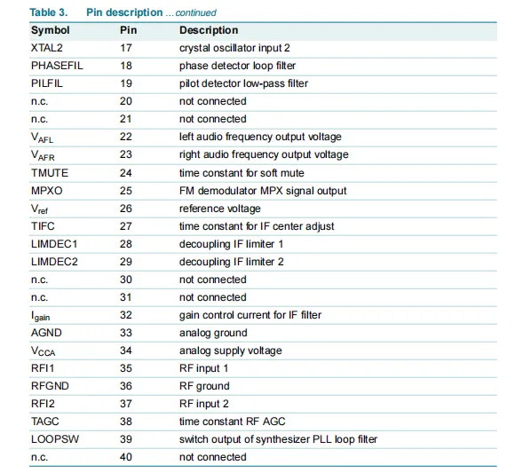
TEA5767HN chip pins are divided into multiple functional groups: including PLL phase-locked loop related charge pump output (CPOUT), VCO tuning circuit output (VCOTANK 1/2) and loop filter pins, digital/analog power and ground pins (VCC (VCO), DGND, VCCD, VCCA, AGND), I²C / 3-wire bus communication pins (DATA, CLOCK, WRITE / READ, BUSMODE, BUSENABLE), software programmable ports (SWPORT1/2), crystal oscillator input (XTAL1/2), audio output pins (VAFL, VAFR), FM demodulation and filtering related pins (MPXO, PILFIL, PHASEFIL, TIFC, LIMDEC1/2 etc.), RF signal input (RFI1/2, RFGND) and AGC related pins (TAGC, Igain), as well as multiple no-connection pins (n.c.), fully covering the hardware interfaces of all functional modules such as power supply, communication, tuning, signal processing and audio output.
2.3 Functional Block Diagram
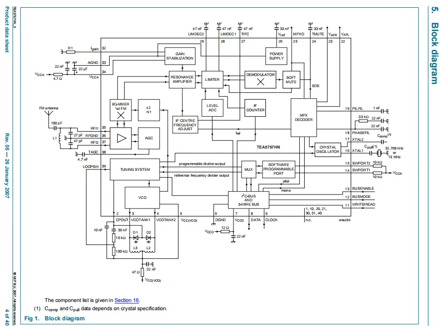
TEA5767 's FM antenna receives radio frequency signals, which are amplified by the RF input stage and then fed into the IQ mixer, where they are mixed with the local oscillator signal generated by the voltage-controlled oscillator (VCO) to obtain an intermediate frequency signal. After being limited and sampled by the level ADC, the intermediate frequency signal is sent to the demodulator; the demodulated signal then undergoes soft mute and MPX stereo decoding processing, and finally outputs left and right channel audio;At the same time, the I²C bus interface receives control instructions, and realizes frequency selection and automatic channel searching through the tuning system and programmable frequency divider; the on-chip integrated LDO regulator, gain stabilization module and AGC circuit ensure a stable operating state of low power consumption, high sensitivity and low noise.
2.4 Performance Parameters
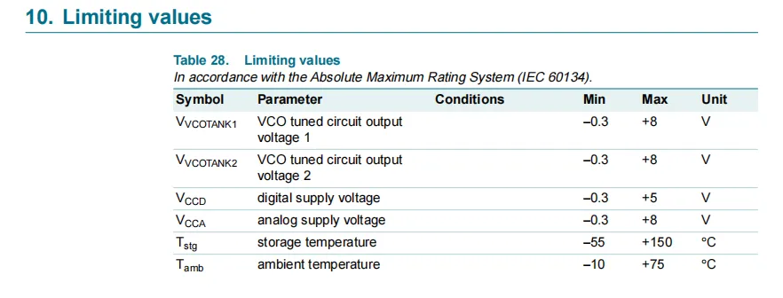
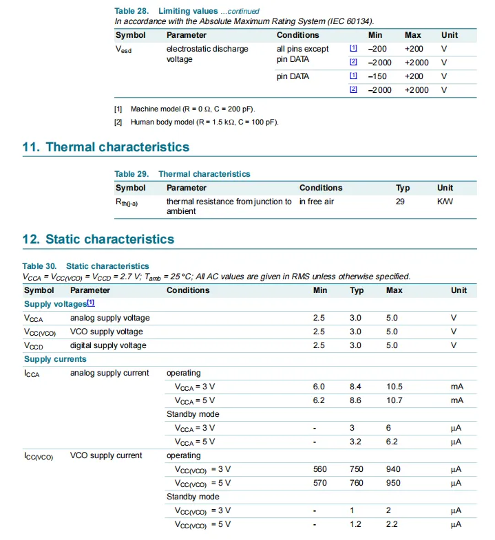
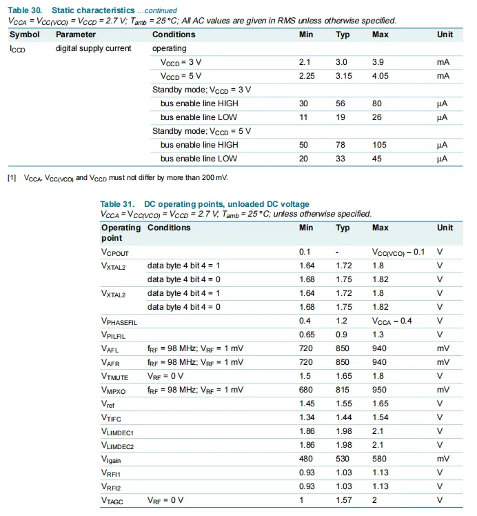
TEA5767HN complies with the IEC 60134 standard for limiting parameters. The output voltage range of the VCO tuning circuit is -0.3 to + 8V, the digital supply voltage range is -0.3 to + 5V, the analog supply voltage range is -0.3 to + 8V, the storage temperature range is -55 to + 150°C, and the operating ambient temperature range is -10 to + 75°C. ESD protection reaches ±200V or ±2000V respectively for different pins and models; the typical value of junction-to-ambient thermal resistance in thermal characteristics is 29K/W.Under static characteristics, it is recommended that the analog supply voltage, VCO and digital supply voltage all range from 2.5 V to 5.0 V (with a voltage difference of no more than 200 mV among the three); the operating current varies with the supply voltage, and the standby current is only at the microampere level. Meanwhile, the no-load DC voltage range of each pin is specified, providing complete electrical constraints and performance references for circuit design.
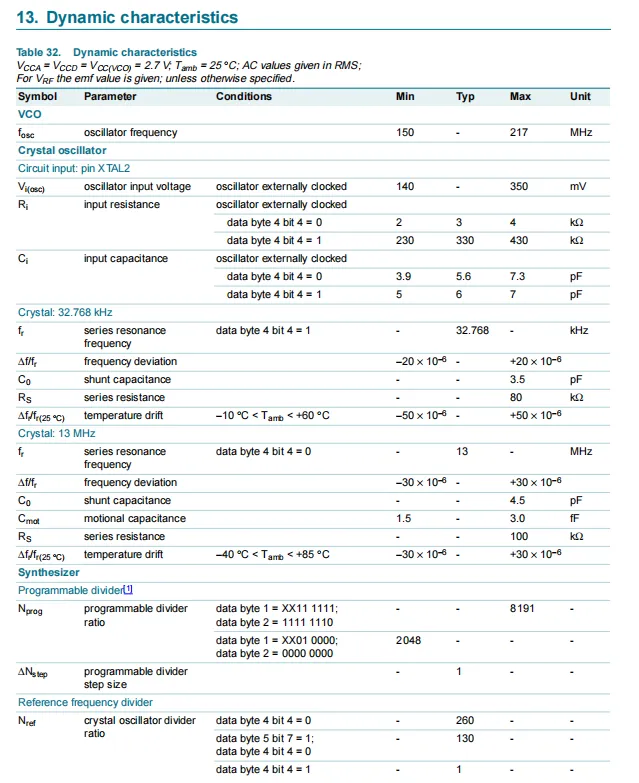
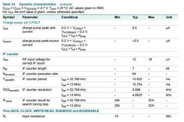
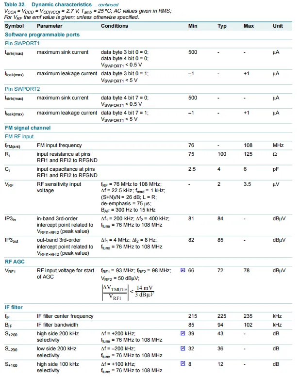
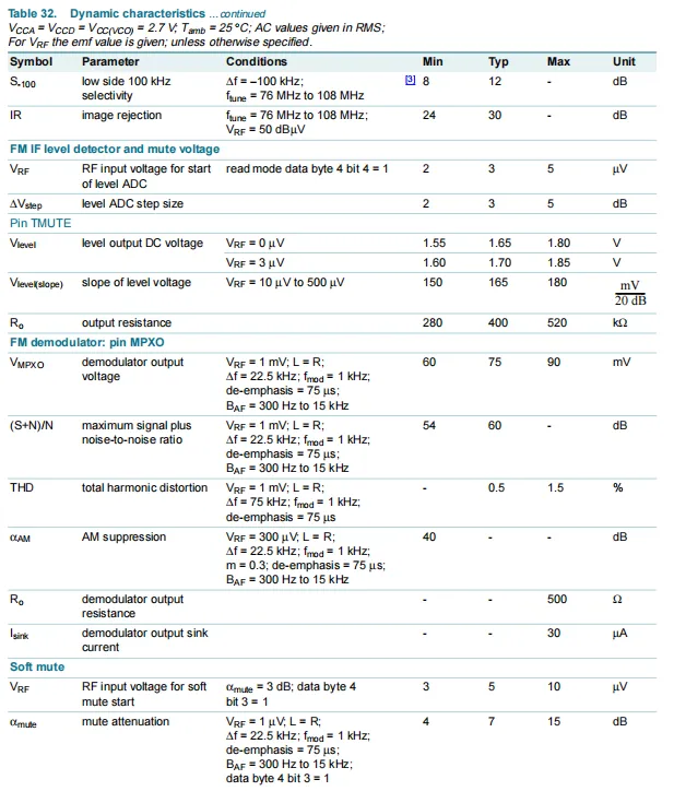
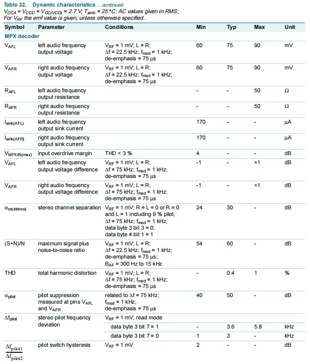
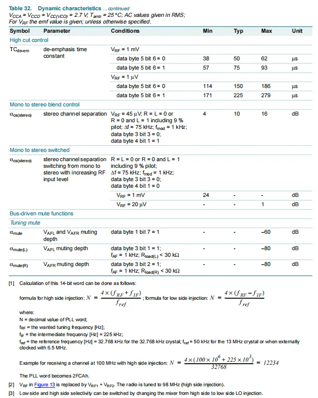
TEA5767HN features dynamic electrical characteristics that cover the entire signal chain from RF input to audio output: VCO oscillation frequency ranges from 150 to 217MHz, supports two crystal oscillators of 32.768kHz and 13MHz, the frequency synthesizer has a frequency division step of 1; the charge pump has a peak current of ±0.5μA, IF counter is 7-bit, RF reception sensitivity has a typical value of 2μV, with high selectivity and mirror rejection capability;After audio demodulation, it outputs left and right channel stereo, with total harmonic distortion < 1% and a typical channel separation of 30dB; it also integrates functions including soft mute, stereo noise cancellation(SNC), and high-frequency cut control (HCC). The bus interface has an input impedance of 10MΩ, and the maximum sink current of the software-programmable port is 500μA, providing comprehensive dynamic performance parameter support for the high sensitivity, low noise, and high-quality audio output of FM radio reception.
2.5 Reference Circuit
None.
2.6 Chip Configuration
None.
2.7 Communication Interfaces and Related Protocols
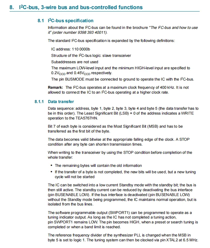
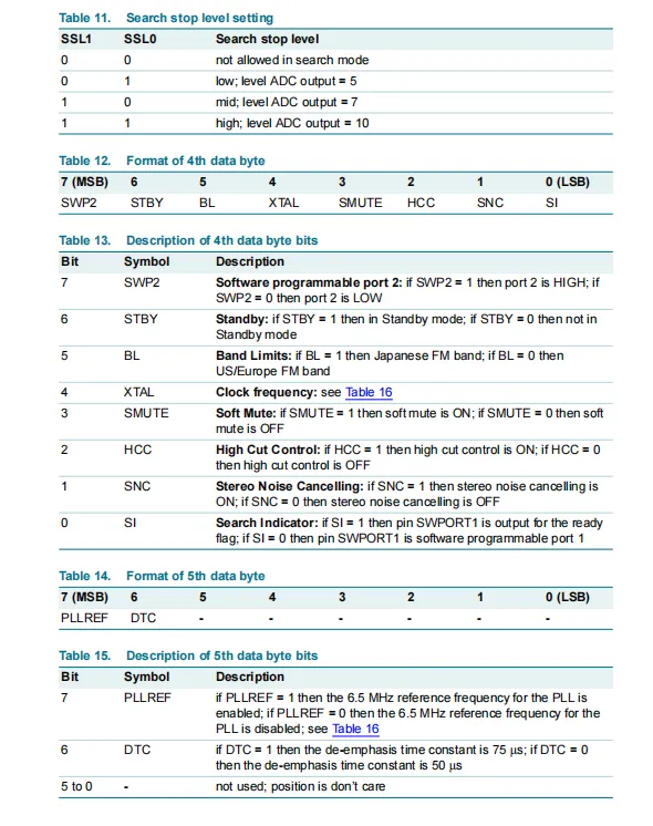
TEA5767HN chip I²C slave address is fixed at 110 0000b. The BUSMODE pin must be grounded to enable I²C mode, and the maximum clock frequency of the bus is 400kHz; the data transmission sequence is address + 5 bytes of data, the least significant bit of the address being 0 indicates a write operation, the most significant bit of each byte is transmitted first, and the data is valid on the falling edge of the clock.supports premature transmission termination upon meeting the STOP condition, can enter the low-power standby mode via the standby bit, and can output a tuning status indication through the SWPORT1 pin; meanwhile, it allows switching the reference frequency division ratio via configuration byte 5, providing a complete bus communication specification for the digital control of FM radio reception.
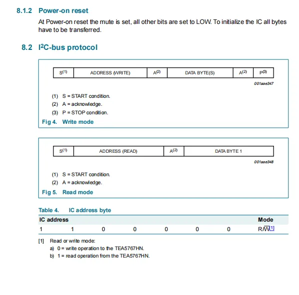
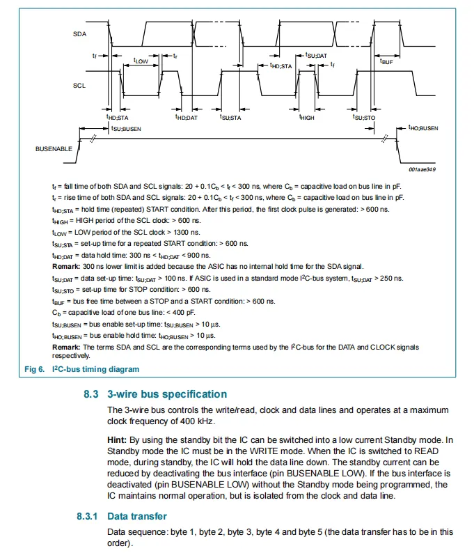
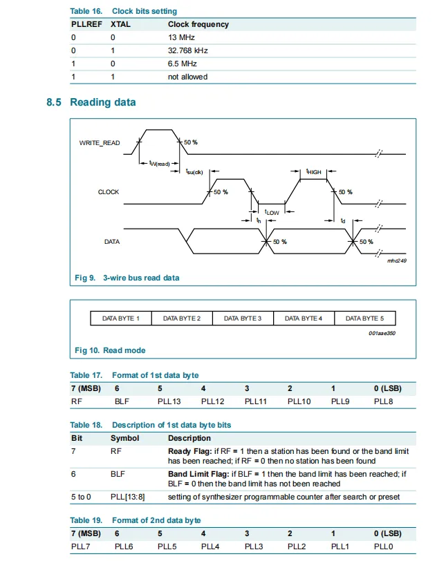
TEA5767HN The mute bit is set upon power-on reset, all other register bits are cleared, and a full 5-byte data transmission is required to complete initialization;I²C bus fixed slave address is 110 0000b, where the least significant bit R/W= 0 denotes write operation and 1 denotes read operation; the write mode follows the sequence START + address (write) + acknowledge + data + acknowledge + STOP, and the read mode follows START + address (read) + acknowledge + data; the timing specifications define constraints including setup/hold time and rise/fall time for SDA / SCL, with a maximum clock frequency of 400kHz;3-wire bus also supports a maximum clock frequency of 400kHz, can enter a low-power mode via the standby bit, and features a fixed data transmission sequence of 5 bytes, providing a complete bus communication and timing specification for the digital control of the chip.
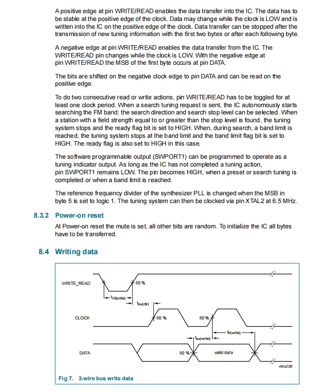
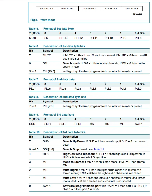
TEA5767HN 3-wire bus data transmission, power-on reset and write data format description: The 3-wire bus controls data transmission and reception through the level edges of the WRITE / READ pin: data is written on the positive edge and read on the negative edge; data transmission follows a fixed 5-byte sequence, and it also supports automatic station search, software programmable port output and standby mode configuration; the mute bit is set during power-on reset, while the remaining register bits are random values, and 5-byte data needs to be written to complete initialization;The write data format is fixed at 5 bytes: the first byte contains mute control (MUTE), station search mode (SM) and PLL frequency division parameters; the second byte is the PLL frequency division value; the third byte covers station search direction (SUD), high/low side injection (HLSI), mono/stereo mode (MS), left/right channel mute control (MR / ML) and software port (SWP1) configuration. This specification clarifies the functional definition of each bit, providing a complete data format and transmission standard for precise frequency tuning and audio control of the chip.
2.8 PCB Routing Precautions
None.
III. Circuit Engineering
3.1 Circuit Source Engineering
To obtain the circuit source project, please follow the official account [Freak Embedded].
3.2 Module Usage Instructions
The schematic diagram of this module is shown below:
SCH_TEA5767-Module-Based_FM_Radio_Module-V1.1.0_2026-03-30.pdf 2.4 MB
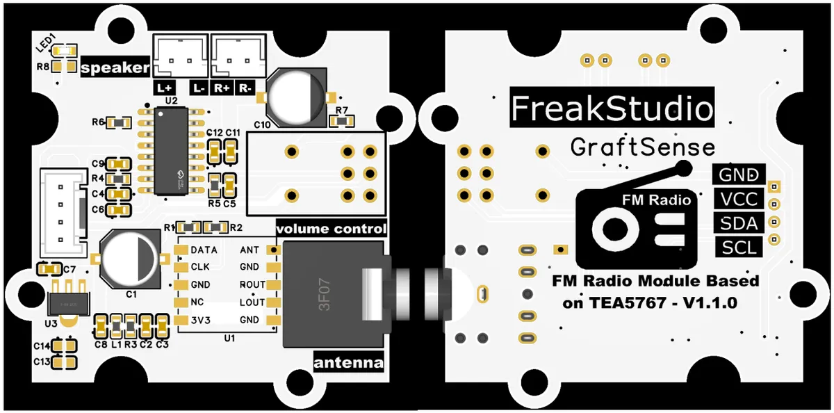
This module provides an I²C communication interface: it supports a maximum communication rate of 400kHz, with a fixed slave address of 110 0000b, is compatible with 3.3V level MCUs, and enables digital frequency adjustment, automatic channel searching, mute control and stereo mode switching via standard I²C commands;Paired with the TEA5767 radio chip and PAM8403 power amplifier circuit, it can drive a 4Ω loudspeaker with a single 5V power supply, covering the full 76~108MHz band FM broadcasts. It is suitable for scenarios including portable radios, smart speakers and campus broadcasting, and provides the system with stable and reliable digital FM radio control capability.
Here, we have equipped the module with a number of interfaces:
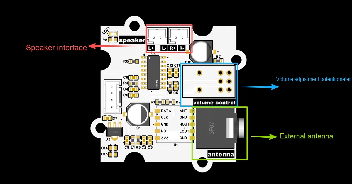
Including:
- Speaker Interface: Outputs left and right channel audio to directly drive 4Ω speakers for sound production.
- Volume adjustment potentiometer interface: Connect an external potentiometer to manually adjust the output volume of the radio.
- External Antenna Interface: 3.5mm standard port, used to connect the FM telescopic antenna to enhance the signal reception capability for the full 76~108MHz broadcast band.
- I²C communication interface: 3.3V level I²C bus, used to connect to the main control MCU to realize digital control functions such as digital channel tuning, automatic channel searching, mute, and stereo switching.
3.3 Application Experiment
Here, we use the GraftPort-RP2040 development board for testing, and the FM radio module based on the TEA5767 module uses the I2C interface to communicate with the main controller.
Here, we first use the HY2.0-4P cable to connect the module to the GraftPort-RP2040 development board's I2C0 interface:
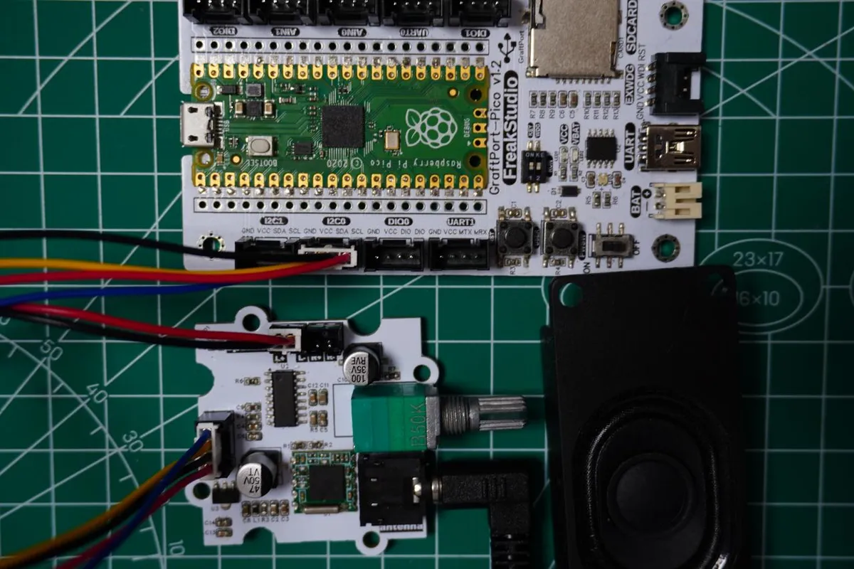
The module connections are shown in the following table:
Development Board Pins | Module Pins | Description |
Pin 4 |
|
|
Pin 5 |
|
|
At the same time, connect the 3.5mm FM telescopic antenna to the antenna interface, and connect the external speaker to the speaker interface:
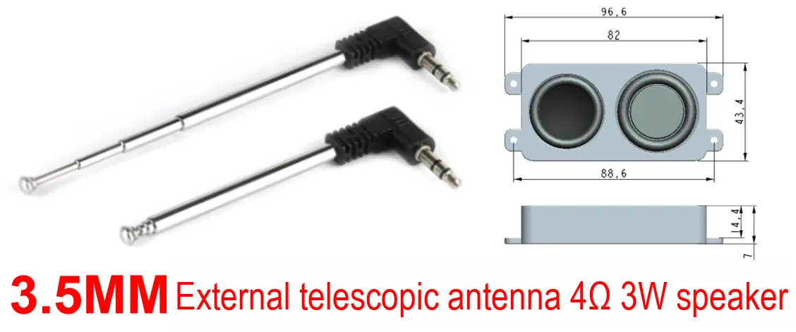
Here, we need to search for the relevant driver packages on uPyPI: https://upypi.net/zh/
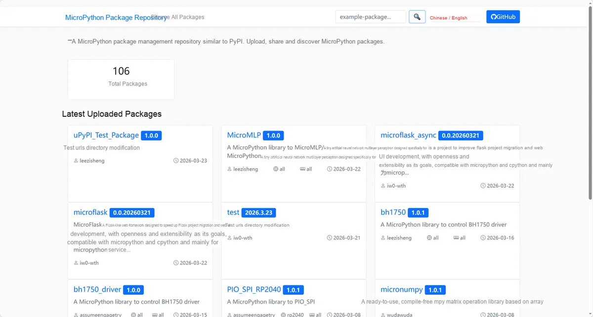
Enter tea5767_driver to search, and the following will be displayed:

Click to copy the local installation command:
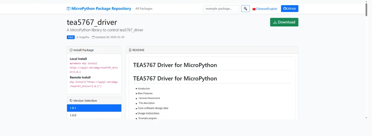
Import the module driver library code via the mip tool. Below are the usage commands for the mpremote tool:
mpremote mip install https://upypi.net/pkgs/tea5767_driver/1.0.0Import the FM radio module based on the TEA5767 module - MicroPython driver code, then copy the following main.py code into our project:
# Python env   : MicroPython v1.23.0
# -*- coding: utf-8 -*-
# @Time    : 2025/9/9
# @Author  : hogeiha
# @File    : tea5767_search_max_signal_simple.py
# @Description : Search for the highest-signal frequency based on the existing Radio class (no new classes)

# ======================================== Import Modules =========================================

import time
from machine import I2C, Pin

# Import the existing Radio class
from tea5767 import Radio

# ======================================== Global Variables ============================================

# Pico I2C SCL pin
I2C_SCL = 5
# Pico I2C SDA pin
I2C_SDA = 4
# Tea5767 default I2C address
RADIO_ADDR = 0x60
# Search band: US (87.5-108.0) / JP (76.0-91.0)
SEARCH_BAND = "US"
# FM frequency step (fixed at 0.1 MHz)
STEP = 0.1
# 2. Define the band range
freq_min, freq_max = Radio.FREQ_RANGE_US if SEARCH_BAND == "US" else Radio.FREQ_RANGE_JP
current_freq = freq_min
max_signal_freq = current_freq
max_signal_level = 0

# ======================================== Functions ============================================

# ======================================== Custom Classes ============================================

# ======================================== Initialization ==========================================

# Additional initialization configuration required by the project
time.sleep(3)
print("FreakStudio: Tea5767 max signal search start")

# 1. Initialize the I2C and Radio instances
i2c = I2C(0, scl=Pin(I2C_SCL), sda=Pin(I2C_SDA), freq=400000)
devices_list: list[int] = i2c.scan()

print("START I2C SCANNER")

# If the devices list is empty, no device is connected to the I2C bus
if len(devices_list) == 0:
    # If not empty, print the slave device addresses
    print("No i2c device !")
else:
    # Iterate over the slave device address list
    print("i2c devices found:", len(devices_list))
for device in devices_list:
    # Check whether the device address is the RADIO address
    if device == 0x60:
        # The device found is the RADIO address
        print("I2c hexadecimal address:", hex(device))
        RADIO_ADDR = device

if RADIO_ADDR not in i2c.scan():
    print(f"Error: Tea5767 module not detected (I2C address {hex(RADIO_ADDR)})")
else:
    # Initialize the Radio (turn off interference detection to ensure accurate signal readings)
    radio = Radio(
        i2c=i2c, addr=RADIO_ADDR, freq=87.5 if SEARCH_BAND == "US" else 76.0, band=SEARCH_BAND, soft_mute=False, noise_cancel=False, high_cut=False
    )
    print(f"Starting {SEARCH_BAND} band scanning...")

# ========================================  Main Program  ===========================================

# 3. Scan signal strength frequency by frequency
while current_freq <= freq_max:
    # Set the current frequency and wait for it to stabilize
    radio.set_frequency(current_freq)
    time.sleep_ms(20)
    # Read the latest status
    radio.read()

    # Update the highest signal record
    if radio.signal_adc_level > max_signal_level:
        max_signal_level = radio.signal_adc_level
        max_signal_freq = current_freq

    # Frequency step (keep 1 decimal place to avoid floating-point error)
    current_freq = round(current_freq + STEP, 1)

# 4. Switch to the highest signal frequency and output the result
radio.set_frequency(max_signal_freq)
time.sleep_ms(50)
radio.read()

# Restore optimized configuration (soft mute / noise reduction)
radio.soft_mute_mode = True
radio.stereo_noise_cancelling_mode = True
radio.update()

# Print the final result
print("=" * 40)
print("Scanning completed!")
print(f"Max signal frequency: {max_signal_freq} MHz")
print(f"Signal strength level: {max_signal_level} (0-15, higher is stronger)")
print(f"Stereo mode: {'Yes' if radio.is_stereo else 'No'}")
print("=" * 40)

while True:
    pass
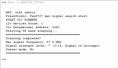
In the code above, we automatically scan all FM frequencies within the specified frequency band (US / Japan), detect and compare the signal strength point by point, lock the frequency with the strongest signal for playback, and finally print out the optimal frequency, signal strength and stereo status to complete the fully automatic station search and optimization function.
Burn the code, open the terminal, and the output is as follows:
After implementing the above functions, the radio can normally output the sound of the current optimal signal station as follows:
TEA5767_Module_Demo.m4a 102 KB
IV. Drivers
tea5767_driver-1.0.1.zip 13 KB
5. BOM & Recommended Alternative Parts
None.
VI. Revision History
Document Version | Date Modified | Modifier | Modify Content |
v1.0 | 2026-03-30 | Ling Gaoxing | Initialize the document |
v1.0.1 | 2026-04-05 | Li Zisheng | The cover photo has not been taken, the production files have not been exported yet, and all other items have been sorted out. |
v1.0.2 | 2026-04-21 | Li Zisheng | The production documents have not been exported yet, and all the rest have been sorted out. |
v1.1 | 2026-04-23 | Xin Ruili | Create an open version of the document based on the internal document version v1.0.2. |
7. Relevant Materials
7.1 Chip Datasheet
TEA5767.pdf 200 KB
7.2 Unique Icons for PCB Silk Screen