Contents
- I. Module Introduction
- II. Introduction to Main Chips
- 2.1 Chip Overview
- 2.2 Pin Definition
- 2.3 Functional Block Diagram
- 2.4 Performance Parameters
- 2.5 Reference Circuit
- 2.6 Chip Configuration
- 2.7 Communication Interfaces and Related Protocols
- 2.8 PCB Routing Precautions
- III. Circuit Engineering
- 3.1 Circuit Source Engineering
- 3.2 Module Usage Instructions
- 3.3 Application Experiment
- IV. Drivers
- 5. BOM & Recommended Alternative Parts
- VI. Revision History
- 7. Relevant Materials
- 7.1 Chip Datasheet
- 7.2 Unique Icons for PCB Silk Screen
I. Module Introduction
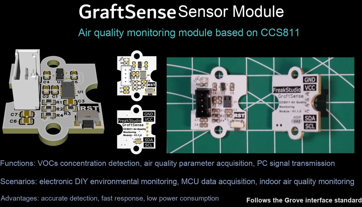
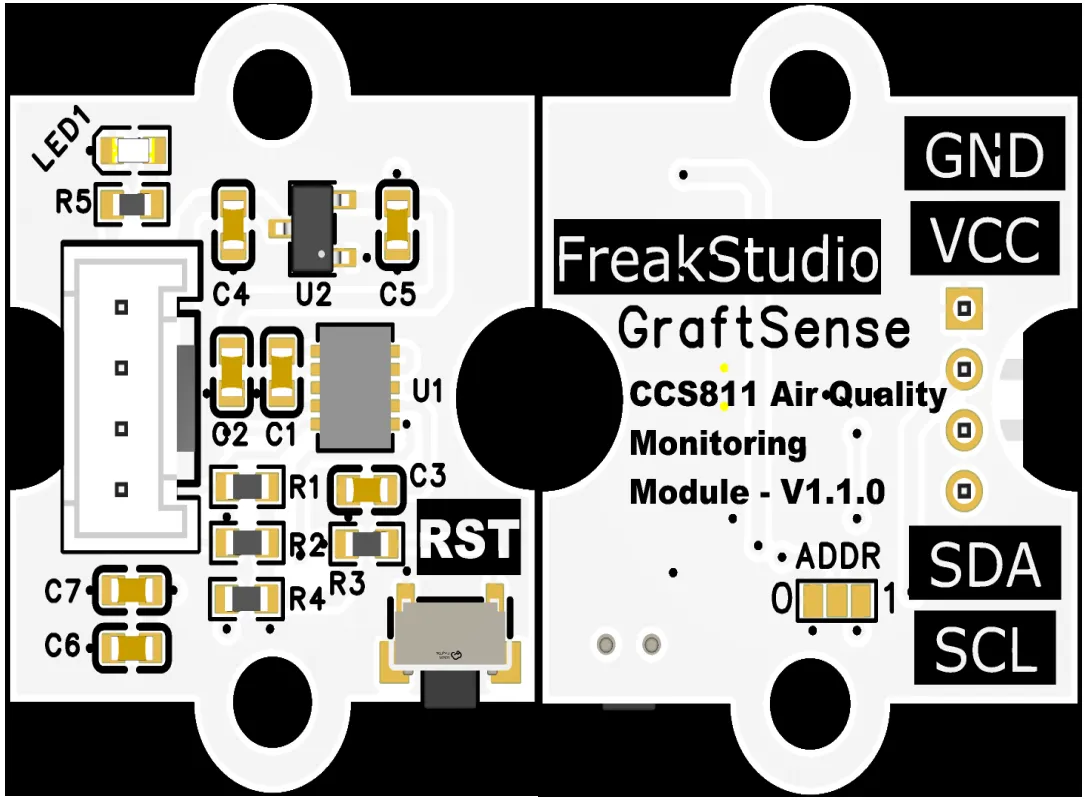
Air quality monitoring module based on CCS811, which adopts the CCS811B-JOPD500 chip solution, is an ultra-low power indoor air quality digital gas sensor integrated with metal oxide gas sensing elements, ADC and on-chip MCU, and directly outputs the concentration data of I²C interface: eCO₂(400ppm~8192ppm) and TVOC (0~1187ppb);The module integrates LDO voltage regulation, power filtering and I²C pull-up circuits. The device address can be configured via the ADDR pin as either 0x5A or 0x5B. Equipped with a power indicator and a reset pin, it supports multiple measurement periods including 1s, 10s, 60s and 250ms, and is compatible with 3.3V level MCU, making it suitable for indoor environmental monitoring, portable air quality detection and low-power IoT scenarios.
II. Introduction to Main Chips
CCS811 is an ultra-low power digital gas sensor that integrates a MOX gas-sensitive element and an on-chip MCU. It outputs I²C interface eCO₂(400ppm~8192ppm) and TVOC (0~1187ppb) data, supports multiple measurement periods, and is suitable for indoor air quality monitoring.
2.1 Chip Overview
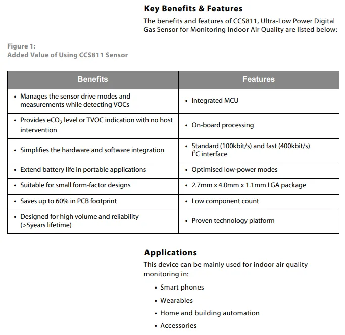
CCS811 sensor's core advantages lie in simplifying software and hardware integration, outputting eCO ₂/ TVOC data without host intervention, extending the battery life of portable devices and reducing the PCB footprint; its features cover an integrated MCU, on-board processing, 100kbit/s/400kbit/s I²C interface, optimized low-power mode and a compact 2.7mm×4.0mm×1.1mm LGA package, along with a small number of components and a mature technical platform;It is mainly used in indoor air quality monitoring scenarios such as smartphones, wearable devices, home and building automation, and accessories.
2.2 Pin Definition
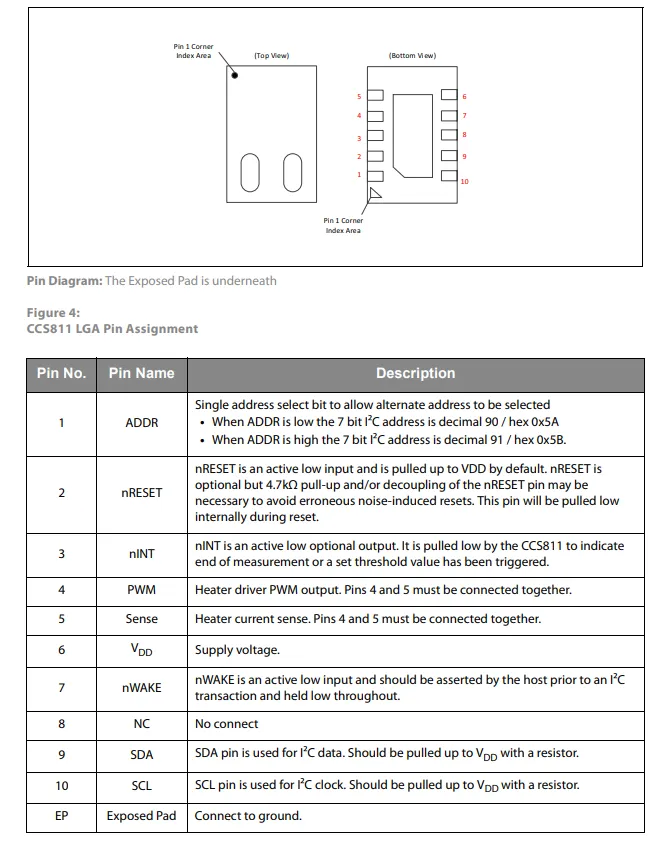
CCS811 chip specifies the number, name and detailed function description of 10 pins (including functional pins such as ADDR, nRESET, SDA / SCL, etc.), such as I²C address, high and low level characteristics, and communication rules. It also presents the pin layout of the LGA package and the grounding requirements of the exposed pad (EP), and clearly marks the electrical characteristics and application specifications of each pin.
2.3 Functional Block Diagram
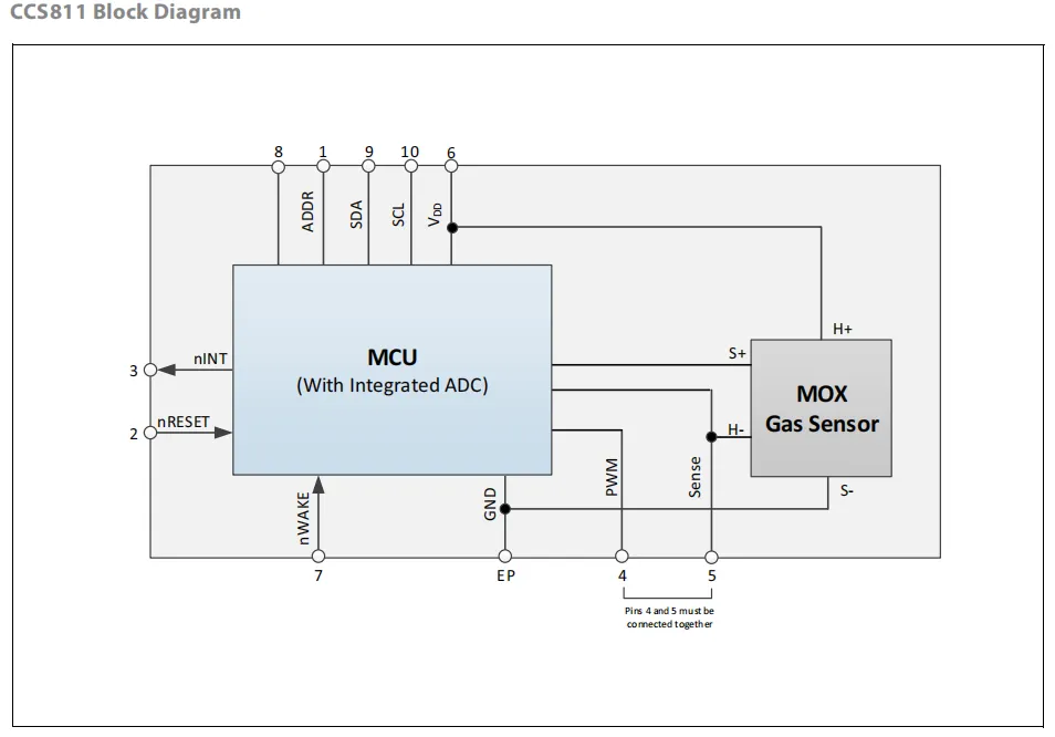
The chip integrates a built-in ADC, MCU, MOX gas sensor and peripheral circuits, and communicates with external devices via the I²C interface (SCL / SDA). Its core principle is as follows: the MCU uses the internal ADC to collect signals from the MOX sensor, controls the start and stop of the circuit through nRESET reset and nWAKE wake-up, and supports switching between standard mode and low-power mode. With GND as the electrical reference, the chip realizes coordinated management of signals and power supply.
2.4 Performance Parameters
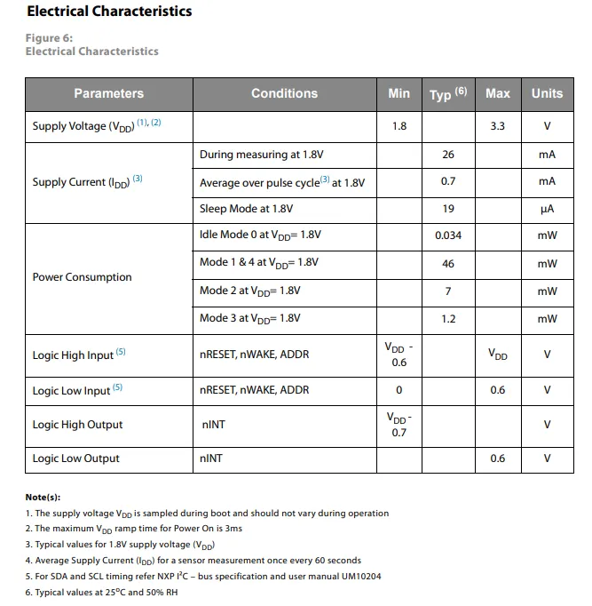
CCS811 has a supply voltage range of 1.8V to 3.3V. When powered at 1.8V, its typical current in measurement mode is 26mA, the average current over pulse cycles is 0.7mA, and the current in sleep mode is only 19μA; its power consumption ranges from 0.034mW (idle mode 0) to 46mW (mode 1 & 4) depending on the operating mode.In terms of digital levels, the input high level ranges from VDD -0.6 V to VDD, and the input low level ranges from 0 to 0.6 V; the high level output by nINT ranges from VDD -0.7 V to VDD, and the low level is ≤ 0.6 V. Notes such as power-on sequence and typical test conditions are also specified.
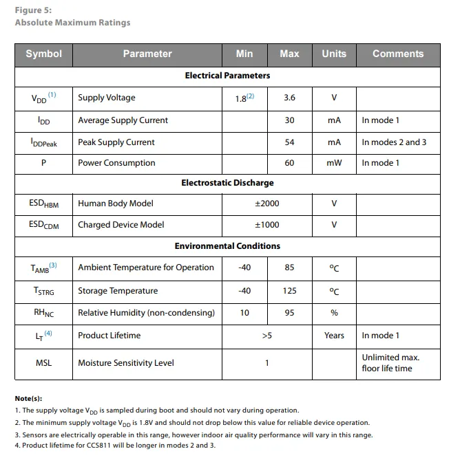
The absolute maximum rated electrical parameters of the CCS811 are specified as follows: supply voltage range 1.8V~3.6V, average supply current 30mA in Mode 1, peak current 54mA (Mode 2/3), power consumption 60mW;ESD protection meets HBM ±2000V, CDM ±1000V;In terms of environmental parameters, the operating temperature ranges from -40℃ to 85℃, the storage temperature ranges from -40℃ to 125℃, the relative humidity is 10%~95%(non-condensing), the product lifespan is more than 5 years (Mode 1), and the moisture sensitivity level is Grade 1. Meanwhile, usage precautions such as power supply voltage sampling and minimum power supply voltage constraints are also specified in the remarks.
2.5 Reference Circuit
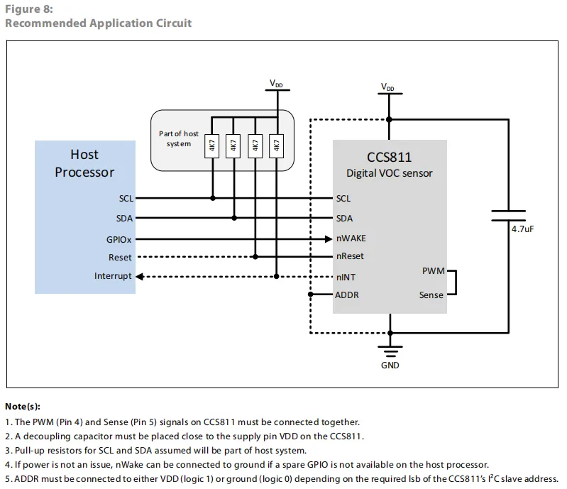
CCS811 host processor through the I ² C interface ( SCL / SDA , need 4.7kΩ pull-up resistor) and CCS811 communication, while through the GPIO control nWAKE pin, reset pin nReset , and receive the interrupt signal nINT ;CCS811 's PWM and Sense pins must be shorted. VDD pin requires a 4.7μF decoupling capacitor placed nearby. ADDR pin is connected to VDD or GND to configure the I²C address. nWAKE can be directly grounded when power supply is sufficient to simplify the design.
2.6 Chip Configuration
None.
2.7 Communication Interfaces and Related Protocols
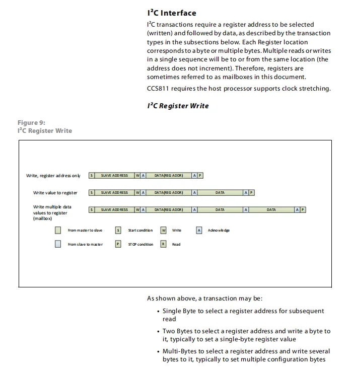
CCS811 I²C requires that the register address be selected first (for write operations) before data transmission, and supports three types of write transactions — writing only the register address, writing a single byte of data to the register, and writing multiple bytes of data to the same register (mailbox mode), with no automatic address increment; the chip requires the host to support clock stretching, and the Sequence Diagram clearly marks the transmission process of the start condition, slave address, write bit, register address, data, acknowledge and stop condition.
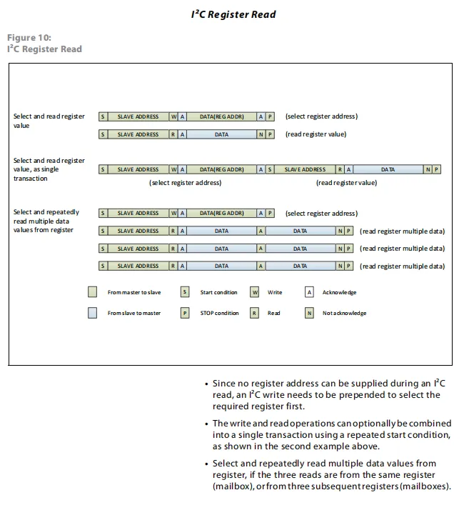
CCS811 during I²C read operations, since the I²C read operation cannot directly provide the register address, it is necessary to first send a write transaction to select the target register, then read data through a read transaction; it supports modes such as single-byte read, read-write completed in a single transaction (with repeated start condition), and continuous multi-byte read (for the same register buffer or consecutive registers), and the Sequence Diagram clearly defines the signal processes including Start (S), Write (W), Read (R), Acknowledge (A), Not Acknowledge (N), Stop (P) between master-slave interactions.
2.8 PCB Routing Precautions
None.
III. Circuit Engineering
3.1 Circuit Source Engineering
To obtain the circuit source project, please follow the official account [Freak Embedded].
3.2 Module Usage Instructions
The schematic diagram of this module is shown below:
SCH_Air Quality Monitoring Module Based on CCS811-V1.1.0_2026-03-30.pdf 2.1 MB
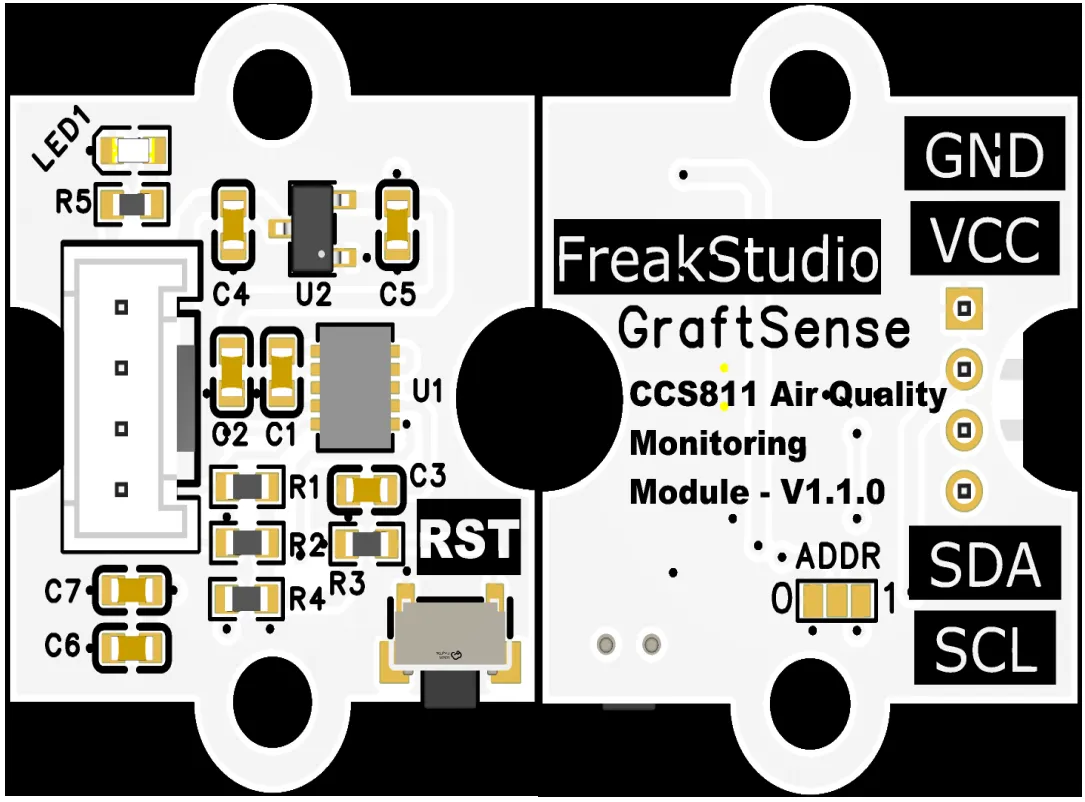
This module provides an I²C communication interface: it supports standard (100 kbit/s) and fast (400 kbit/s) I²C communication rates, the device address can be flexibly configured to ADDR via the pin as 0x5A or 0x5B, and it is compatible with 3.3V level MCU;The module integrates LDO voltage regulation, power filtering and I²C pull-up circuits, is equipped with a power indicator and a reset pin, and can directly output eCO₂(400ppm~8192ppm) and TVOC (0~1187ppb) concentration data. It supports multiple measurement cycles of 1 second / 10 seconds / 60 seconds / 250 milliseconds, is suitable for indoor environment monitoring, portable air quality detection and low-power IoT scenarios, and provides reliable air quality Data Acquisition and interaction capabilities for the system.
At the same time, the module is equipped with an on-board RST reset button, which can be pressed when a chip read/write failure occurs.
3.3 Application Experiment
Here, we use the GraftPort-RP2040 development board for testing, and the CCS811-based air quality monitoring module uses the I2C interface to communicate with the main controller.
Here, we first use the HY2.0-4P cable to connect the module to the GraftPort-RP2040 development board's I2C0 interface:
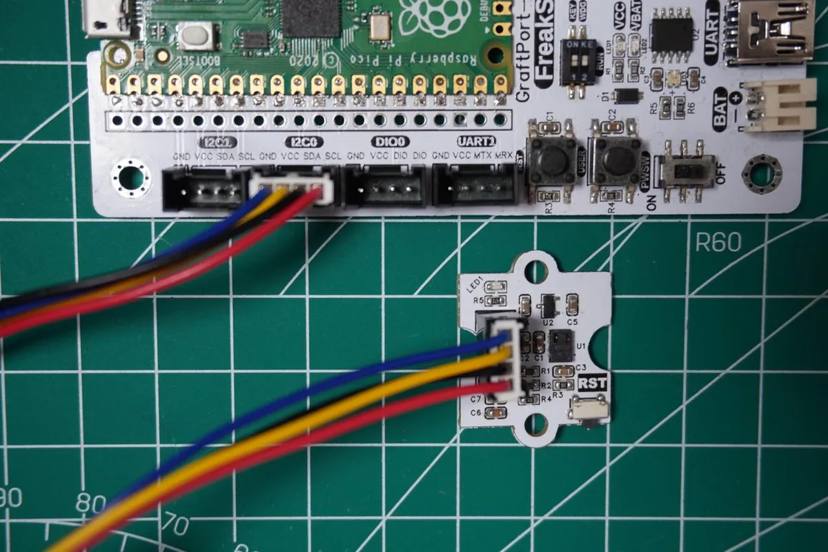
The module connections are shown in the following table:
Development Board Pins | Module Pins | Description |
Pin 4 |
|
|
Pin 5 |
|
|
Here, we need to search for the relevant driver packages on uPyPI: https://upypi.net/zh/
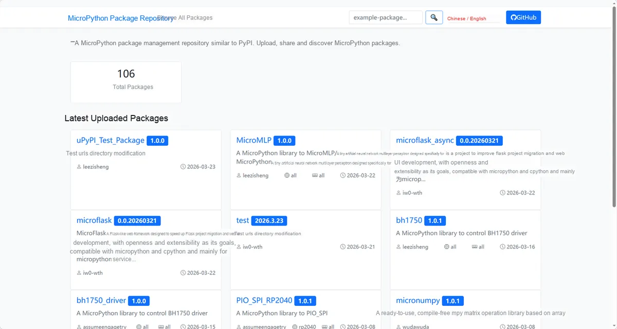
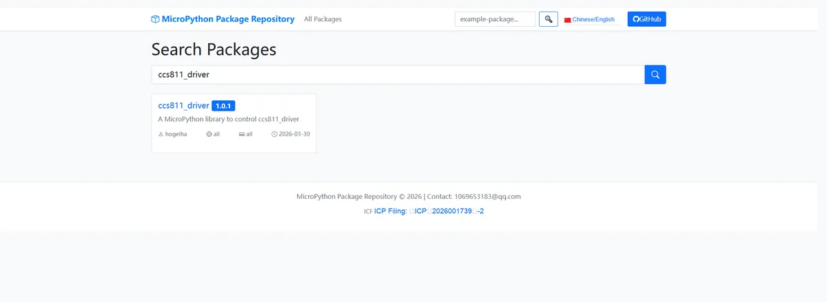
Enter ccs811_driver to search, and the following will be displayed:
Click to copy the local installation command:
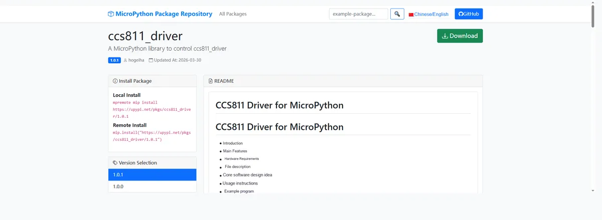
Import the module driver library code via the mip tool. Below are the usage commands for the mpremote tool:
mpremote mip install https://upypi.net/pkgs/ccs811_driver/1.0.0Import the CCS811-based air quality monitoring module - MicroPython driver code, then copy the following main.py code into our project:
# Python env   : MicroPython v1.23.0
# -*- coding: utf-8 -*-
# @Time    : 2026/3/12 4:12 PM
# @Author  : hogeiha
# @File    : main.py
# @Description : CCS811 sensor test: read eCO2 and TVOC data, configure drive mode, software reset the sensor

# ======================================== Import Modules =========================================

from machine import I2C, Pin, SoftI2C
import time
from ccs811 import CCS811

# ======================================== Global Variables ============================================

# Automatically identify the sensor address, define a global target address list (supports multiple addresses; use [] even for a single one)
TARGET_CCS811_ADDRS = [0x5A,0x5B]
I2C_SDA_PIN = 4
I2C_SCL_PIN = 5
I2C_FREQ = 100000

# ======================================== Functions ============================================

# ======================================== Custom Classes ============================================

# ======================================== Initialization configuration ===========================================

time.sleep(3)
print("FreakStudio: CCS811 sensor test - read eCO2 and TVOC data, configure drive mode, software reset sensor")

# I2C initialization (compatible with I2C/SoftI2C)
i2c_bus = I2C(0, scl=Pin(I2C_SCL_PIN), sda=Pin(I2C_SDA_PIN), freq=I2C_FREQ)

# Start scanning for devices on the I2C bus
devices_list: list[int] = i2c_bus.scan()
print("START I2C SCANNER")

# Check the I2C device scan result
if len(devices_list) == 0:
    print("No i2c device !")
    raise SystemExit("I2C scan found no devices, program exited")
else:
    print("i2c devices found:", len(devices_list))

# Iterate over the address list to initialize the target sensor
sensor = None  # Placeholder for the sensor object initialization
for device in devices_list:
    if device in TARGET_CCS811_ADDRS:
        print("I2c hexadecimal address:", hex(device))
        try:
            # Automatically identify and initialize the corresponding sensor
            sensor = CCS811(i2c=i2c_bus,addr = device)
            print("Sensor initialization successful")
            break
        except Exception as e:
            print(f"Sensor Initialization failed: {e}")
            continue
else:
    # Target device not found, raise an exception
    raise Exception("No target sensor device found in I2C bus")

# ========================================  Main Program  ============================================

try:
    # Initialize CCS811 sensor
    sensor.setup()
    time.sleep(2)  # Wait for stabilization after initialization

    # Check whether APP is valid
    app_valid = sensor.app_valid()
    print(f"\nAPP validity: {app_valid}")

    # Check whether the sensor has errors
    has_error = sensor.check_for_error()
    print(f"Sensor error status: {has_error}")

    # Get sensor baseline value
    baseline = sensor.get_base_line()
    print(f"Sensor baseline value: 0x{baseline:04X}")

    # Change drive mode to once per second
    print("\nSet drive mode to 1 second per reading...")
    sensor.set_drive_mode(1)
    time.sleep(1)

    # Read eCO2 and TVOC data in a loop (5 reads)
    print("\nStart reading sensor data (5 times):")
    for i in range(5):
        co2 = sensor.read_eCO2()
        time.sleep(2)  # Wait according to drive mode
        tvoc = sensor.read_tVOC()
        print(f"Reading {i+1} - eCO2: {co2} ppm, TVOC: {tvoc} ppb")
        time.sleep(2)  # Wait according to drive mode

    # Perform sensor software reset
    print("\nPerform sensor software reset...")
    sensor.reset()
    time.sleep(2)

    # Re-initialize after reset and read data once
    print("\nRe-initialize after reset...")
    sensor.setup()
    time.sleep(2)
    co2 = sensor.read_eCO2()
    tvoc = sensor.read_tVOC()
    print(f"Reading after reset - eCO2: {co2} ppm, TVOC: {tvoc} ppb")

except ValueError as e:
    print(f"Runtime error: {e}")
except Exception as e:
    print(f"Unknown error: {e}")
Burn the code, open the terminal, and the output is as follows:
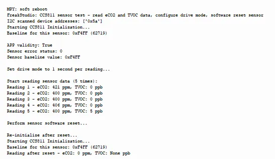
We can see that it can normally read eCO2 and TVOC data and perform a software reset.
IV. Drivers
ccs811_driver-1.0.1.zip 11 KB
5. BOM & Recommended Alternative Parts
None.
VI. Revision History
Document Version | Date Modified | Modifier | Modify Content |
v1.0 | 2026-03-30 | Ling Gaoxing | Initialize the document |
v1.0.1 | 2026-04-05 | Li Zisheng | The cover photo has not been taken, the production files have not been exported yet, and all other items have been sorted out. |
v1.0.2 | 2026-04-21 | Li Zisheng | The production documents have not been exported yet, and all the rest have been sorted out. |
v1.1 | 2026-04-23 | Xin Ruili | Create an open version of the document based on the internal document version v1.0.2. |
7. Relevant Materials
7.1 Chip Datasheet
CCS811B-JOPD500.pdf 499 KB
7.2 Unique Icons for PCB Silk Screen