Contents
- I. Module Introduction
- II. Introduction to Main Chips
- 2.1 Chip Overview
- 2.2 Pin Definition
- 2.3 Functional Block Diagram
- 2.4 Performance Parameters
- 2.5 Reference Circuit
- 2.6 Chip Configuration
- 2.7 Communication Interfaces and Related Protocols
- 2.8 PCB Routing
- III. Circuit Engineering
- 3.1 Circuit Source Engineering
- 3.2 Module Usage Instructions
- 3.3 Application Experiment
- IV. Drivers
- 5. BOM & Recommended Alternative Parts
- 6. Revision History
- VII. Relevant Materials
- 7.1 Chip Datasheet
- 7.2 Unique Icons for PCB Silk Screen
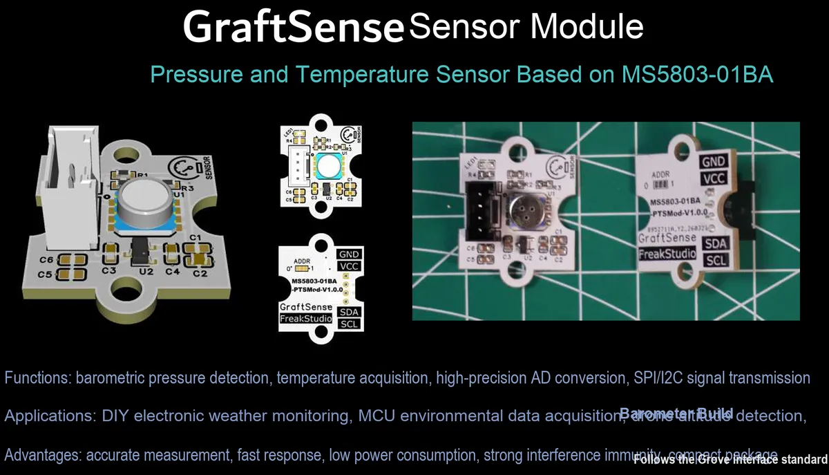
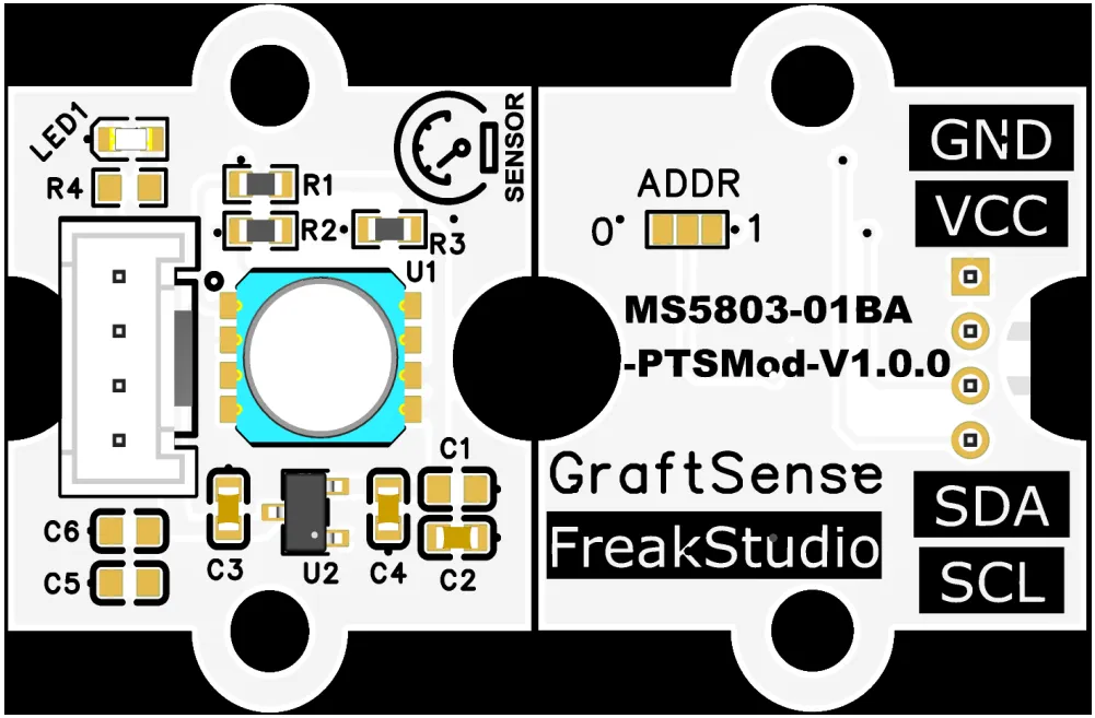
I. Module Introduction
Pressure and Temperature Sensor Module Based on MS5803-01BA, adopting the MS5803-01BA chip solution, is a high-precision integrated pressure and temperature sensor with a built-in 24-bit ADC, supporting configurable OSR oversampling rates from 256 to 4096, a pressure measurement range of 10 to 1300 mbar, and a resolution of up to 0.2 mbar;The module integrates LDO voltage regulation, power filtering and I²C pull-up circuits. The ADDR pin allows selection of the I²C address as either 0x77 or 0x76. Equipped with a power indicator, it is compatible with 3.3V level MCUs, and suitable for weather monitoring, altimeters, portable pressure detection, and low-power IoT scenarios.
II. Introduction to Main Chips
MS5803-01BA is a high-precision 24-bit integrated pressure and temperature sensor with I²C interface output, a pressure range of 10~1300 mbar, a resolution of 0.2 mbar, and support for programmable OSR oversampling, which is suitable for air pressure measurement and altitude detection scenarios.
2.1 Chip Overview
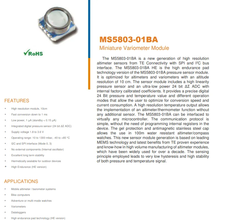
MS5803-01BA is a high-precision barometric altimeter module launched by TE Connectivity, which adopts I²C / SPI interface, has a built-in 24-bit ΔΣ ADC, supports pressure measurement of 10~1300 mbar and temperature measurement of -40~+ 85℃, with an altitude resolution up to 10 cm. It features low power consumption (standby current < 0.15 μA), fast conversion and high long-term stability, requires no external components, and can directly output factory-calibrated pressure/temperature data, making it suitable for scenarios such as altimeters, barometers and wearable devices.
2.2 Pin Definition
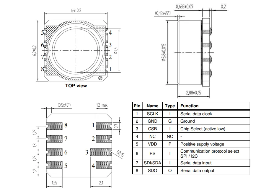
MS5803-01BA adopts an 8-pin LGA package, and provides precise mechanical dimensions for the top view, side view and bottom view (e. g. 6.4±0.2mm×6.2±0.2mm); the pin functions are clearly defined, including I²C / SPI communication interfaces (SCLK, SDI / SDA, SDO), chip select (CSB), protocol select (PS), power supply (VDD) and ground (GND), etc. It supports switching the Communication Protocol via the PS pin, where pin 4 is not connected (NC).
2.3 Functional Block Diagram
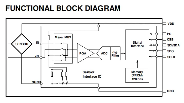
The sensor interface is an IC that integrates sensor inputs, a measurement multiplexer (Meas. MUX), a programmable gain amplifier (PGA), an analog-to-digital converter (ADC), a digital filter, a digital interface, and 128-bit programmable PROM memory;After external signals are input via the sensor, they are routed through MUX switching to be amplified by PGA, then converted into digital signals by ADC and processed with digital filtering, before being output via a digital interface; meanwhile, the data can be written into PROM for storage, the device is powered by VDD and grounded via GND, and supports configuring Communication Protocol and enabling control through pins including PS, CSB and others.
2.4 Performance Parameters
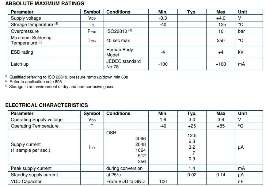
MS5803-01BA has several parameters requiring attention in terms of its absolute maximum ratings: power supply voltage range - 0.3V to 4.0V, storage temperature - 40℃ to 125℃, overvoltage withstand 10bar, ESD protection (HBM) ±4kV;Several parameters requiring attention in terms of electrical characteristics are as follows: operating voltage 1.8V~3.6V, operating temperature -40~85°C, the supply current decreases as OSR decreases (typical value is 0.9μA when OSR = 256), typical standby current 0.02μA, maximum standby current 0.14μA, peak conversion current 1.4mA; meanwhile, a 100nF capacitor is required to be configured between VDD and GND.
2.5 Reference Circuit
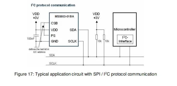
The MS5803-01BA chip is powered by a 3V supply. A 100nF decoupling capacitor is placed close to the VDD pin. The CSB pin is connected to VDD to select the I²C communication mode. The logic level on the PS pin determines the least significant bit of the I²C address. The SDA and SCL pins are pulled up to VDD via 10kΩ resistors, and connected to the I²C interface of the microcontroller to enable digital communication of pressure and temperature data.
2.6 Chip Configuration
None.
2.7 Communication Interfaces and Related Protocols
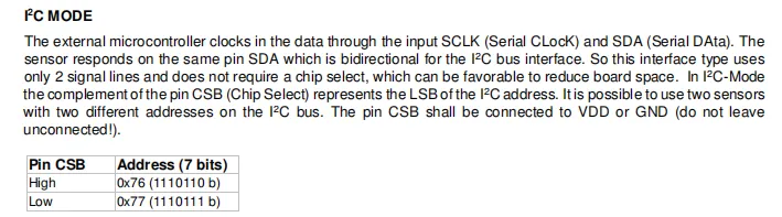
MS5803-01BA I²C communication only requires two signal lines: SCLK (clock) and bidirectional SDA (data), with no chip select required, thus saving PCB space; the level of the CSB pin determines the least significant bit of the 7-bit I²C address: when connected to high level, the address is 0x76, and when connected to low level, it is 0x77, which supports mounting two sensors on the same bus. Additionally, the CSB pin must be connected to VDD or GND and must not be left floating.
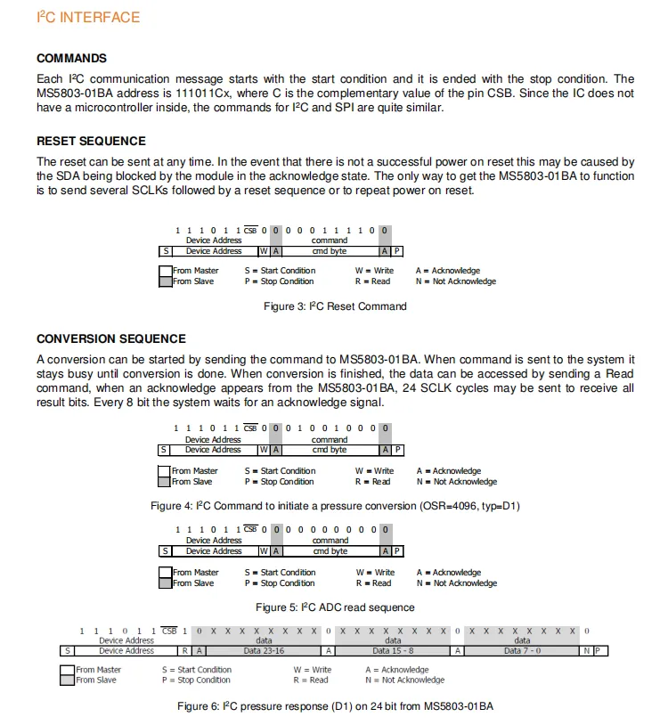
MS5803-01BA performs I²C communication bounded by start/stop conditions, with the device address being 111011Cx (C is the inverse of the CSB pin level); it supports reset commands (which can be sent at any time to release SDA blocking), conversion commands (to initiate pressure/temperature measurement, during which the chip remains busy until the conversion is complete), and 24-bit data read commands. The Sequence Diagram clearly illustrates the complete interaction flow of reset, conversion initiation, and ADC result reading, covering signals such as start, write/read, acknowledge, and stop between the master and slave devices.
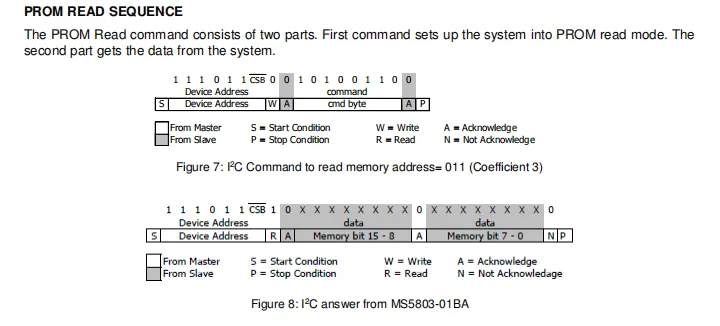
MS5803-01BA PROM read operation consists of two steps: first, send a write command to enter read mode and specify the target memory address, then send a read command to obtain 16-bit data (upper 8 bits + lower 8 bits); the device address is 111011, and the Sequence Diagram clearly demonstrates the complete interaction process between the master and slave devices, including Start (S), Write (W)/Read (R), Acknowledge (A)/Not Acknowledge (N), and Stop (P), which is used for reading factory calibration coefficients.
2.8 PCB Routing
None.
III. Circuit Engineering
3.1 Circuit Source Engineering
To obtain the circuit source project, please follow the official account [Freak Embedded].
3.2 Module Usage Instructions
The schematic diagram of this module is shown below:
SCH_Pressure and Temperature Sensor Based on MS5803-01BA-V1.0.0_2026-03-30.pdf 2.3 MB
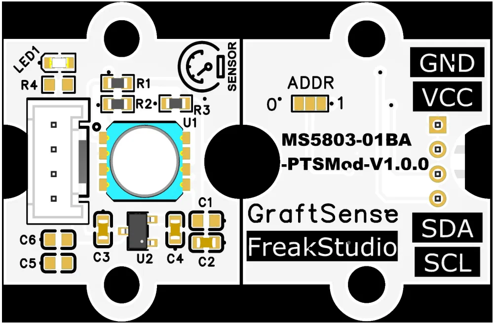
This module provides an I²C communication interface: it supports standard (100 kbit/s) and fast (400 kbit/s) I²C communication rates. The device address can be flexibly configured to ADDR via the pin as either 0x77 or 0x76, and it is compatible with 3.3V level MCUs;The module integrates LDO voltage regulation, power filtering and I²C pull-up circuits, is equipped with a power indicator, can output high-precision pressure (10~1300 mbar, resolution 0.2 mbar) and temperature data, supports configurable OSR (oversampling ratio) from 256 to 4096, is suitable for meteorological monitoring, altimeters, portable pressure detection and low-power IoT scenarios, and provides reliable environmental parameter acquisition and interaction capabilities for the system.
3.3 Application Experiment
Here, we use the GraftPort-RP2040 development board for testing, and the MS5803-01BA-based pressure and temperature sensor uses the I2C interface to communicate with the main controller.
Here, we first use the HY2.0-4P connection cable to connect the module to the GraftPort-RP2040 development board's I2C0 interface:
The module connections are shown in the following table:
Development Board Pins | Module Pins | Description |
Pin 4 |
|
|
Pin 5 |
|
|
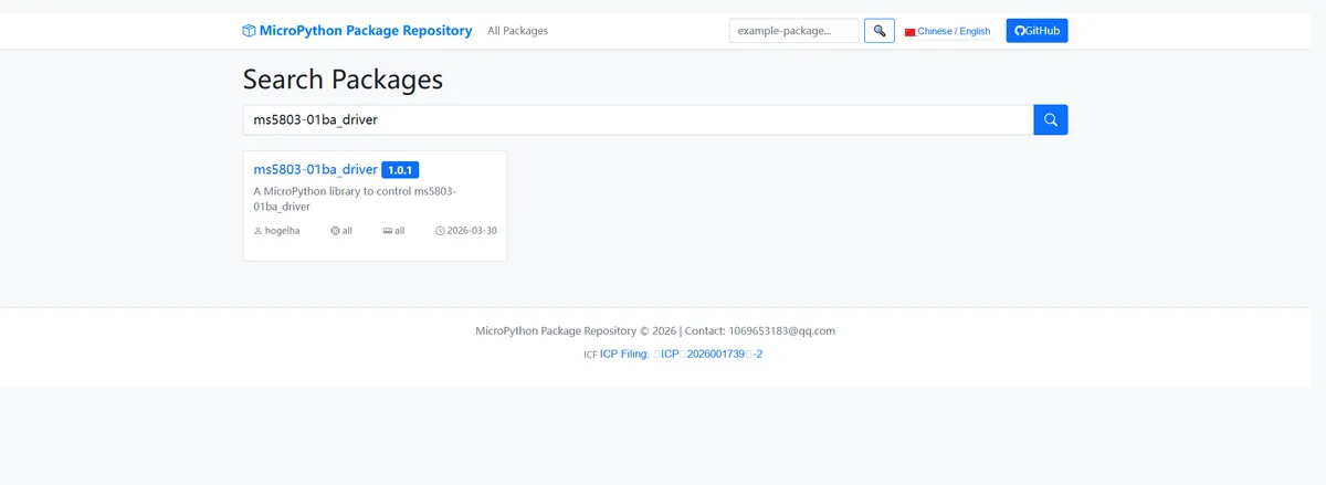
Here, we need to search for the relevant driver packages on uPyPI: https://upypi.net/zh/
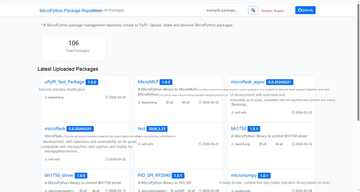
Enter ms5803-01ba_driver to search, and the following will be displayed:
Click to copy the local installation command:
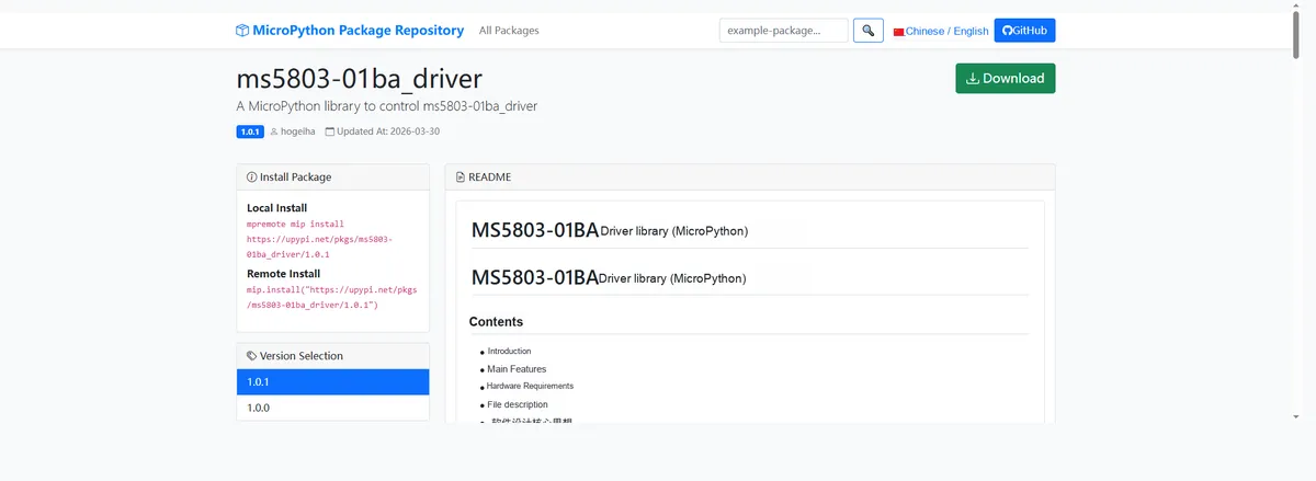
Import the module driver library code via the mip tool. Below are the usage commands for the mpremote tool:
mpremote mip install https://upypi.net/pkgs/ms5803-01ba_driver/1.0.0Import the pressure and temperature sensor based on MS5803-01BA - MicroPython driver code, then copy the following main.py code into our project:
# Python env   : MicroPython v1.23.0
# -*- coding: utf-8 -*-
# @Time    : 2026/3/14 11:00 AM
# @Author  : minyiky
# @File    : main.py
# @Description : MS5803 temperature and pressure sensor test: initialize the sensor, read raw data, switch units to read temperature and pressure data

# ======================================== Import Modules =========================================

# Import the Pin and I2C modules for hardware communication
from machine import Pin, I2C

# Import the time module for delays
import time

# Import the MS5803 sensor driver class
from ms5803 import MS5803  # Import the original driver

# ======================================== Global Variables ============================================

# Define the I2C SCL pin number (for Raspberry Pi Pico)
I2C_SCL_PIN = 5
# Define the I2C SDA pin number (for Raspberry Pi Pico)
I2C_SDA_PIN = 4
# Define the I2C communication frequency
I2C_FREQ = 400000
# List of I2C addresses supported by the MS5803 sensor
TARGET_SENSOR_ADDRS = [0x76, 0x77]
# Declare the MS5803 sensor object variable
ms_sensor = None

# ======================================== Functions ============================================

# ======================================== Custom Classes ============================================

# ======================================== Initialization configuration ===========================================

time.sleep(3)
print("FreakStudio: MS5803 Temperature and Pressure Sensor Test")

# Initialize the I2C bus with the specified pins and frequency
i2c_bus = I2C(0, scl=Pin(I2C_SCL_PIN), sda=Pin(I2C_SDA_PIN), freq=I2C_FREQ)
# Scan all device addresses on the I2C bus
devices_list: list[int] = i2c_bus.scan()
# Print the I2C scan start message
print("START I2C SCANNER")
# Check whether any I2C devices were found
if len(devices_list) == 0:
    # Print the no I2C device message
    print("No i2c device !")
    # Raise an exception and terminate the program
    raise SystemExit("I2C scan found no devices, program exited")
else:
    # Print the number of I2C devices found
    print("i2c devices found:", len(devices_list))
    # Initialize the target address variable
    target_addr = None
    # Iterate over the scanned I2C device addresses
    for device in devices_list:
        # Check whether the address matches the MS5803 sensor
        if device in TARGET_SENSOR_ADDRS:
            # Record the matched sensor address
            target_addr = device
            # Print the hexadecimal address of the matched sensor
            print("I2c hexadecimal address:", hex(device))
            try:
                # Initialize the MS5803 sensor with default parameters (OSR=256, Celsius, Pascal)
                ms_sensor = MS5803(i2c_bus, address=target_addr)
                # Print the sensor initialization success message
                print("Target sensor initialization successful")
                # Exit the loop after the target sensor is found
                break
            except Exception as e:
                # Print sensor initialization failure message
                print(f"Sensor Initialization failed: {e}")
                # Continue to the other addresses
                continue
    # Check whether the sensor was initialized successfully
    if ms_sensor is None:
        # Raise an exception that the MS5803 sensor was not found
        raise Exception("No MS5803 found, please check the wiring or address!")

# ========================================  Main Program  ============================================

# Reset the MS5803 sensor and restore the factory calibration parameters
print("\n=== Reset Sensor ===")
ms_sensor.reset()
# Delay after reset to wait for the sensor to stabilize
time.sleep_ms(10)

# Read the raw temperature and pressure data from the sensor
print("\n=== 1. Get Raw Temperature and Pressure Data (Unconverted Units) ===")
raw_temp, raw_pressure = ms_sensor.get_measurements()
# Print the raw temperature value
print(f"Raw temperature value: {raw_temp}")
# Print the raw pressure value
print(f"Raw pressure value: {raw_pressure}")

# Read temperature and pressure data in Celsius and Pascal
print("\n=== 2. Get Data with Custom Units (Celsius + Pascals) ===")
temp_c, pressure_pa = ms_sensor.get_measurements(temp_units="celcius", pressure_units="pascals")
# Print the temperature value in Celsius
print(f"Temperature: {temp_c:.2f} °C")
# Print pressure value in pascals
print(f"Pressure: {pressure_pa:.2f} Pa")

# Read temperature and pressure data in Fahrenheit and bar
print("\n=== 3. Switch Units (Fahrenheit + Bar) ===")
temp_f, pressure_bar = ms_sensor.get_measurements(temp_units="fahrenheit", pressure_units="bar")
# Print temperature value in Fahrenheit
print(f"Temperature: {temp_f:.2f} °F")
# Print pressure value in bar
print(f"Pressure: {pressure_bar:.4f} bar")
Burn the code, open the terminal, and the output is as follows:
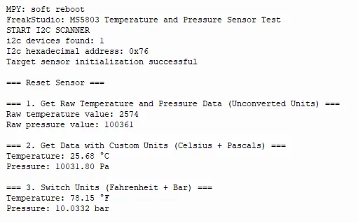
We can see that the temperature and pressure data can be read normally.
IV. Drivers
ms5803-01ba_driver-1.0.1.zip 12 KB
5. BOM & Recommended Alternative Parts
None.
6. Revision History
Document Version | Date of Revision | Modifier | Modified Content |
v1.0 | 2026-03-30 | Ling Gaoxing | Initialize the document |
v1.0.1 | 2026-04-05 | Li Zisheng | The cover photo has not been taken, the production files have not been exported yet, and all other items have been sorted out. |
v1.0.2 | 2026-04-21 | Li Zisheng | The production documents have not been exported yet, and all the rest have been sorted out. |
v1.1 | 2026-04-23 | Xin Ruili | Create an open version of the document based on the internal document version v1.0.2. |
VII. Relevant Materials
7.1 Chip Datasheet
MS5803-01BA.pdf 497 KB
7.2 Unique Icons for PCB Silk Screen