Contents
- I. Module Introduction
- II. Introduction to Main Chips
- 2.1 Chip Overview
- 2.2 Pin Definition
- 2.3 Functional Block Diagram
- 2.4 Performance Parameters
- 2.5 Reference Circuit
- 2.6 Chip Configuration
- 2.7 Communication Interfaces and Related Protocols
- 2.8 PCB Routing Notes
- III. Circuit Engineering
- 3.1 Circuit Source Engineering
- 3.2 Module Usage Instructions
- 3.3 Application Experiment
- IV. Drivers
- 5. BOM & Recommended Alternative Parts
- 6. Revision History
- VII. Relevant Materials
- 7.1 Chip Datasheet
- 7.2 Unique Icons for PCB Silk Screen
I. Module Introduction
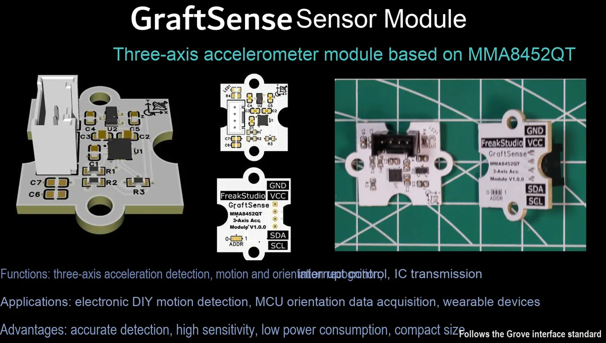
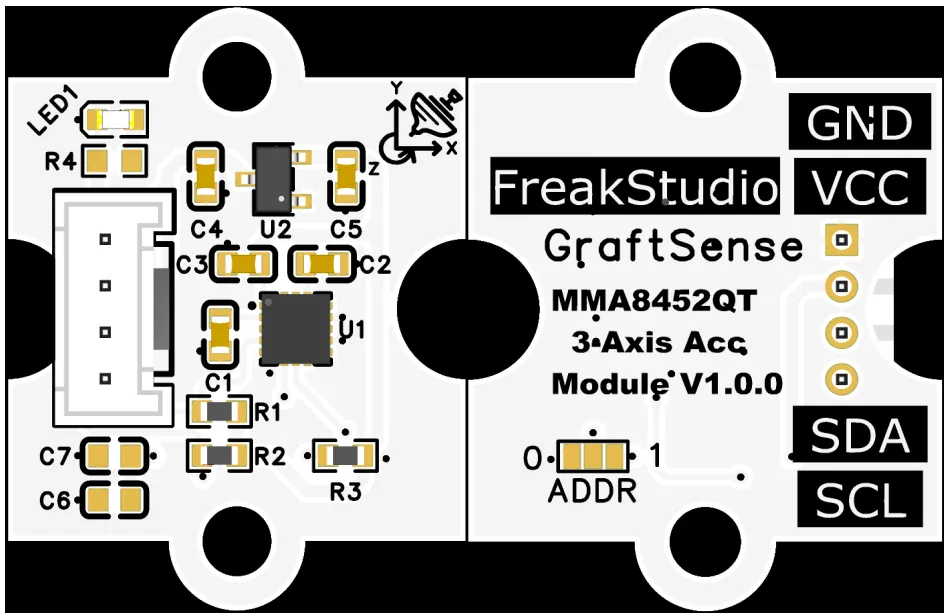
Triaxial acceleration module based on MMA8452QT, adopting the MMA8452QT chip solution, is a low-power triaxial capacitive NXP MEMS Acceleration Sensor launched by NXP. It features a 12-bit high resolution and an 8-bit fast read mode, supports three adjustable ranges of ±2g/±4g/±8g, the output data rate (ODR) covers 0.78Hz to 400Hz, has a built-in high-pass filter and a 32-sample FIFO buffer, and supports orientation recognition, transient detection and automatic wake-up/sleep functions;The module integrates LDO voltage regulator, power filtering and I²C pull-up circuits. The device address can be configured via the ADDR pin as either 0x1C or 0x1D. Equipped with a power indicator, it is compatible with 3.3V level MCUs, and is suitable for high-precision motion detection, attitude sensing, low-power inertial monitoring and other scenarios.
II. Introduction to Main Chips
MMA8452QT is a low-power three-axis capacitive MEMS Acceleration Sensor with 12-bit resolution, supporting ±2g/±4g/±8g measurement ranges, I²C interface, built-in interrupt and automatic wake-up/sleep functions, suitable for motion detection and attitude sensing.
2.1 Chip Overview
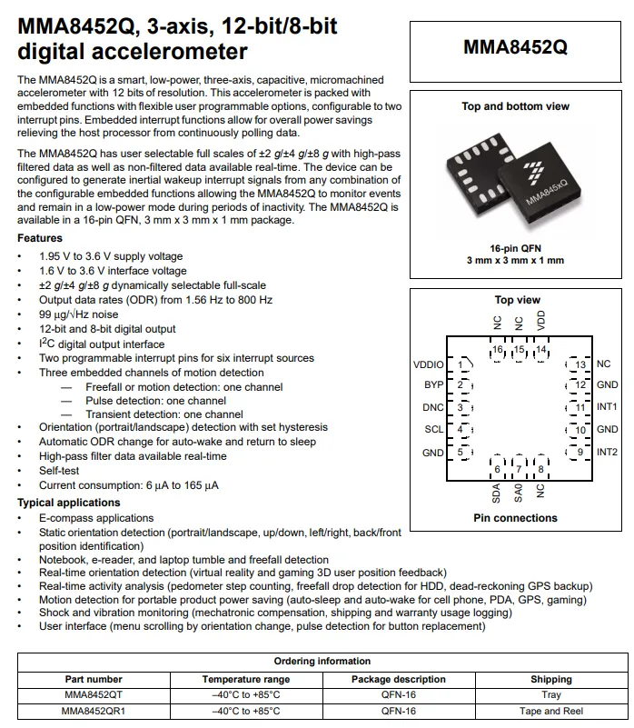
QMC5883P adopts a 16-pin QFN package (3×3×1mm), with a supply voltage of 1.95~3.6V and an interface voltage of 1.6~3.6V;It supports dynamic ranges of ±2g/±4g/±8g, 12-bit/8-bit digital output, an output data rate ranging from 1.56Hz to 800Hz, a noise density of 99μg/√Hz, and features a built-in high-pass filter, self-test function and 32-sample FIFO. It is equipped with two programmable interrupt pins and automatic wake-up/sleep function, with a current consumption of 6~165μA, making it suitable for applications such as electronic compass, attitude detection, free fall detection, step counting and vibration monitoring.
2.2 Pin Definition
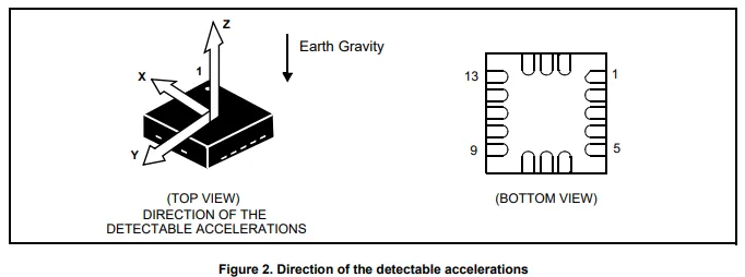
MMA8452Q in the top left view is labeled with the detection directions of the X / Y / Z three-axis accelerometer, and the bottom right view shows the pin layout of the 16-pin QFN package;
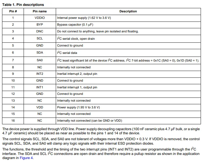
The pinout defines the functions of each pin, including power supply VDD (1.95~3.6V), interface power supply VDDIO (1.62~3.6V), I²C interface SCL / SDA, address configuration SA0 (which determines the I²C address as 0x1C / 0x1D), programmable interrupts INT1 / INT2, as well as the bypass capacitor pin BYP, ground pin GND and no-connect pins DNC / NC;It is also reminded that a decoupling capacitor should be placed close to the power supply, SCL / SDA are open-drain outputs requiring external pull-up resistors, and the voltage of control signals shall not exceed VDDIO + 0.3V.
2.3 Functional Block Diagram
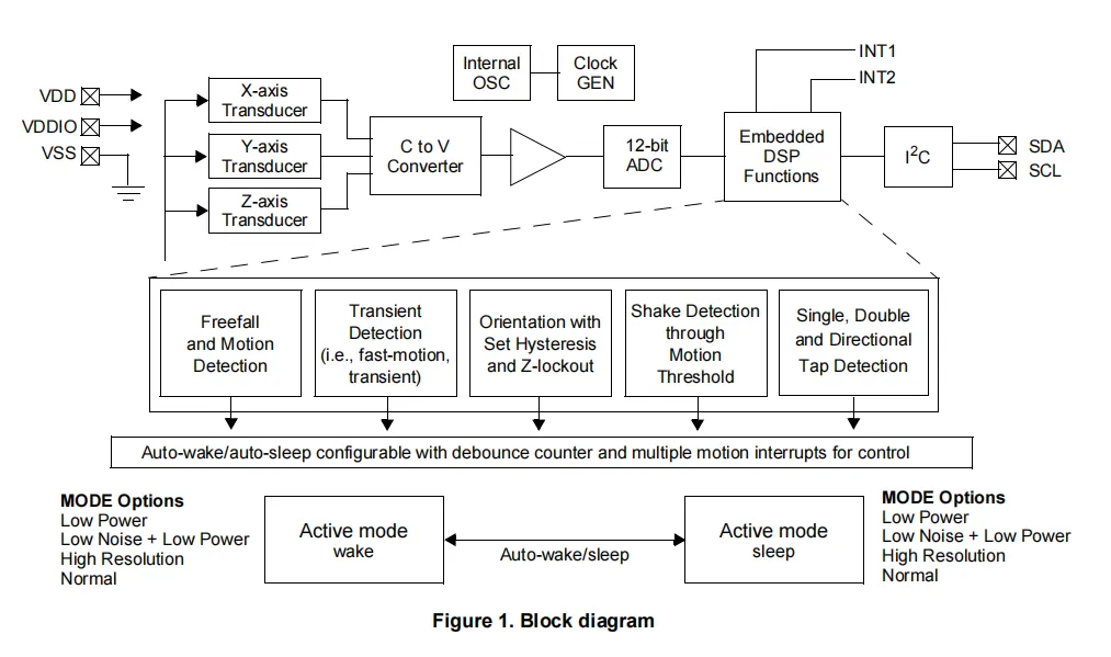
MMA8452Q 's X / Y / Z three-axis capacitive transducer collects acceleration signals, which are converted into analog signals by a capacitance-to-voltage converter, then digitized by a 12-bit ADC, and finally sent to the embedded DSP module for processing;This module integrates functions such as free fall/motion detection, transient detection, orientation recognition, vibration detection and tap detection, and can output event signals through programmable interrupt pins INT1 / INT2. It also supports automatic wake-up/sleep mode to reduce power consumption. The finally processed data communicates with the host via the I²C interface, the internal clock is provided by an on-chip oscillator, and the whole can switch among multiple operating modes including low power consumption, low noise and high resolution.
2.4 Performance Parameters
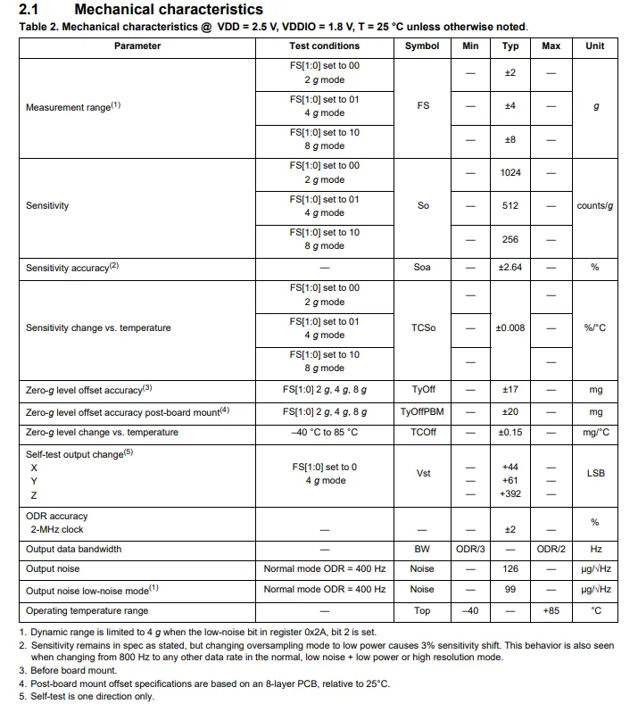
MMA8452Q VDD = 2.5 V, VDDIO = 1.8 V, and 25 °C: it supports three dynamic measurement ranges of ±2 g/±4 g/±8 g, with corresponding sensitivities of 1024/512/256 counts/g, a sensitivity accuracy of ±2.64%, a zero-g offset accuracy of ±17 mg (±20 mg after mounting), an output noise as low as 99 μg/√Hz (low-noise mode), an operating temperature range from -40 °C to + 85 °C, and also covers parameters such as sensitivity temperature drift, self-test output, and ODR accuracy.
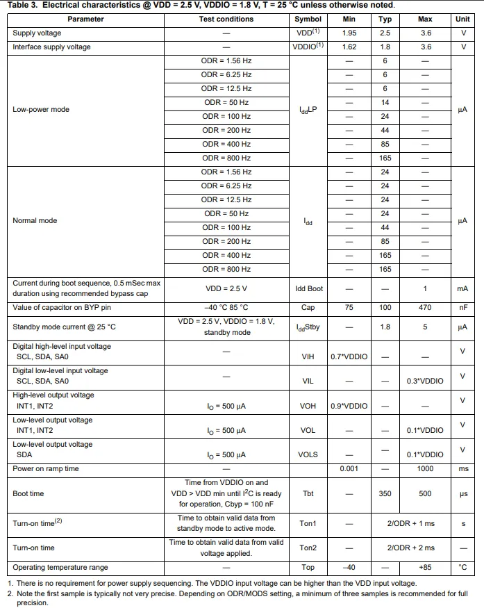
MMA8452Q VDD = 2.5 V, VDDIO = 1.8 V, and at 25 °C: supply voltage range 1.95~3.6 V, interface voltage range 1.62~3.6 V; in low-power mode, the current varies with ODR from 6 μA (1.56 Hz) to 165 μA (800 Hz), the current in normal mode is positively correlated with ODR, and the standby current is only 1.8~5 μA;Digital level compatibility VDDIO proportional threshold, BYP pin capacitance is recommended to be 75~470nF, the startup time includes the power-on ramp, boot and data ready phases, and the operating temperature ranges from -40 to + 85°C.
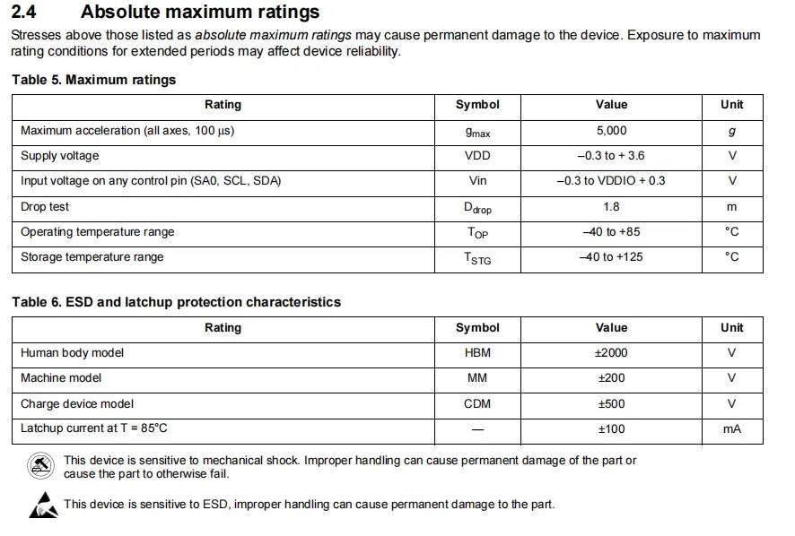
The MMA8452Q has a maximum acceleration tolerance of 5000g (100μs), a VDD voltage tolerance range of -0.3 to 3.6V, a control pin input voltage range of -0.3 to VDDIO plus 0.3V, a drop test height of 1.8m, an operating temperature range of -40 to + 85°C, and a storage temperature range of -40 to + 125°C;ESD protection meets HBM ±2000V, MM ±200V, CDM ±500V, with a latch-up current of ±100mA at 85℃. It is also noted that this device is sensitive to mechanical shock and ESD, and improper operation may cause permanent damage.
2.5 Reference Circuit
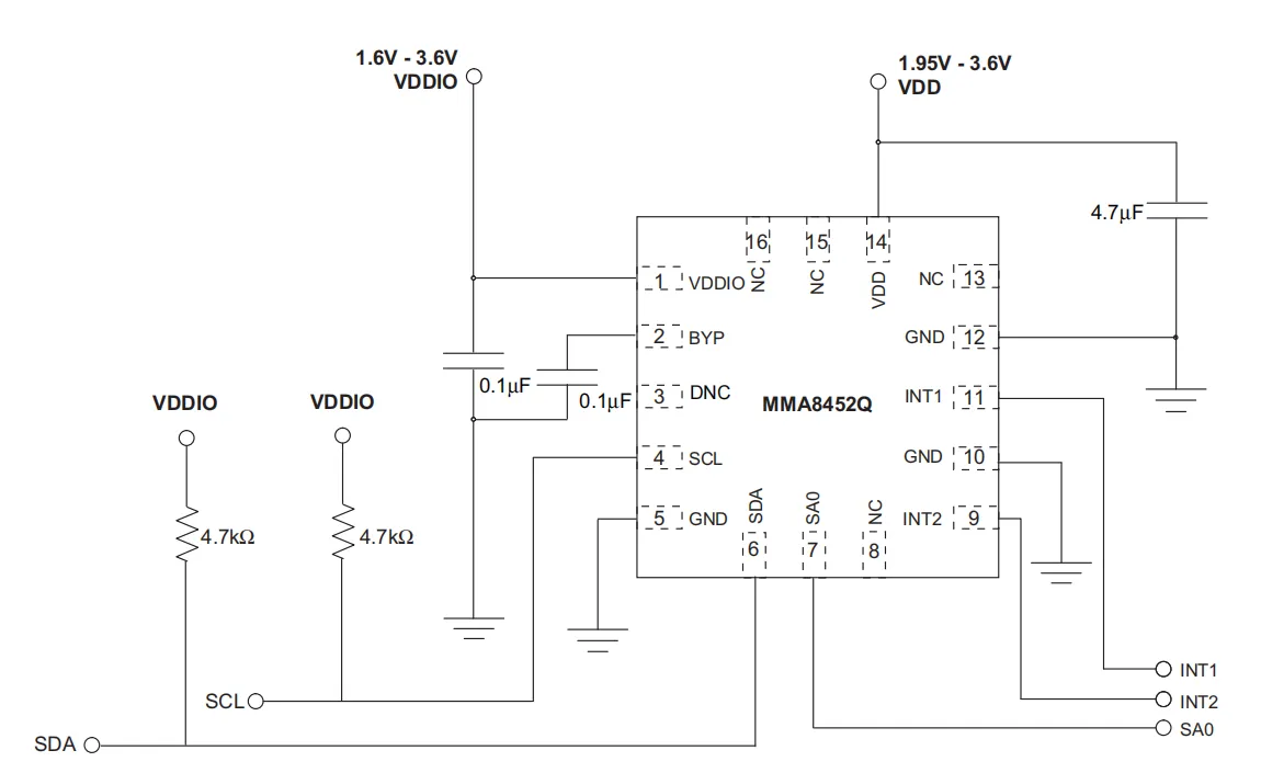
MMA8452Q in practical applications, VDD is connected to a 1.95~3.6V power supply with a 4.7μF decoupling capacitor, VDDIO is connected to a 1.6~3.6V interface power supply with a 0.1μF bypass capacitor, the BYP pin is connected to a 0.1μF capacitor, SCL / SDA pins are each connected to a 4.7kΩ pull-up resistor, INT1 / INT2 serve as interrupt outputs, SA0 is used to configure the I²C address, DNC and NC pins are left floating.
2.6 Chip Configuration
None.
2.7 Communication Interfaces and Related Protocols
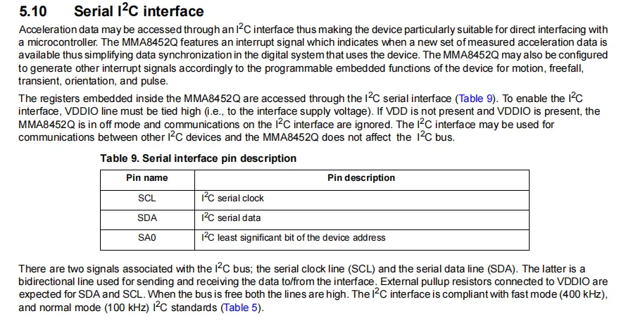
The acceleration data of the MMA8452Q is accessed via the I²C interface with internal registers, which is compatible with both the 100kHz standard mode and 400kHz fast mode. The SCL / SDA pins are open-drain outputs requiring external pull-up resistors; the SA0 pin serves as the least significant bit of the I²C address for configuring the device address. The interface must be powered by VDDIO to be enabled. The chip supports programmable interrupt outputs for data ready, motion, free fall and other events to simplify system data synchronization.
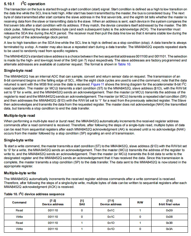
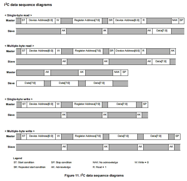
MMA8452Q 's I²C interface supports standard start/stop/repeated start conditions, ACK mechanism, and single-byte/multi-byte read-write operations (the register address auto-increments during multi-byte operations). The SA0 pin can be configured to set the device address to 0x1C or 0x1D (corresponding to read/write addresses 0x38 / 0x39 or 0x3A / 0x3B), and the timing diagram visually illustrates the signal interaction logic between the master and slave devices at each stage.
2.8 PCB Routing Notes
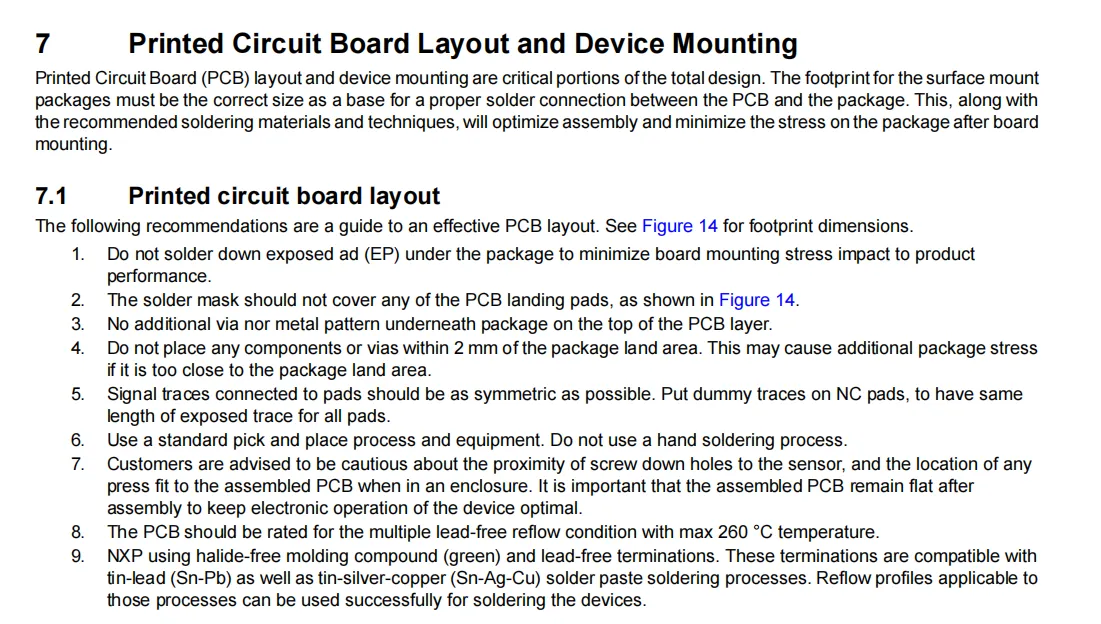
MMA8452Q PCB Layout and Component Mounting Guide: The core requirements include not soldering the bottom exposed pad, not covering the pads with solder mask, no additional vias/metal under the package, and a clearance of ≥2mm between components/vias and the pad area, keeping signal traces as symmetrical as possible, adopting standard SMT mounting process (manual soldering prohibited), PCB must be resistant to 260℃ lead-free reflow soldering. It also notes that PCB stress caused by screw holes/press-fit structures shall be avoided, and the component is compatible with both Sn-Pb and Sn-Ag-Cu solder paste processes.
III. Circuit Engineering
3.1 Circuit Source Engineering
To obtain the circuit source project, please follow the official account [Freak Embedded].
3.2 Module Usage Instructions
The schematic diagram of this module is shown below:
SCH_3-Axis Accelerometer Module Based on MMA8452Q-V1.0.0_2026-03-30.pdf 2.2 MB
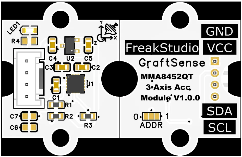
This module provides an I²C communication interface: it supports standard-mode and fast-mode I²C communication, the device address can be flexibly configured to ADDR via the pin as 0x1C or 0x1D, and it is compatible with 3.3V level MCU s;The module integrates LDO voltage regulator, power filtering and I²C pull-up circuits, and is equipped with a power indicator. It can achieve high-precision acceleration detection with ranges of ±2g/±4g/±8g, has a built-in high-pass filter and a 32-sample FIFO buffer, supports direction recognition, transient detection and automatic wake-up/sleep functions. It is suitable for scenarios such as high-precision motion detection, attitude sensing and low-power inertial monitoring, and provides the system with stable and reliable acceleration sensing and data interaction capabilities.
3.3 Application Experiment
Here, we use the GraftPort-RP2040 development board for testing, and the three-axis acceleration module based on MMA8452QT uses the I2C interface to communicate with the main controller.
Here, we first use the HY2.0-4P connection cable to connect the module to the GraftPort-RP2040 development board's I2C0 interface:
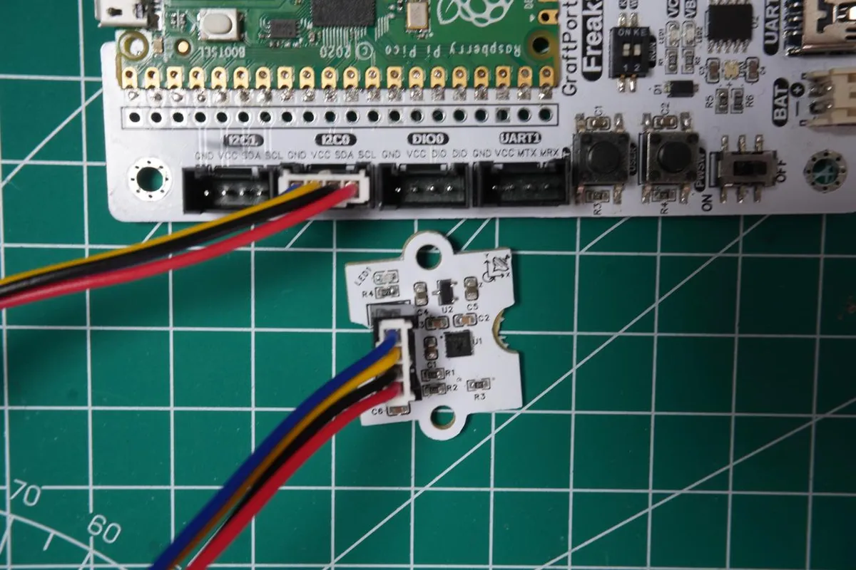
The module connections are shown in the following table:
Development Board Pins | Module Pins | Description |
Pin 4 |
|
|
Pin 5 |
|
|
Here, we need to search for the relevant driver packages on uPyPI: https://upypi.net/zh/
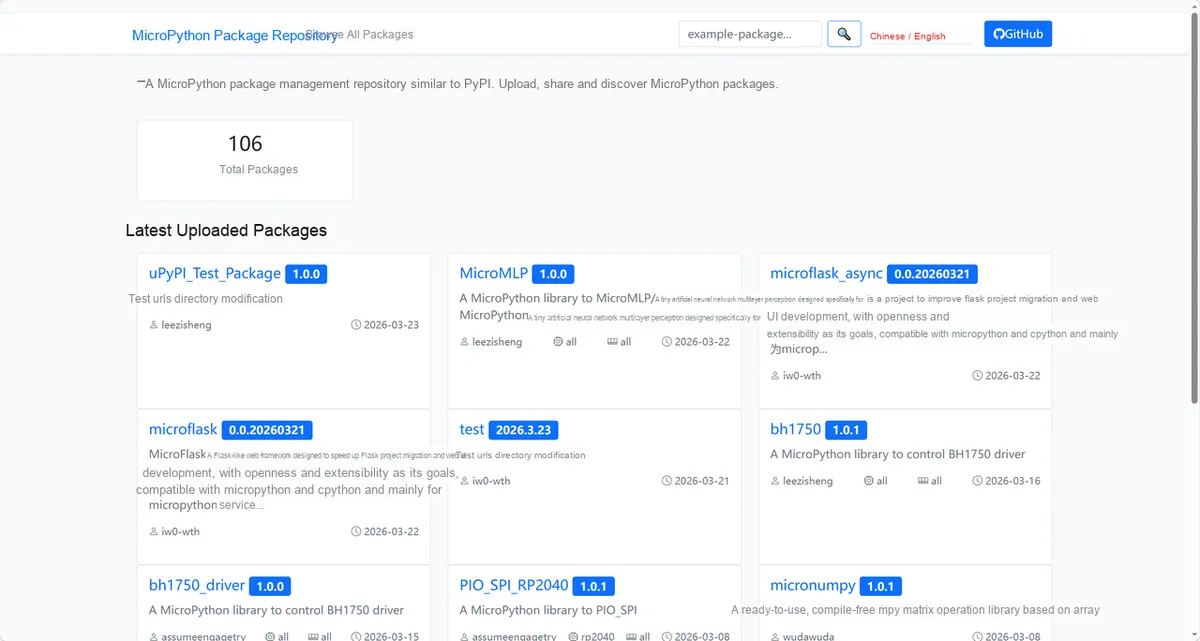
Enter mma8452q_driver to search, and the following will be displayed:
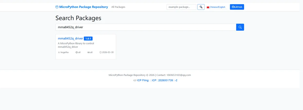
Click to copy the local installation command:
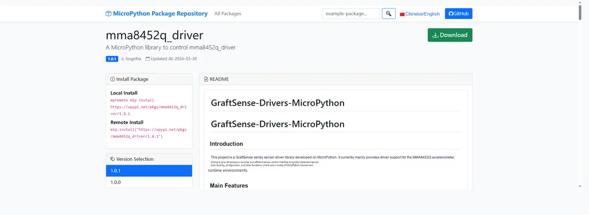
Import the module driver library code via the mip tool. Below are the usage commands for the mpremote tool:
mpremote mip install https://upypi.net/pkgs/mma8452q_driver/1.0.0Import the MicroPython driver code for the MMA8452QT-based 3-axis acceleration module, then copy the following main.py code into our project:
# Python env   : MicroPython v1.23.0
# -*- coding: utf-8 -*-
# @Time    : 2026/3/12 5:20 PM
# @Author  : hogeiha
# @File    : main.py
# @Description : MMA8452Q accelerometer test: configure operating mode, range, data rate and read acceleration data

# ======================================== Import Modules =========================================

import time
from machine import Pin, I2C, SoftI2C
from mma8452q import MMA8452Q

# ======================================== Global Variables ============================================

# I2C configuration for Raspberry Pi Pico
I2C_SCL_PIN = 5
I2C_SDA_PIN = 4
I2C_FREQ = 400000
# Automatically identify the sensor address, define a global target address list (supports multiple addresses; use [] even for a single one)
# MMA8452Q target I2C address (0x1C default, 0x1D if ADDR pin connected to VCC)
TARGET_SENSOR_ADDRS = [0x1C, 0x1D]


# ======================================== Functions ============================================
def print_separator(title):
    """Print separator line to optimize output readability"""
    print("\n" + "=" * 60)
    print(f"=== {title}")
    print("=" * 60)


def safe_read_acceleration(mma):
    """Safely read acceleration data with I2C exception handling"""
    try:
        accx, accy, accz = mma.acceleration
        return (accx, accy, accz), True
    except OSError as e:
        if "EIO" in str(e):
            print(f"  I2C communication error (Errno 5): {e}")
        else:
            print(f"  Failed to read acceleration: {e}")
        return (0.0, 0.0, 0.0), False
    except Exception as e:
        print(f"  Unknown error: {e}")
        return (0.0, 0.0, 0.0), False


def safe_set_param(mma, param_name, value, valid_values):
    """Safely set sensor parameters with validation and exception handling"""
    try:
        if value not in valid_values:
            print(f"  Invalid value {bin(value)}, skip setting")
            return False

        # Set parameter (MMA8452Q driver handles standby/active mode switch internally)
        setattr(mma, param_name, value)
        current_value = getattr(mma, param_name)
        print(f"  Set successfully - Current {param_name}: {current_value} (value: {bin(value)})")
        return True
    except ValueError as e:
        print(f"  Invalid parameter value: {e}")
        return False
    except OSError as e:
        print(f"  I2C error when setting {param_name}: {e}")
        return False
    except Exception as e:
        print(f"  Failed to set {param_name}: {e}")
        return False


# ======================================== Custom Classes ============================================

# ======================================== Initialization configuration ===========================================
time.sleep(3)
print("FreakStudio: MMA8452Q accelerometer configuration and data reading demo")

# Initialize I2C bus
try:
    # I2C initialization (compatible with I2C/SoftI2C)
    i2c_bus = SoftI2C(sda=Pin(I2C_SDA_PIN), scl=Pin(I2C_SCL_PIN), freq=I2C_FREQ)

    # Start scanning for devices on the I2C bus
    devices_list: list[int] = i2c_bus.scan()
    print("START I2C SCANNER")

    # Check the I2C device scan result
    if len(devices_list) == 0:
        print("No i2c device !")
        raise SystemExit("I2C scan found no devices, program exited")
    else:
        print("i2c devices found:", len(devices_list))

    # Iterate over the address list to initialize the target sensor
    mma_sensor = None  # Placeholder for the sensor object initialization
    for device in devices_list:
        if device in TARGET_SENSOR_ADDRS:
            print("I2c hexadecimal address:", hex(device))
            try:
                # Automatically identify and initialize the corresponding sensor
                mma_sensor = MMA8452Q(i2c_bus, address=device)
                print("Sensor initialization successful")
                break
            except Exception as e:
                print(f"Sensor Initialization failed: {e}")
                continue
    else:
        # Target device not found, raise an exception
        raise Exception("No target sensor device found in I2C bus")


except Exception as e:
    print(f"Initialization error: {e}")
    raise SystemExit("Program exited due to initialization failure")

# ========================================  Main Program  ============================================
if __name__ == "__main__":
    # 1. Demonstrate operation mode configuration (standby/active)
    print_separator("1. Operation Mode Configuration Demo")
    for mode in MMA8452Q.operation_mode_values:
        if safe_set_param(mma_sensor, "operation_mode", mode, MMA8452Q.operation_mode_values):
            acc_data, success = safe_read_acceleration(mma_sensor)
            if success:
                accx, accy, accz = acc_data
                print(f"    Acceleration: X={accx:0.1f} m/s², Y={accy:0.1f} m/s², Z={accz:0.1f} m/s²")
            else:
                print(f"    [Cannot read data in standby mode]")
        time.sleep(1)

    # Restore active mode for subsequent demos
    safe_set_param(mma_sensor, "operation_mode", MMA8452Q.ACTIVE_MODE, MMA8452Q.operation_mode_values)

    # 2. Demonstrate acceleration scale range configuration (2G/4G/8G)
    print_separator("2. Acceleration Scale Range Configuration Demo")
    for scale in MMA8452Q.scale_range_values:
        if safe_set_param(mma_sensor, "scale_range", scale, MMA8452Q.scale_range_values):
            acc_data, success = safe_read_acceleration(mma_sensor)
            if success:
                accx, accy, accz = acc_data
                print(f"    Acceleration: X={accx:0.1f} m/s², Y={accy:0.1f} m/s², Z={accz:0.1f} m/s²")
        time.sleep(1)

    # 3. Demonstrate output data rate configuration (800Hz ~ 1.56Hz)
    print_separator("3. Output Data Rate Configuration Demo")
    for dr in MMA8452Q.data_rate_values:
        if safe_set_param(mma_sensor, "data_rate", dr, MMA8452Q.data_rate_values):
            # Read data 3 times to observe different data rate effects
            print("    Continuous 3 readings:")
            for _ in range(3):
                acc_data, success = safe_read_acceleration(mma_sensor)
                if success:
                    accx, accy, accz = acc_data
                    print(f"      X={accx:0.1f}, Y={accy:0.1f}, Z={accz:0.1f} m/s²")
                time.sleep(0.2)
        time.sleep(0.5)

    # 4. Demonstrate high pass filter switch configuration (enable/disable)
    print_separator("4. High Pass Filter Switch Configuration Demo")
    for hpf in MMA8452Q.high_pass_filter_values:
        if safe_set_param(mma_sensor, "high_pass_filter", hpf, MMA8452Q.high_pass_filter_values):
            acc_data, success = safe_read_acceleration(mma_sensor)
            if success:
                accx, accy, accz = acc_data
                print(f"    Acceleration: X={accx:0.1f} m/s², Y={accy:0.1f} m/s², Z={accz:0.1f} m/s²")
        time.sleep(1)

    # Enable high pass filter first, then demonstrate cutoff frequency
    safe_set_param(mma_sensor, "high_pass_filter", MMA8452Q.HPF_ENABLED, MMA8452Q.high_pass_filter_values)

    # 5. Demonstrate high pass filter cutoff frequency configuration (16Hz/8Hz/4Hz/2Hz)
    print_separator("5. High Pass Filter Cutoff Frequency Configuration Demo")
    for cutoff in MMA8452Q.high_pass_filter_cutoff_values:
        if safe_set_param(mma_sensor, "high_pass_filter_cutoff", cutoff, MMA8452Q.high_pass_filter_cutoff_values):
            acc_data, success = safe_read_acceleration(mma_sensor)
            if success:
                accx, accy, accz = acc_data
                print(f"    Acceleration: X={accx:0.1f} m/s², Y={accy:0.1f} m/s², Z={accz:0.1f} m/s²")
        time.sleep(1)

    # Final status summary
    print_separator("6. Sensor Final Configuration Summary")
    try:
        print(f"Operation Mode: {mma_sensor.operation_mode}")
        print(f"Acceleration Scale Range: {mma_sensor.scale_range}")
        print(f"Output Data Rate: {mma_sensor.data_rate}")
        print(f"High Pass Filter Status: {mma_sensor.high_pass_filter}")
        print(f"High Pass Filter Cutoff Frequency: {mma_sensor.high_pass_filter_cutoff}")

        acc_data, success = safe_read_acceleration(mma_sensor)
        if success:
            accx, accy, accz = acc_data
            print(f"Current Acceleration: X={accx:0.1f} m/s², Y={accy:0.1f} m/s², Z={accz:0.1f} m/s²")
    except Exception as e:
        print(f"Failed to read final configuration: {e}")

    print("\n=== Demo completed ===")
In the code above, we sequentially demonstrate and test the configuration of parameters such as the sensor's operating mode, acceleration measurement range, output data rate, high-pass filter switch and cutoff frequency, read and print the three-axis acceleration data in real time, and finally output the sensor's final configuration and current acceleration values, completing the full-parameter configuration verification and functional test for this accelerometer.
Burn the code, open the terminal, and the output is as follows:
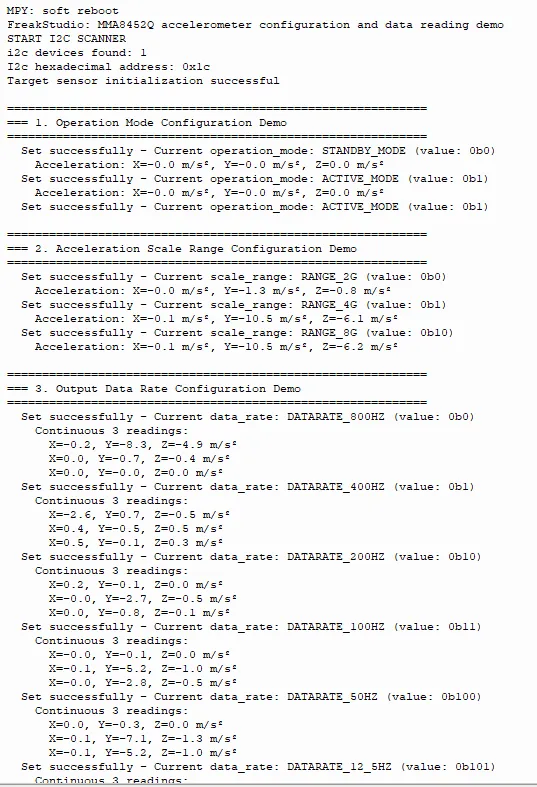
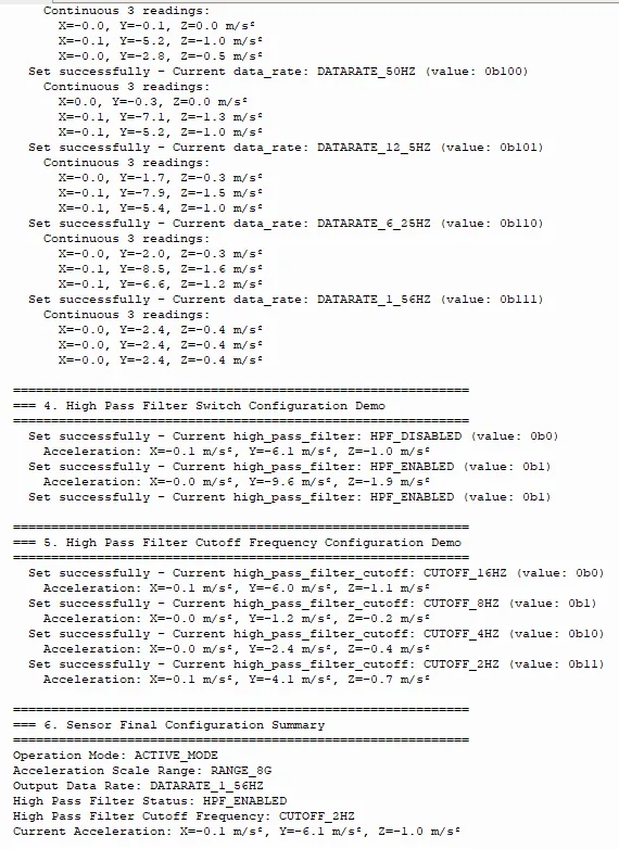
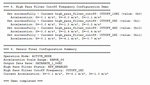
We can see that the relevant functional tests can be completed normally.
IV. Drivers
mma8452q_driver-1.0.1.zip 16 KB
5. BOM & Recommended Alternative Parts
None.
6. Revision History
Document Version | Date of Revision | Modifier | Modified Content |
v1.0 | 2026-03-30 | Ling Gaoxing | Initialize the document |
v1.0.1 | 2026-04-05 | Li Zisheng | The homepage photo has not been taken, the production files have not been exported yet, and all other items have been sorted out completely. |
v1.0.2 | 2026-04-21 | Li Zisheng | The production documents have not been exported yet, while all the others have been sorted out completely. |
v1.1 | 2026-04-23 | Xin Ruili | Create an open version of the document, based on the internal document version v1.0.2. |
VII. Relevant Materials
7.1 Chip Datasheet
MMA8452Q.pdf 487 KB
7.2 Unique Icons for PCB Silk Screen