Contents
- I. Module Introduction
- II. Introduction to Main Chips
- 2.1 Chip Overview
- 2.2 Pin Definition
- 2.3 Functional Block Diagram
- 2.4 Performance Parameters
- 2.5 Reference Circuit
- 2.6 Chip Configuration
- 2.7 Communication Interfaces and Related Protocols
- 2.8 PCB Routing Precautions
- III. Instructions for Circuit Engineering and Module Usage
- 3.1 Circuit Source Engineering
- 3.2 Module Usage Instructions
- 3.3 Application Experiment
- IV. Drivers
- 5. BOM & Recommended Alternative Parts
- VI. Revision History
- VII. Relevant Materials
- 7.1 Chip Datasheet
- 7.2 Unique Icons for PCB Silk Screen
I. Module Introduction
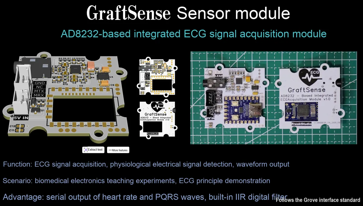
The integrated ECG signal acquisition module based on AD8232 is an integrated ECG acquisition module based on AD8232 and RP2040 main controller, which achieves high-precision ECG signal capture at a fixed 100Hz sampling rate. Its core highlight lies in the professional filtering scheme built into the RP2040: through DC removal preprocessing with a sliding window, paired with three-stage cascaded IIR digital filtering and amplitude calibration, it can effectively suppress various types of interference and output ECG signals that are both stable and accurate.
The core functions are as follows:
- ECG Acquisition and Processing: ECG potential difference is acquired via electrodes on both arms, conditioned by the
AD8232, then subjected to the full-process data processing including filtering and calibration by theRP2040, to output both the original and filtered ECG waveforms. - Flexible Data Interaction:
UARTserial port supports both active reporting and passive query modes. The active reporting frequency can be switched between 50Hz and 100Hz (100Hz by default), which can output heart rate value, lead-off status, module working status, and support controlling the start and stop ofAD8232. - Reliable Power Supply Management: Supports dual power supply modes, namely 5V external battery power supply and the
Type-Cpower supply for RP2040-Zero, and integrates reverse connection protection, sleep control, 5V-to-3.3V circuit, as well as power filtering and indicator light. - High Compatibility and Ease of Use: Compliant with the
Groveinterface standard, it features Plug and Play, requires no additional data processing for the integrated main control, and supports convenient debugging.
Compared with the traditional AD8232 module, this module has the following advantages:
- Higher integration: Built-in RP2040 main control chip, a single module can complete the whole process of acquisition, processing and output;
- Stronger anti-interference capability: Three-level IIR digital filtering + amplitude calibration actively suppresses power frequency, baseline drift and myoelectric noise; traditional modules only rely on hardware filtering, which has weak anti-interference performance and requires secondary software processing.
- More flexible interaction and control: It supports dual modes of active reporting and passive query, enabling remote control of module status; whereas traditional modules can only output raw signals with no active interaction capability.
- Better ease of use: It complies with the Grove interface standard, integrates power management and status indication, and is Out Of The Box; while traditional modules require users to design power supply, interface and debugging circuits on their own, which sets a higher threshold.
This module is applicable to scenarios such as biomedical electronics teaching and electrocardiogram principle demonstration, and has the dual values of stable acquisition and convenient debugging.
II. Introduction to Main Chips
AD8232 is a dedicated single-lead ECG signal conditioning chip launched by ADI. It operates on a single 2.0~3.5V power supply with low power consumption, integrates an instrumentation amplifier, filter circuit and lead-off detection, supports 2/3 electrode configurations, can accurately extract and amplify weak ECG signals, and is designed specifically for low-power medical devices such as portable and wearable ECG monitors.
2.1 Chip Overview
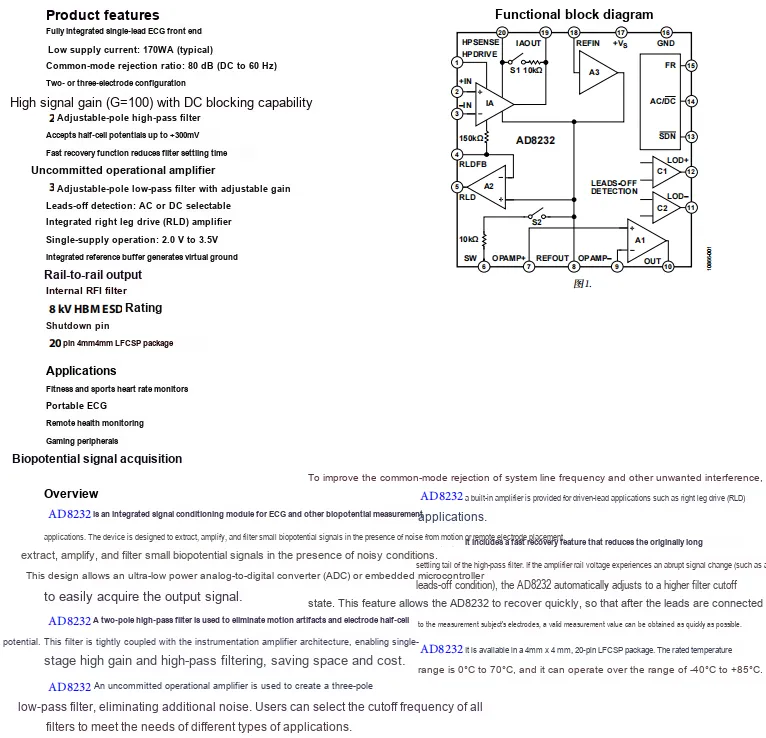
AD8232 is a dedicated single-lead ECG signal conditioning chip launched by ADI. It operates on a single 2.0~3.5V power supply, with a typical quiescent current of only 170μA. The chip integrates an instrumentation amplifier with a gain of 100, a dual-pole high-pass filter, a lead-off detection circuit, and a right-leg drive amplifier, supporting 2 or 3-electrode configurations. It can accurately extract, amplify and filter weak ECG signals in noisy environments such as during exercise, and can also construct a three-pole low-pass filter via an unused operational amplifier. Featuring a high common-mode rejection ratio and fast recovery function, it is suitable for low-power wearable scenarios including portable ECG monitors, fitness heart rate devices, and remote health monitoring, and adopts a 20-pin LFCSP package.
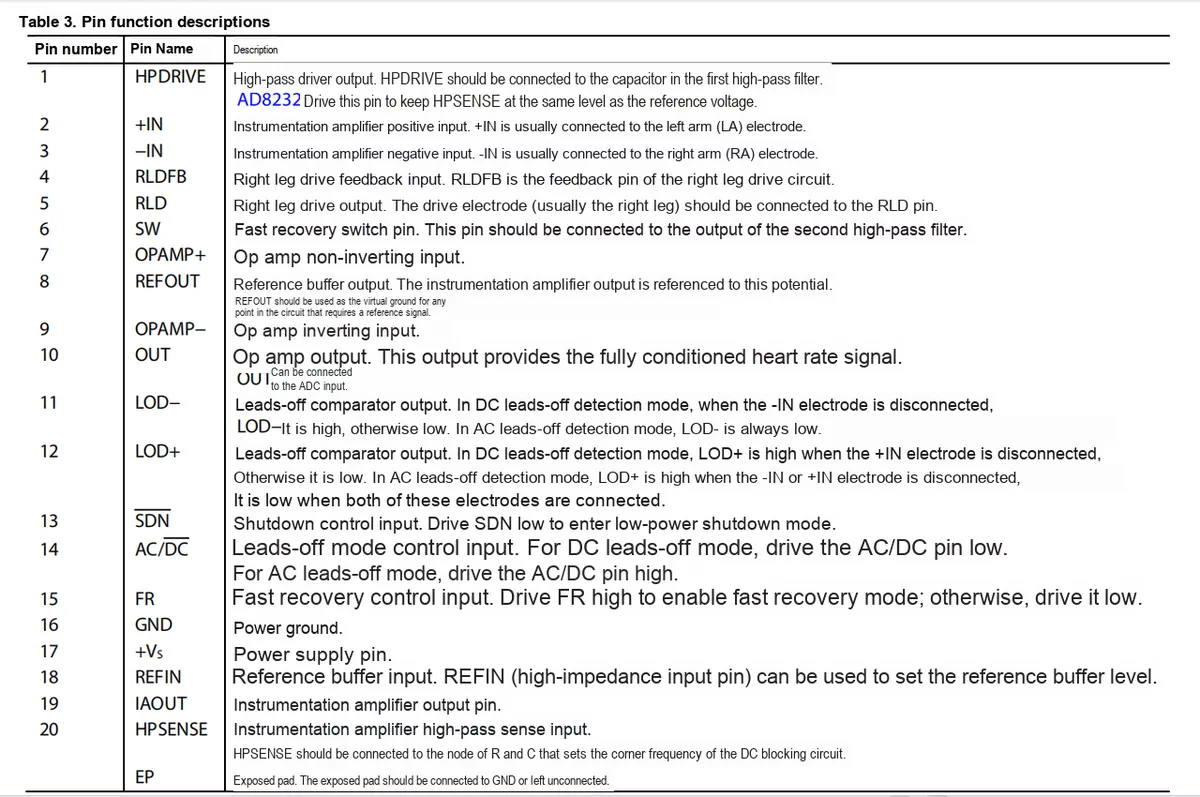
2.2 Pin Definition
2.3 Functional Block Diagram
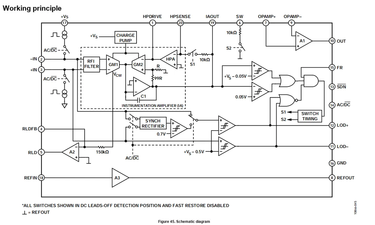
AD8232 features an RFI -filtered instrumentation amplifier (IA) as its core, adapts to AC and DC input signals via an AC / DC switch, and uses a charge pump to power the high-voltage drive module for electrode driving. The chip integrates a lead-off detection circuit that monitors the electrode connection status in real time through a synchronous rectifier and a comparator, and switches operating modes via a switch timing control module;The input signal is amplified by the instrumentation amplifier, then processed and output by the configurable gain network and the output operational amplifier. Meanwhile, it also integrates auxiliary functions such as reference voltage buffering, fast recovery and shutdown, which can realize high-interference-resistance acquisition, amplification and condition monitoring of physiological signals.
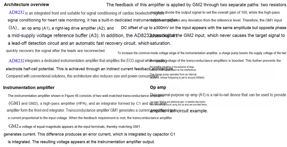
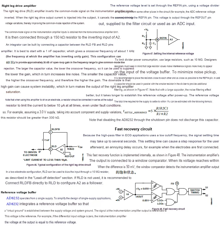
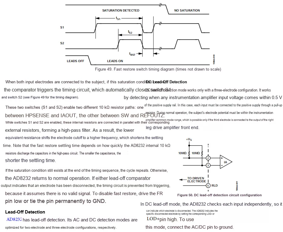
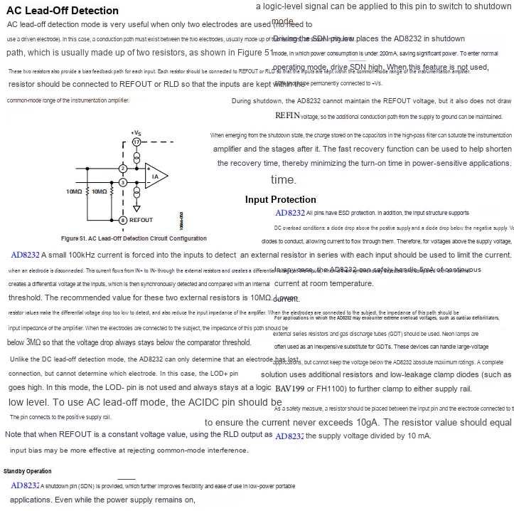
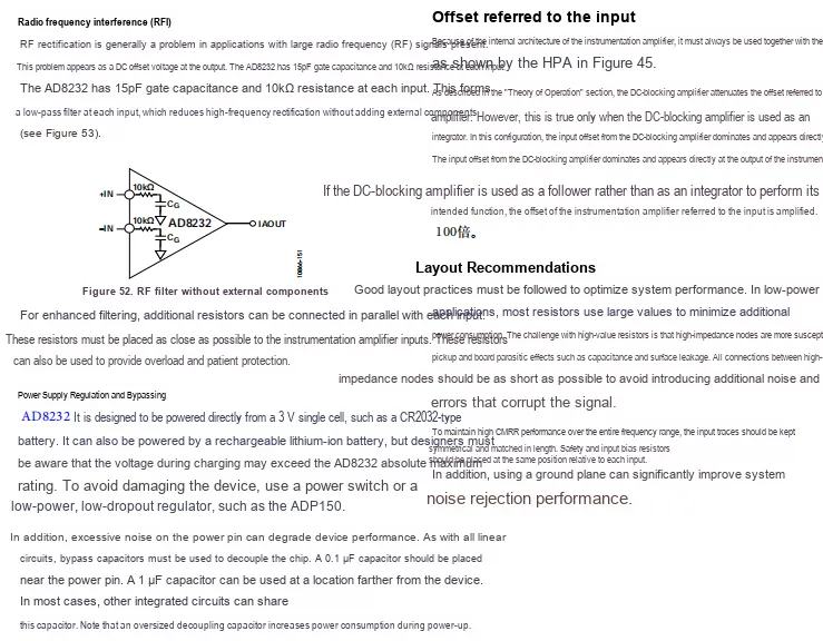
AD8232 adopts a dedicated instrumentation amplifier as its core, and amplifies weak ECG signals via an indirect current feedback architecture consisting of a transconductance amplifier and a DC-blocking amplifier, while suppressing electrode half-cell potential and common-mode noise; it also utilizes a charge pump to expand the common-mode voltage range to prevent saturation. The right-leg drive amplifier injects a reverse current to cancel common-mode interference, further improving noise immunity; the reference voltage buffer creates a virtual ground to provide a stable reference for signals.When signal saturation or lead-off is detected, the fast recovery circuit switches the resistor path to shorten the signal settling time, while the lead-off detection function monitors the electrode connection status via AC or DC mode; in addition, the unused operational amplifier can also be used to construct an additional low-pass filter, which collectively realizes accurate conditioning and reliable acquisition of ECG signals.
2.4 Performance Parameters
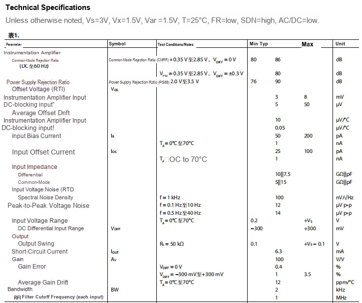
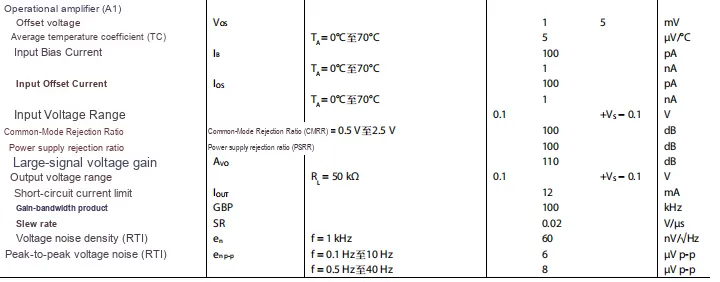
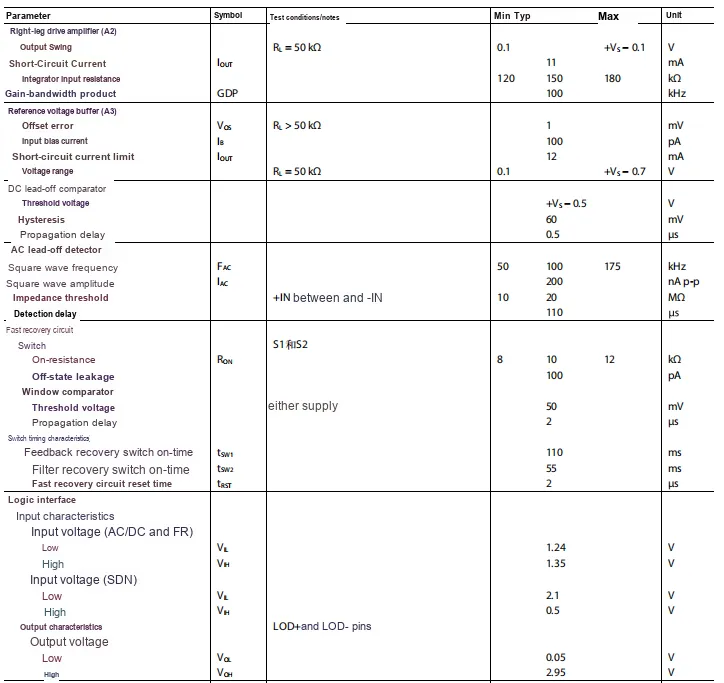
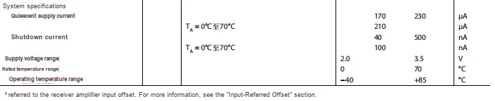
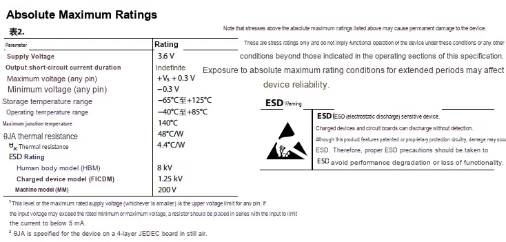
AD8232 's performance parameters cover core modules and system characteristics: with a typical 3V power supply, the instrumentation amplifier has a typical common-mode rejection ratio of 86dB, a typical input offset voltage of 5μV, a fixed gain of 100, a typical bandwidth of 1kHz, and an input noise of 14μVp-p over the 0.5Hz to 40Hz bandwidth; both the operational amplifier and the right-leg drive amplifier feature low offset and high gain-bandwidth characteristics;The typical quiescent current of the system is only 170μA, it supports a wide power supply voltage range of 2.0~3.5V, and the operating temperature ranges from -40℃ to + 85℃; in terms of absolute ratings, the upper limit of the power supply voltage is 3.6V, and it has an 8kV human body model ESD protection capability, whose overall parameters adapt to the requirements of low-power, high-precision ECG signal conditioning.
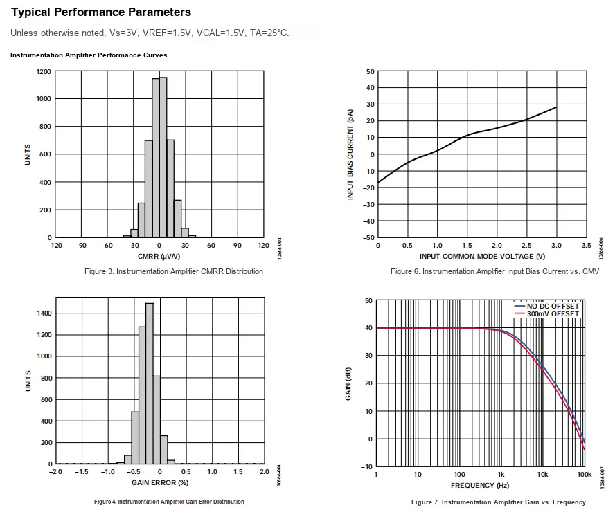
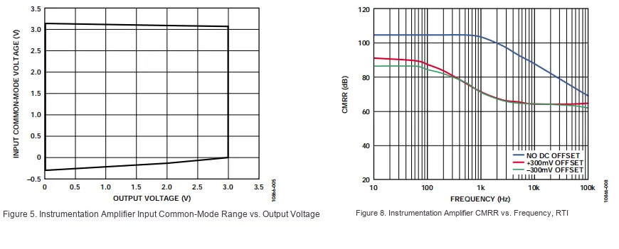
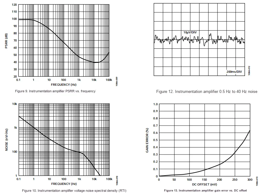
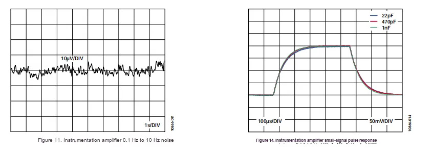
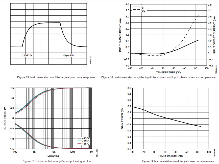
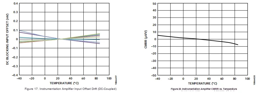
The instrumentation amplifier performance curves of AD8232 demonstrate its excellent suitability for ECG signal conditioning:
- Parameter Consistency and Accuracy:
CMRRand gain error are concentrated in distribution, indicating that the devices feature excellent inter-device performance consistency and high gain accuracy. - Anti-interference and common-mode characteristics: wide input common-mode range, with bias current barely affected by common-mode voltage; excellent performance in low-frequency
CMRRandPSRR, which can effectively suppress common-mode noise and power supply noise, and the attenuation in the high-frequency band will not interfere with the processing of electrocardiogram (ECG) signals (0.05~100Hz). - Frequency and Noise Characteristics: The gain stabilizes at 100 times at low frequencies, exhibits low-pass attenuation as frequency increases, and matches the bandwidth of ECG signals; it features a low noise level (approximately 14μVp-p within the 0.5~40Hz bandwidth) that attenuates with increasing frequency, making it suitable for extracting weak bioelectrical signals.
- Dynamic and Temperature Stability: It features a fast pulse response speed to accurately capture ECG waveforms; its input bias current, offset drift, gain error and other parameters are barely affected by temperature, ensuring stable operation in various environments.
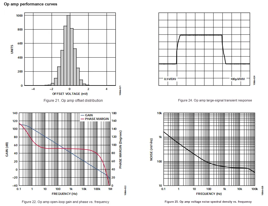
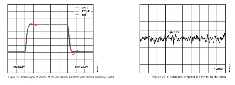
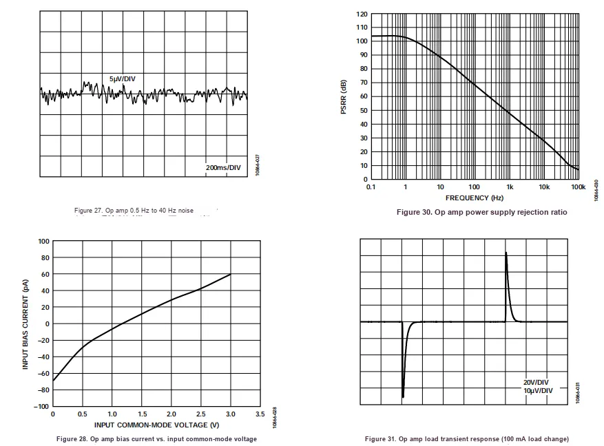
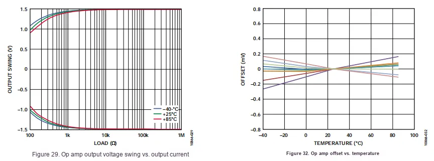
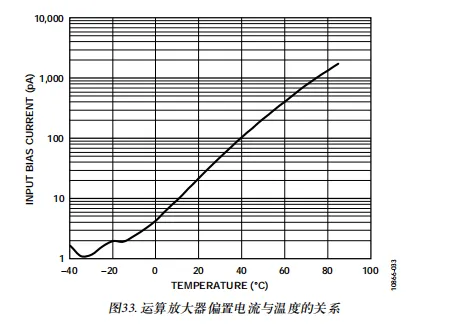
AD8232 The performance curve of its built-in operational amplifier reflects its excellent characteristics suitable for ECG signal processing:
- Accuracy and Consistency: The offset voltage is distributed around 0mV, with excellent inter-device performance consistency, which can reduce signal errors.
- Stability and Dynamic Response: The open-loop gain is high in the low-frequency band with sufficient phase margin, endowing the circuit with excellent stability; it features fast transient response for both small and large signals as well as small overshoot, making it suitable for constructing additional low-pass filtering circuits to optimize ECG signals.
- Low-noise characteristics: The voltage noise density decreases as the frequency increases, delivering an extremely low noise level within the ECG signal bandwidth of 0.5Hz to 40Hz, which prevents interference with weak bioelectrical signals.
- Anti-interference and Load Capability: High power supply rejection ratio (PSRR) in the low-frequency band, which can effectively suppress power supply noise; the output voltage responds stably when the load changes, with strong anti-disturbance capability.
- Temperature Stability: The offset voltage and input bias current exhibit minimal variation with temperature, ensuring consistent performance across diverse operating environments; the output swing is close to the power supply rails, providing sufficient dynamic range to adapt to low-voltage power supply scenarios.
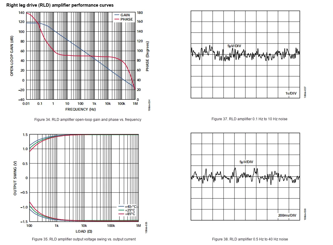
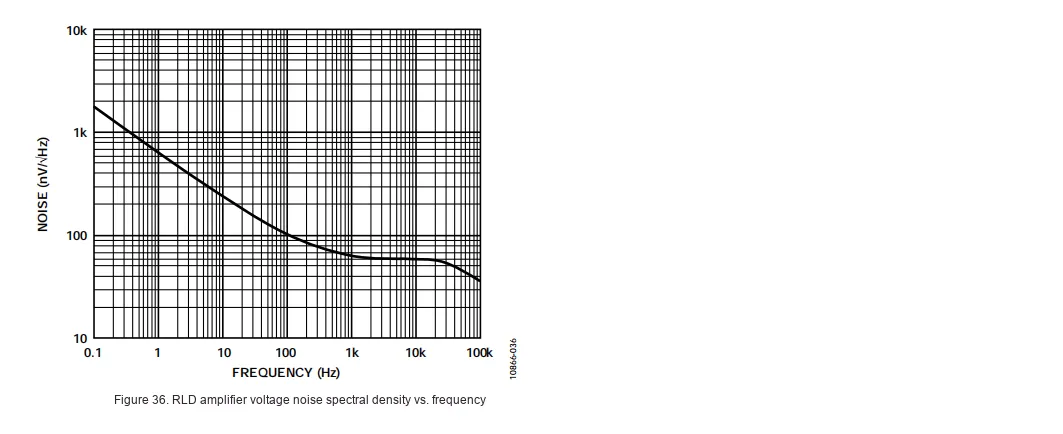
AD8232 Right Leg Drive (RLD) amplifier performance curve, which reflects its key role in suppressing common-mode interference and ensuring the quality of ECG signals:
- Stability: The open-loop gain is high in the low-frequency band with sufficient phase margin, so the circuit features excellent stability and can reliably inject reverse current to cancel out the common-mode noise from the human body.
- Dynamic Range: The output swing is close to the power supply rail, which adapts to low-voltage power supply scenarios, can effectively drive the right leg electrode, and ensures the strength of common-mode rejection.
- Low Noise Characteristics: The voltage noise density decreases as the frequency increases, and the noise level is extremely low within the electrocardiogram (ECG) signal bandwidth from 0.5 Hz to 40 Hz, which prevents its own noise from interfering with the weak ECG signals.
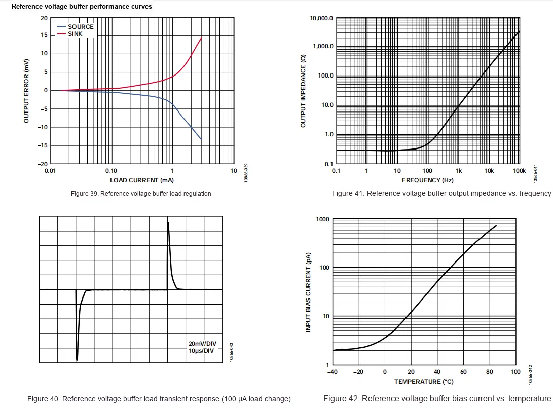
AD8232 reference voltage buffer performance curve reflects its key capability to provide a stable virtual ground for ECG signal conditioning:
- Load Stability: The load regulation curve shows that the output error is extremely small within the range of low load current, indicating that the output voltage remains stable when the load changes, which can reliably maintain the virtual ground reference.
- Dynamic Response: It features fast load transient response and small overshoot, which can quickly respond to load fluctuations and prevent transient interference from occurring in the reference voltage.
- Output Impedance Characteristics: The output impedance is extremely low in the low-frequency band, which adapts to the low-frequency characteristics of ECG signals and ensures that the reference voltage is not affected by load fluctuations; the increase in impedance in the high-frequency band does not affect ECG signal processing.
- Temperature Stability: The bias current increases slightly with rising temperature, but its overall magnitude is negligible, and its impact on the accuracy of the reference voltage can be ignored, ensuring stable operation in different environments.
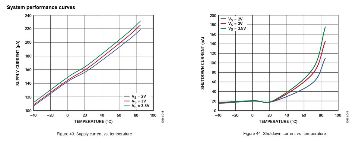
AD8232 's system performance curves mainly reflect its core feature of low power consumption:
- Operating supply current: At the three supply voltages of 2V, 3V and 3.5V, the supply current increases linearly with rising temperature, yet remains at a low level ranging from 100 to 230μA as a whole. It maintains low power consumption even in high-temperature environments, adapting to the battery life requirements of portable devices.
- Shutdown Current: When the chip is in shutdown state, the current is only at the nA level and rises slightly with increasing temperature, yet the overall power consumption is extremely low, which can effectively extend the battery life of the device in standby or sleep mode.
2.5 Reference Circuit
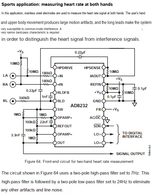
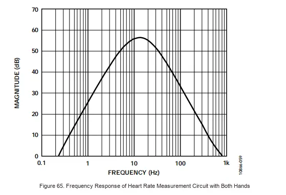
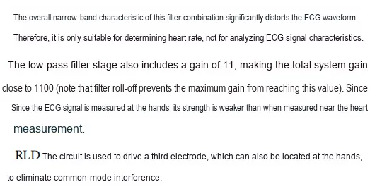
This AD8232 reference circuit is specifically designed for bi-hand heart rate measurement in sports scenarios: it takes AD8232 as the core, and builds a 7Hz two-pole high-pass filter and a 24Hz two-pole low-pass filter via external resistors and capacitors to form a narrow-band filtering characteristic, thereby suppressing motion artifacts and common-mode interference; meanwhile, it integrates an RLD (right leg drive) circuit to further cancel common-mode noise, and the low-pass filter can also provide additional gain to amplify the weak ECG signal measured from both hands.Its narrowband frequency response is only suitable for heart rate determination and cannot support complete ECG waveform analysis, and its overall design adapts to the needs of heart rate monitoring in sports scenarios.
2.6 Chip Configuration
None.
2.7 Communication Interfaces and Related Protocols
None.
2.8 PCB Routing Precautions
III. Instructions for Circuit Engineering and Module Usage
3.1 Circuit Source Engineering
To obtain the source project of the circuit, please follow the official account [Freak Embedded].
3.2 Module Usage Instructions
The schematic diagram of this module is shown below:
SCH_AD8232-Based Integrated ECG Signal Acquisition Module-v1.0.pdf 2.9 MB
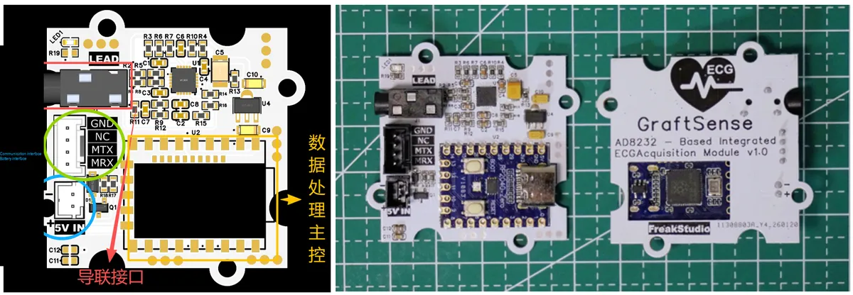
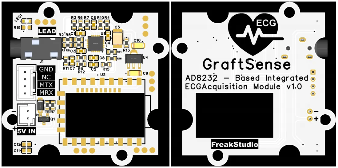
This module provides a serial port UART interface MRX and MTX: here M stands for the host, meaning it is the MCU 's RX corresponding to the module' s TX, so as to realize bidirectional data transmission between the module and the host computer.
The module is equipped with 5V IN 's PH2.0-2P terminals, which provide 5V input for the entire module; it also supports power supply via the RP2040-Zero ' s Type-C interface. To avoid power frequency noise introduced by the USB interface and improve the quality of ECG signals, it is recommended to prioritize power supply using a battery plus a boost unit.
Lead interface LEAD, serving as the input channel for ECG signals, is used to connect lead wires. If you have high requirements for waveform accuracy, it is recommended to replace it with shielded lead wires to further reduce electromagnetic interference.
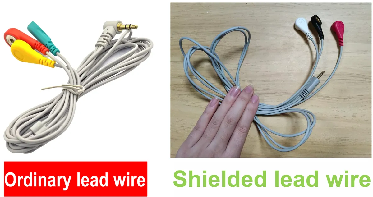
In practical use, simply connect a 5V power supply (or power via a battery + boost unit) to the module, and connect the lead wires to the LEAD interface, then the module can work with the UART communication interface to complete ECG signal acquisition and data transmission.
3.2.1 Introduction to ECG Electrocardiogram Signals
You can think of an ECG as the "electrical activity diary" of the heart, which records the electrical signals generated with each heartbeat in the form of waveforms. Just like the red grid waveform on the left in the figure, each up-and-down fluctuation corresponds to a "discharge-contraction" process of the heart. Through this "diary", doctors can tell whether your heartbeat is regular and your heart rate is normal, help you screen for heart problems such as arrhythmia and myocardial infarction, and even evaluate the working status of the pacemaker.
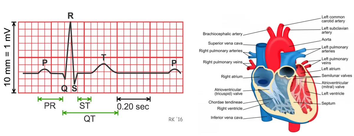
The waveform in the diagram is divided into several key segments, each corresponding to a specific "action" of the heart:
- The first small bump that appears is the
Pwave, which represents the contraction of the heart's "upper chambers"(the atria) as they pump blood into the "lower chambers"(the ventricles). - Immediately following the tall, sharp
QRScomplex — the most prominent component of the entire waveform — is a small initial downward deflection called theQwave, a tall upward peak known as theRwave, and another subsequent downward deflection referred to as theSwave. This set of waves represents the rapid ventricular contraction that pumps blood throughout the body, and it also corresponds to the most forceful phase of the heartbeat. - The final gentle small bump is the
Twave, which represents the relaxation and "recharging" of the ventricles after contraction to prepare for the next beat.
By observing the shape, interval and height of these waveforms, doctors can detect "abnormal signals" of the heart. For example, an excessively long interval from the P wave to the QRS complex may indicate that the electrical signal transmission from the atria to the ventricles is slowed down; an overly wide QRS complex may suggest a problem with ventricular contraction; an abnormal T wave morphology may reflect myocardial ischemia or a previous myocardial infarction. Just as one can understand the "health status" of the heart from the details of its "diary", these pieces of information serve as an important basis for the diagnosis and treatment of heart diseases.
3.2.2 Preparations before using the module
Before using the module, we first need to flash the corresponding firmware:
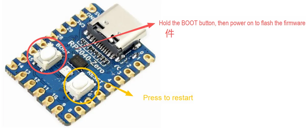
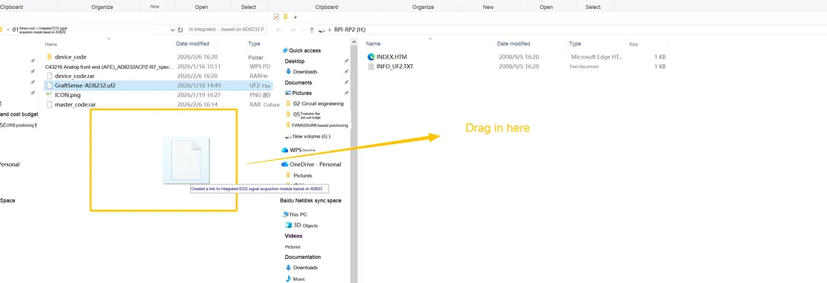
First press the BOOT button, a window will pop up on the computer, then drag the firmware below into it:
GraftSense-AD8232.uf2 913 KB
Then open the Thonny software, and download all the files in the Compressed Packet below to the main control board on the module:

Then press the RESET button, and the main control board on the module will start working. It is particularly noted that the first 3 seconds after power-on are reserved for filter initialization, during which no data will be output.
3.2.3 Lead Mode of ECG Module
The "lead configuration" for ECG acquisition refers to the method of capturing the potential difference formed by cardiac electrical activity on the body surface by attaching electrodes to specific positions on the human body. The module we developed adopts dual leads (differential acquisition) + reference electrode configuration, with the red, yellow and green electrodes having clear respective responsibilities to jointly achieve accurate ECG signal acquisition and interference suppression.
Here, we first need to insert the lead wires into the LEAD interface of the module, and then connect the lead patches to the electrode snaps:
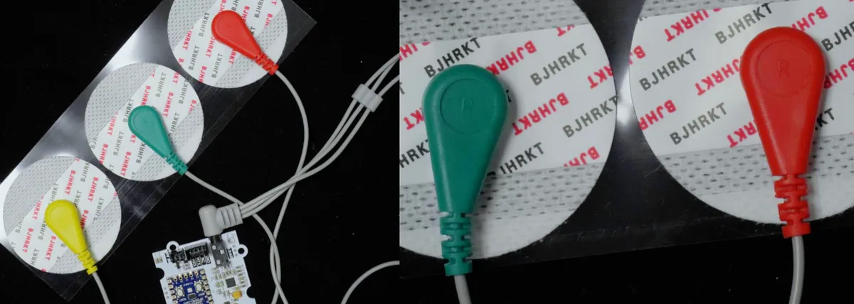
| Electrode color | Function | Recommended placement |
|---|---|---|
| Red (positive) | ECG signal positive input; captures positive potential changes of the heart's electrical activity | Upper right chest (below the clavicle) or inner right arm (e.g., above the right elbow) |
| Yellow (negative) | ECG signal negative input; forms a potential difference with the red electrode to extract the core ECG waveforms (e.g., P wave, QRS complex) | Upper left chest (below the clavicle, near the heart) or inner left arm (e.g., above the left elbow) |
| Green (reference electrode) | Ground electrode; eliminates common-mode interference on the body surface (e.g., power-line noise) and improves the signal-to-noise ratio | Lower right abdomen (below the right ribs) or inner right leg (e.g., above the right knee) |
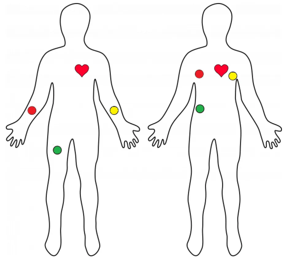
There are two common lead placement methods:
- Limb Lead Placement (Schematic Diagram of the Left Human Body) Red: Inner side of the right arm → Yellow: Inner side of the left arm → Green: Inner side of the right leg
- Mixed Chest Limb Taping Method (Schematic Diagram of the Right-Side Human Body) Red tape applied to the upper right chest → Yellow tape applied to the upper left chest → Green tape applied to the lower right abdomen
Also note that before applying the electrode pads:
- Before attaching the electrodes, wipe the skin with alcohol to remove oil and dead skin cells, ensure the electrodes fit closely against the skin, and reduce contact resistance.
- Electrode pads are disposable items; reusing them may easily lead to poor contact or infection.
- If unshielded lead wires are used, keep them away from electromagnetic interference sources such as power cords and computers to avoid signal distortion.
3.2.4 Description of Module Communication Protocol
Here, we adopt a fixed structure for the serial port to ensure communication reliability, and all frames conform to the following format:
| Field | Bytes | Value / Description | Notes |
|---|---|---|---|
| Frame header | 2 | 0xAA 0x55 | Fixed identifier used to distinguish valid data frames |
| Type | 1 | 0x01: command frame (host → module) 0x02: data frame (module → host) | Distinguishes frame direction and purpose |
| Length | 1 | Number of bytes in the following "Data" field (0~255) | Makes data parsing easier for the host |
| Data | N | Command content / data content (as defined by the protocol) | Variable length |
| Checksum | 1 | XOR of Type + Length + Data (low 8 bits) | Used to verify frame integrity |
| Frame tail | 2 | 0x0D 0x0A (carriage return + line feed) | Simplifies host parsing and debugging |
The format definition of its query/setting mode is as follows:
| Command code (hex) | Function type | Function description | Data length | Data format / value range | Notes |
|---|---|---|---|---|---|
| 0x01 | Query / Report | Raw ECG data | 2 bytes | 16-bit unsigned integer (0~65535, corresponding to −1V ~ 2V) | Both active reporting and passive query are supported |
| 0x02 | Query / Report | Filtered ECG data | 2 bytes | 16-bit unsigned integer (0~65535, corresponding to −1V ~ 2V) | Both active reporting and passive query are supported |
| 0x03 | Query / Report | Lead connection status | 1 byte | 0 = normal, 1 = lead off | Both active reporting and passive query are supported |
| 0x04 | Set (with response) | Set active reporting frequency | 1 byte | 50 / 100 / 125 (unit: Hz) | Passive setting only; returns a confirmation after setting |
| 0x05 | Set (with response) | Set active reporting mode | 1 byte | 0 = off, 1 = on | Passive setting only; returns a confirmation after setting |
| 0x06 | Set (with response) | Control AD8232 start/stop (working state) | 1 byte | 0 = stop, 1 = run | Passive setting only; returns a confirmation after setting |
| 0x07 | Query / Report | Module working status | 1 byte | 0 = stop, 1 = run | Both active reporting and passive query are supported |
| 0x08 | Query / Report | Heart rate value | 1 byte | 0~255 (unit: beats/min) | Both active reporting and passive query are supported |
In the active output mode, the module pushes a 5-byte combined data frame at the set frequency, and the format of the data segment is as follows:
| Byte position | Content | Description |
|---|---|---|
| 0 | Raw ECG data | 8-bit ADC value, high byte first; returns 0xFFFF in shutdown state |
| 1 | Filtered ECG data | 8-bit filtered value, high byte first; returns 0xFFFF in shutdown state |
| 2 | Lead-off detection status | 0x00 = normal, 0x01 = lead off |
| 3 | Module working status | 0x00 = working normally, 0x03 = shutdown |
| 4 | Heart rate value | Currently calculated heart rate value (unit: bpm, 0~255); returns 0xFFFF in shutdown state |
Here are some references (note that all are in hexadecimal format!!!):
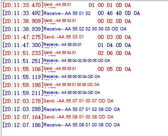
- Query raw ECG data (query commands only recognize the instruction code and ignore the data):
AA 55 01 01 00 01 0D 0A - Query the filtered ECG data (for query commands, only the instruction code is recognized, data is ignored):
AA 55 02 01 00 02 0D 0A - Query the disconnection detection status (for query commands, only the command code is recognized, data is ignored):
AA 55 03 01 00 03 0D 0A - Set active output mode:
AA 55 04 01 02 06 0D 0A - Set active output (0: Off, 1: On):
AA 55 05 01 00 05 0D 0A - Control AD8232 start/stop (0: off, 1: on):
AA 55 06 01 00 06 0D 0A - Query module working status (query-type instructions only recognize the command code and ignore data):
AA 55 07 01 00 07 0D 0A - Query heart rate value (query-type commands only recognize the instruction code and ignore the data):
AA 55 08 01 00 08 0D 0A
3.3 Application Experiment
Here, we use the GraftPort-RP2040 development board for testing, and the integrated ECG signal acquisition module based on the AD8232 uses the UART interface to communicate with the main controller.
Here, we first use the HY2.0-4P cable to connect the module to the GraftPort-RP2040 development board's UART1 interface. We use a polymer lithium battery and the GraftSense - SY7656-based lithium battery charge-discharge module to power the module, connect the lead wires and corresponding ECG electrodes as described above, and also need to connect the MiniUSB data cable to the UART interface on the underside of the main control board:
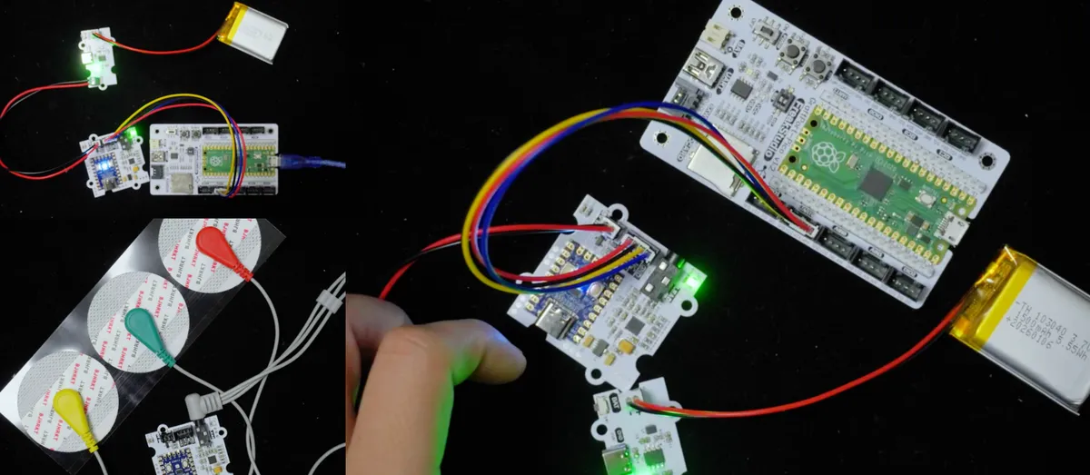
The module connections are shown in the following table:
development board pins | Module Pins | Description |
Pin 8 |
|
|
Pin 9 |
|
|
Here, we need to search for the relevant driver packages on uPyPI: https://upypi.net/zh/

Enter ad8232_driver to search, and the following will be displayed:

Click to copy the local installation command:
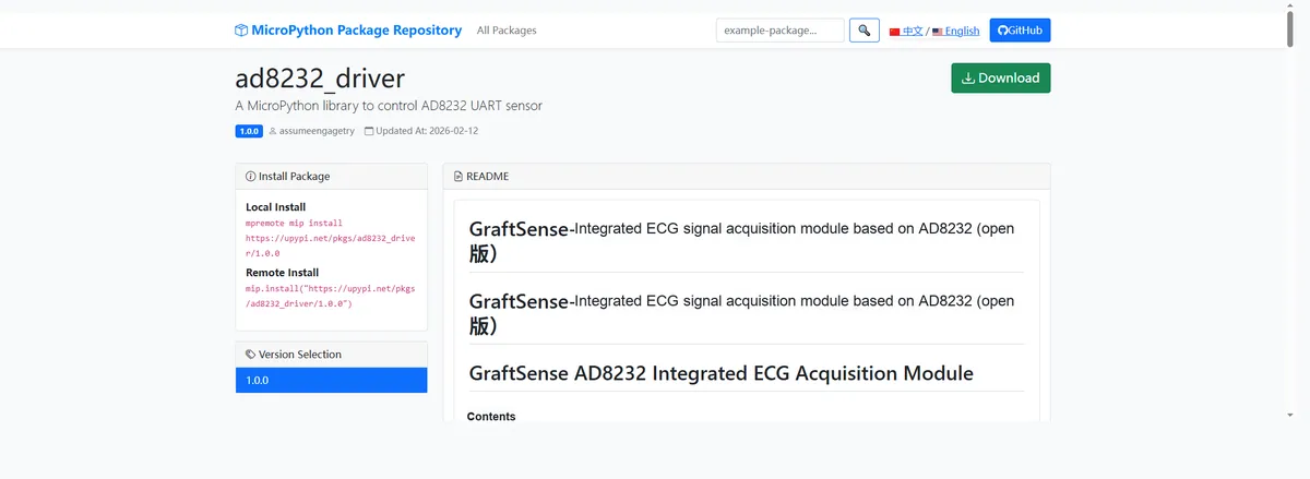
Here, we can import the module driver library code via the mip tool. The following are the usage commands for the mpremote tool:
mpremote mip install github:FreakStudioCN/GraftSense-Drivers-MicroPython/sensors/ad8232_driver
Import the integrated ECG signal acquisition module based on AD8232 - MicroPython driver code, then copy the following main.py code into our project:
# Python env   : MicroPython v1.23.0
# -*- coding: utf-8 -*-
# @Time    : 2026/1/19 PM 5:33
# @Author  : hogeiha
# @File    : main.py
# @Description : Usage example of the serial heart rate detection module

# ======================================== Import Modules =========================================

from machine import UART, Pin, Timer
import micropython
import time
from data_flow_processor import DataFlowProcessor
from ad8232_uart import AD8232_DataFlowProcessor

# ======================================== Global Variables ============================================

# ======================================== Functions ============================================

# ======================================== Custom Classes ============================================

# ======================================== Initialization configuration ===========================================

time.sleep(3)
print("FreakStudio: Serial Port Heart Rate Detection Module Usage Example")
# Module communication UART1
uart1 = UART(1, baudrate=115200, tx=Pin(8), rx=Pin(9))
# Waveform output UART0
uart = UART(0, baudrate=115200, tx=Pin(0), rx=Pin(1), bits=8, parity=None, stop=1)
# Data frame construction example
processordata = DataFlowProcessor(uart1)
# AD8232 serial module command send/parse example
ad8232 = AD8232_DataFlowProcessor(processordata)

# ========================================  Main Program  ============================================

# Start the ad8232
ad8232.control_ad8232_start_stop(True)
# Enable active reporting
ad8232.set_active_output(True)

while True:
    # Enable active reporting; the automatic timer parses and updates instance attributes
    raw_val_dc = ad8232.ecg_value
    filtered_val = ad8232.filtered_ecg_value

    # Active reporting does not include lead status; it must be queried and returned, and attributes are updated at the same time
    lead_status = ad8232.query_off_detection_status()
    heart_rate = ad8232.heart_rate

    # Output waveform information, view with the serial plotter
    uart_str = f"{raw_val_dc},{filtered_val}\r\n"
    uart.write(uart_str.encode('utf-8'))  # Explicit encoding to avoid truncation
    # Print heart rate and lead status to the terminal
    print(f"lead_status:{lead_status},heart_rate:{heart_rate}\r\n")
    time.sleep_ms(10)
The code above mainly performs the following tasks:
- Read the original ECG data and the filtered ECG data actively reported by the module;
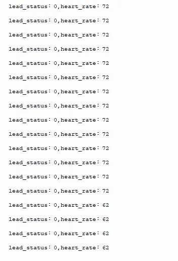
- Query the lead status of the active query module proactively (this information is not included in active reporting and requires manual query), and read the calculated heart rate value;
- Output raw/filtered ECG data via serial port 0 (in the format of
value1, value2\r\n) for a serial plotter to draw waveforms; - Print the lead status (whether it is detached) and the heart rate value in the terminal;
- It loops once every 10 milliseconds to ensure real-time data performance.
When flashing the code, the terminal outputs the following:
Next, we need to complete the configuration of SerialPlot the serial port plotter:
- Configure serial port parameters: On the
Porttab, select the correct serial port (e. g.COM4), set the baud rate to 115200, data bits to 8, stop bits to 1, and no parity bit - Click "Open" : After confirming the configuration is correct, click the "
Open" button in the upper right corner to open the serial port

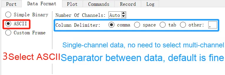
- Select the data format: switch to the
Data Formattab and select the "ASCII" format. In the case of single-channel data transmission, the comma is selected as the default data delimiter
As can be seen, the corresponding waveform is output:
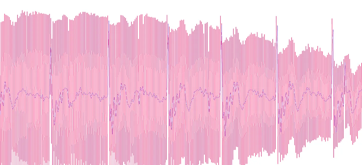
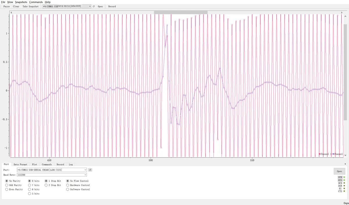
It can be observed that:
- Red original waveform: It contains obvious 50Hz power line interference (those dense high-frequency vertical lines) and baseline drift, which are common noises during ECG signal acquisition and will mask the real ECG features.
- Waveform after blue filtering: After the three-stage IIR digital filtering built into the module, power frequency interference and baseline drift are effectively suppressed, the waveform becomes smooth, and the P-QRS-T complex of the ECG signal can be clearly identified. In particular, the R-wave peak representing ventricular contraction is very prominent, which is the key basis for the subsequent heart rate calculation.
IV. Drivers
master_code.rar 13 KB
device_code.rar 7 KB
GraftSense-AD8232.uf2 913 KB
5. BOM & Recommended Alternative Parts
None.
VI. Revision History
Document Version | Date of Revision | Modifier | Modify Content |
v1.0 | 2026-01-29 | Zero High-Luck | Initialize the document |
v1.1 | 2026-02-12 | Xin Ruili | Create an open version of the document based on the internal document version v1.0. |
v1.2 | 2026-03-29 | Xin Ruili | Modified the application experiment section |
VII. Relevant Materials
7.1 Chip Datasheet
AD8232ACPZ-RL.pdf 849 KB
7.2 Unique Icons for PCB Silk Screen