Contents
- I. Module Introduction
- 2. Introduction to Main Chips
- 2.1 Chip Overview
- 2.2 Pin Definition
- 2.3 Functional Block Diagram
- 2.4 Performance Parameters
- 2.5 Reference Circuit
- 2.6 Chip Configuration
- 2.7 Communication Interfaces and Related Protocols
- 2.8 PCB Routing Precautions
- III. Instructions for Circuit Engineering and Module Usage
- 3.1 Circuit Source Engineering
- 3.2 Module Usage Instructions
- 3.3 Application Experiment
- 4. Drivers
- 5. BOM & Recommended Alternative Parts
- VI. Revision History
- VII. Relevant Materials
- 7.1 Chip Datasheet
- 7.2 Unique Icons for PCB Silk Screen
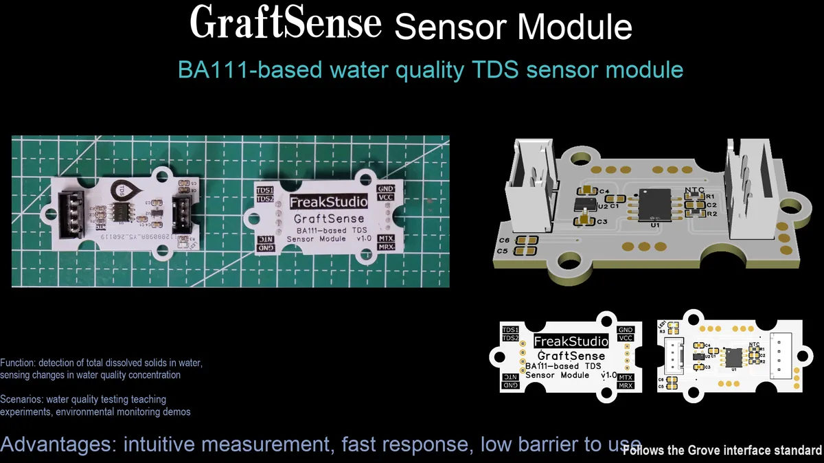
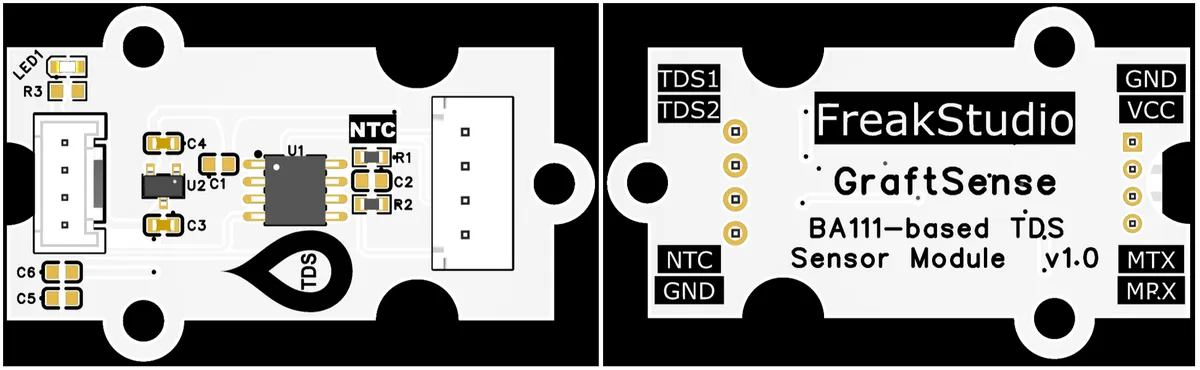
I. Module Introduction
BA111-based Water Quality TDS Sensor Module is a water quality detection module with the BA111 chip from Bitatom as its core, supporting the UART communication interface and capable of directly outputting calculated TDS (total dissolved solids) and temperature data; the module integrates a 5V-to-3.3V circuit, power filtering and a power indicator, operates at a supply voltage of 3.3V with a working current < 3mA, featuring low power consumption and stable power supply;Equipped with a communication interface and TDS electrode interface, it is applicable to scenarios such as household water purifiers, portable water quality testing pens, and aquarium water quality management systems, enabling convenient water quality monitoring.
2. Introduction to Main Chips
BA111 is a dedicated chip specialized in water quality testing. It integrates a high-precision oscillation circuit, an analog-to-digital conversion circuit, and a floating-point arithmetic unit. By adopting the patented conductivity-to- TDS conversion algorithm and temperature correction algorithm, it can rapidly detect the total dissolved solids (TDS) and water temperature of water samples, and perform automatic correction within a wide temperature range to reduce the impact of temperature on TDS measurement, making it suitable for water quality monitoring scenarios such as domestic water.
2.1 Chip Overview
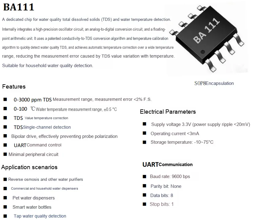
BA111 is a water quality testing chip packaged in SOP8 . It integrates high-precision oscillation, analog-to-digital conversion, and floating-point operation units. Through patented conductivity- TDS conversion algorithm and temperature correction algorithm, it can achieve TDS detection in the range of 0-3000ppm (error < 2%) and water temperature detection in the range of 0-100 ℃ (accuracy ± 0.5 ℃), and can automatically correct in a wide temperature range to reduce temperature errors.It features bipolar drive to prevent probe polarization, and adopts UART interface (9600bps) for communication. It only requires 3.3V power supply with an operating current of less than 3mA, boasts an extremely simple peripheral circuit design, and is widely applicable to water quality monitoring scenarios such as water purifiers, household/commercial water dispensers, and smart water cups.
2.2 Pin Definition
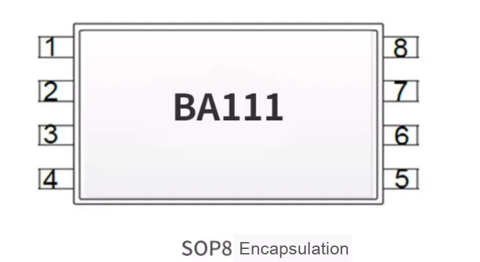
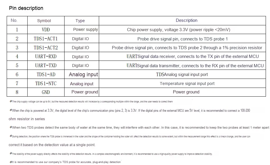
2.3 Functional Block Diagram
None.
2.4 Performance Parameters
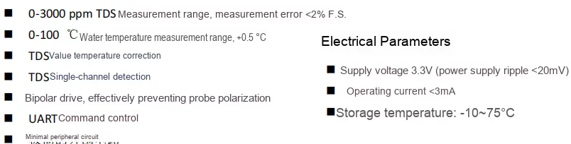
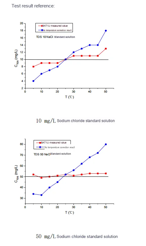
These two performance curves verify the effectiveness of the temperature correction function of the BA111 chip: in the tests with 10 mg/L and 50 mg/L sodium chloride standard solutions, the result without temperature correction (the blue curve) rises significantly as the temperature increases, reflecting that the direct impact of temperature on conductivity will lead to high TDS measurement values.Furthermore, the BA111 temperature-corrected measurement values (red curve) remain basically stable across the entire temperature range, always closely matching the theoretical values of the standard solution. This indicates that its temperature correction algorithm can effectively counteract the interference of temperature fluctuations, significantly reducing the measurement error of TDS and ensuring the accuracy and stability of the test results.
2.5 Reference Circuit
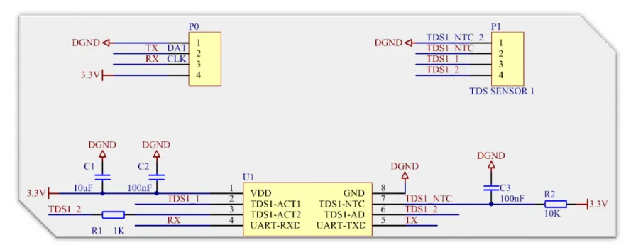
2.6 Chip Configuration
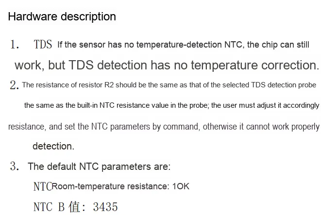
This module is of Plug and Play type, requiring no hardware configuration or software register setup.
2.7 Communication Interfaces and Related Protocols
2.8 PCB Routing Precautions
III. Instructions for Circuit Engineering and Module Usage
3.1 Circuit Source Engineering
To obtain the circuit source project, please follow the official account [Freak Embedded].
3.2 Module Usage Instructions
The schematic diagram of this module is shown below:
SCH_Water Quality TDS Sensor Module Based on BA111_v1.0.pdf 2.2 MB
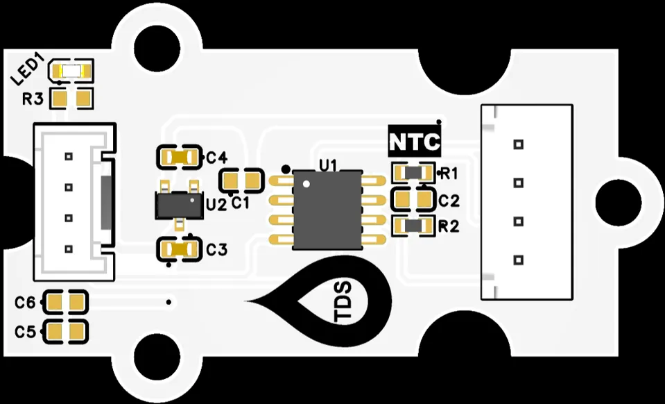
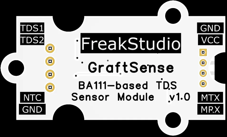
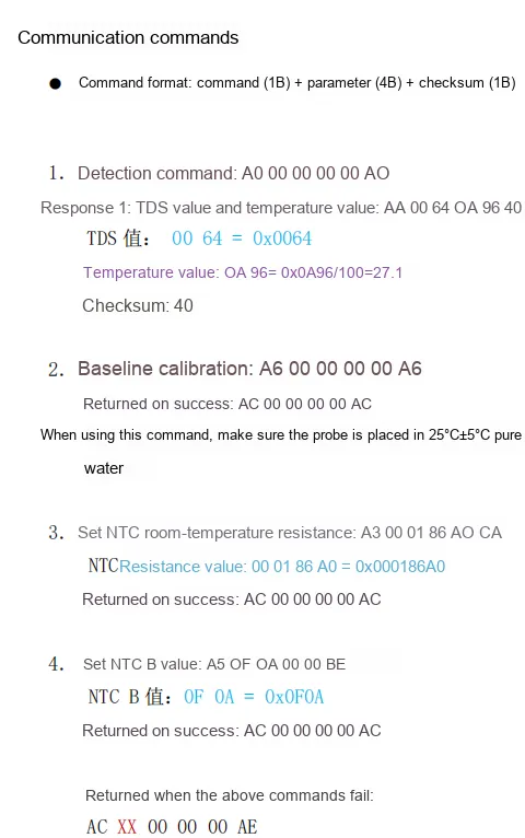
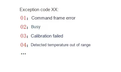
This module provides a serial port UART interface MRX and MTX: here M stands for master, meaning it is the MCU 's RX corresponding to the module' s TX;When in use, note that the communication parameters of the UART interface of the microcontroller must be consistent with those of the BA111 chip. The MCU can control the operation of the module by sending commands (such as calibration commands and sampling period configuration commands) to MRX, and the module will actively postback real-time MTX real-time TDS measurement values, NTC temperature values and check information, so that the system can quickly obtain water quality and temperature data. It is suitable for scenarios that require real-time water quality monitoring such as water purifiers and smart water cups.
When in use, we need to first insert the TDS electrode probe into the probe XH2.54-4P interface of the module:
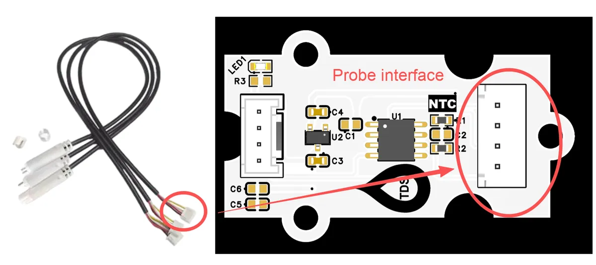
The pin definition is as follows: the black and red wires correspond to the TDS detection electrode, and the white and yellow wires correspond to the NTC temperature sensor.
Additionally, please note the following:
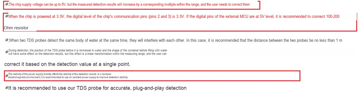
- Calibration Specification: For initial use or after long-term storage, baseline calibration must be performed. Before calibration, be sure to place the probe in pure water at 25℃±5℃ to ensure the accuracy of the detection reference.
- Probe Interference: If two TDS probes are used simultaneously to test the same water body, the distance between the two probes shall be kept at more than 1 meter to avoid signal interference between the electrodes.
- Environmental impact: The depth to which the probe is immersed in water and the shape of the container have a linear effect on the detection results, and the data can be corrected independently based on the detection values of known calibration points.
- Maintenance Recommendations: After prolonged use, regularly check whether scale has formed on the surface of the probe electrode, and clean it in a timely manner to maintain detection accuracy; when plugging or unplugging the probe, ensure the plug is firmly inserted to avoid abnormal data caused by poor contact.
3.3 Application Experiment
Here, we use the GraftPort-RP2040 development board for testing, and connect the BA111-based water quality TDS sensor module to communicate with the main controller via the UART interface.
Here, we first use the HY2.0-4P cable to connect the module to the GraftPort-RP2040 development board's UART0 interface, and connect the TDS probe to the module at the same time:
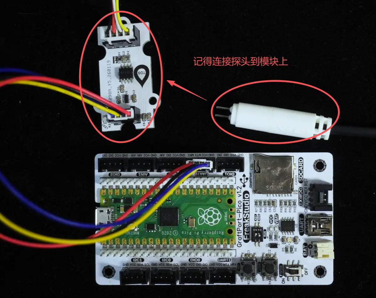
The module connections are shown in the following table:
Development Board Pins | Module Pins | Description |
Pin 16 |
|
|
Pin 17 |
|
|
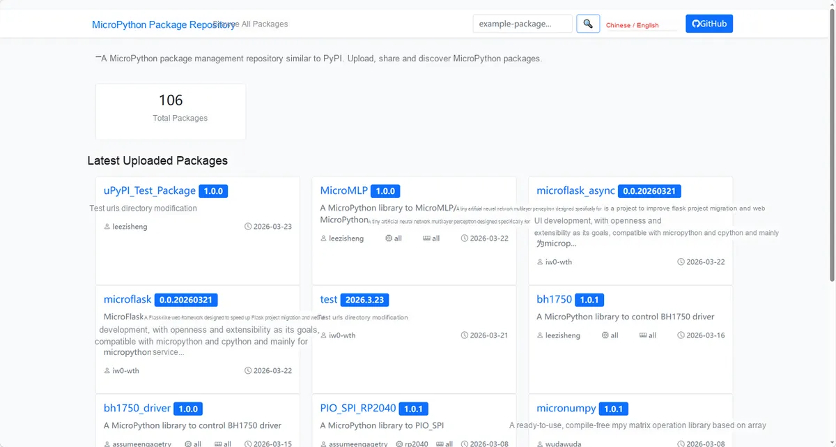
Here, we need to search for the relevant driver packages on uPyPI: https://upypi.net/zh/
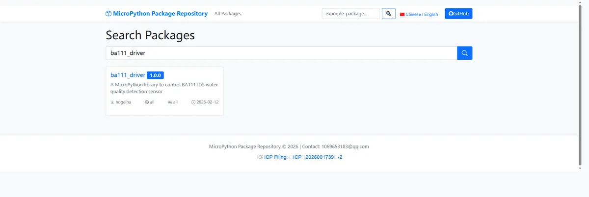
Enter ba111_driver to search, and the following will be displayed:
Click to copy the local installation command:
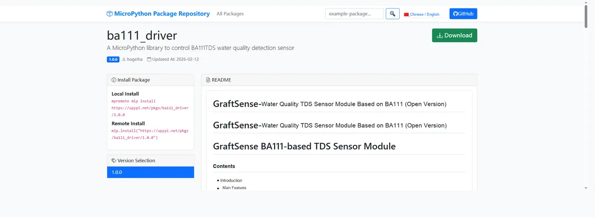
Here, we can import the module driver library code via the mip tool. The following are the usage commands for the mpremote tool:
mpremote mip install github:FreakStudioCN/GraftSense-Drivers-MicroPython/sensors/ba111_driverImport the MicroPython driver code for the BA111-based water quality TDS sensor, then copy the following main.py code into our project:
# Python env   : MicroPython v1.26.1
# -*- coding: utf-8 -*-
# @Time    : 2026/1/19 PM 5:33
# @Author  : hogeiha
# @File    : main.py
# @Description : Test code for ba111_tds water quality detection

# ======================================== Import Modules =========================================

from ba111_tds import BA111TDS
import time
from machine import Pin, UART

# ======================================== Global Variables ============================================

# ======================================== Functions ============================================

# ======================================== Custom Classes ============================================

# ======================================== Initialization configuration ===========================================

time.sleep(3)
print("FreakStudio: test Light Intensity Sensor now")

uart = UART(0, baudrate=9600, bits=8, parity=None, stop=1, tx=Pin(16), rx=Pin(17))
sensor = BA111TDS(uart)

# Set parameters (if needed)
sensor.set_ntc_resistance(10000)
sensor.set_ntc_b_value(3950)

# ========================================  Main Program  ============================================

input("Place the baseline calibration probe into pure water at 25°C - 5°C, and press any key to calibrate.")
# Calibrate
if sensor.calibrate():
    print("Calibration successful")
    while True:
        # Read data
        result = sensor.detect()
        if result:
            tds, temp = result
            print(f"TDS: {tds}ppm, temp: {temp}℃")
            time.sleep(1)
else:
    print("Calibration failed")
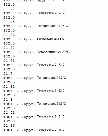
After burning the code, when the following prompt appears in the terminal, press any key. Meanwhile, note that when using the calibration command, ensure that the probe is placed in pure water at 25°C ± 5°C:

4. Drivers
ba111_driver.rar 6 KB
5. BOM & Recommended Alternative Parts
None.
VI. Revision History
Document Version | Date of Modification | Modifier | Revised Content |
v1.0 | 2026-01-29 | Zero Kōkō | Initialize Document |
v1.1 | 2026-02-12 | Xin Ruili | Create an open version of the document based on the internal document version v1.0. |
v1.2 | 2026-03-29 | Xin Ruili | Modified the application experiment section |
VII. Relevant Materials
7.1 Chip Datasheet
BA111-V1.1.pdf 927 KB
7.2 Unique Icons for PCB Silk Screen