Contents
- I. Module Introduction
- 2. Introduction to Main Chips
- 2.1 Chip Overview
- 2.2 Pin Definition
- 2.3 Functional Block Diagram
- 2.4 Performance Parameters
- 2.5 Reference Circuit
- 2.6 Chip Configuration
- 2.7 Communication Interfaces and Related Protocols
- 2.8 PCB Routing Precautions
- III. Instructions for Circuit Engineering and Module Usage
- 3.1 Circuit Source Engineering
- 3.2 Module Usage Instructions
- 3.3 Application Experiment
- 4. Drivers
- 5. BOM & Recommended Alternative Parts
- VI. Revision History
- VII. Relevant Materials
- 7.1 Chip Datasheet
- 7.2 Unique Icons for PCB Silk Screen
I. Module Introduction
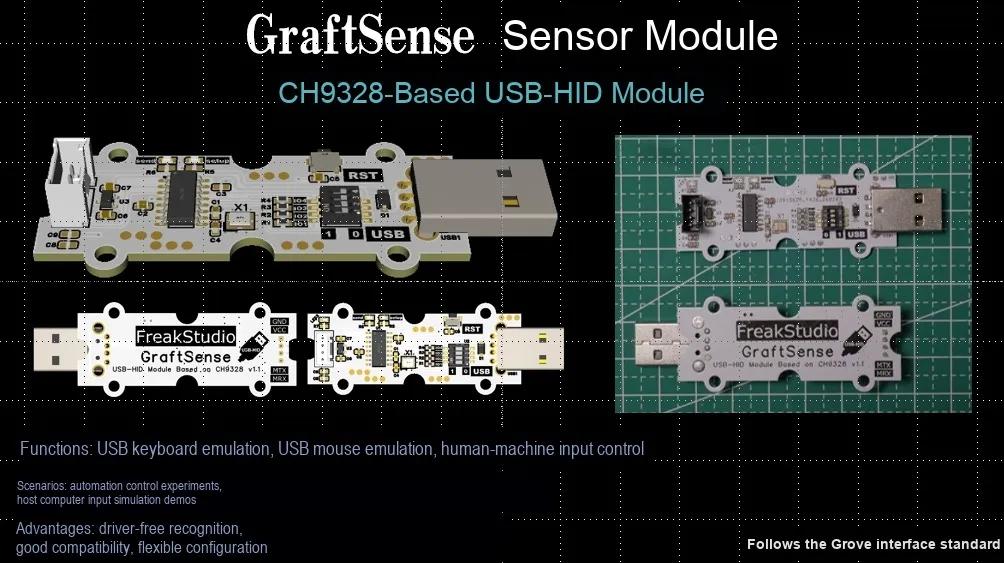
The USB-HID module based on CH9328 is a serial port-to- HID keyboard module with CH9328 chip as the core, supporting one-way data transmission, and can receive data such as ASCII codes sent by serial port UART , and pack them into standard keyboard code values according to the HID keyboard specification, and upload them to the computer through the USB port. The function of simulating keyboard input of serial port devices can be realized without programming;This module integrates an address selection circuit, a reset button, a 5V-to-3.3V conversion circuit, power filtering, and multi-status indicators, and supports 12Mbps full-speed USB 2.0 transmission. Its default serial port transmission rate is 9600bps, which is suitable for scenarios such as analog keyboard input for microcontroller/embedded systems, remote keyboard control of IoT devices, data-to-keyboard entry conversion for serial port devices, and manual keyboard operation simulation for automated test systems.
2. Introduction to Main Chips
CH9328 is a dedicated serial-to- HID keyboard chip launched by Qinheng. Adopting the SOP16 package and supporting 3.3V/5V dual power supply, it can convert serial port data into standard keyboard codes and upload them via USB 2.0 full-speed without programming. It supports customizable VID / PID with extremely simple peripheral circuits, enabling keyboard simulation functions for embedded devices.
2.1 Chip Overview
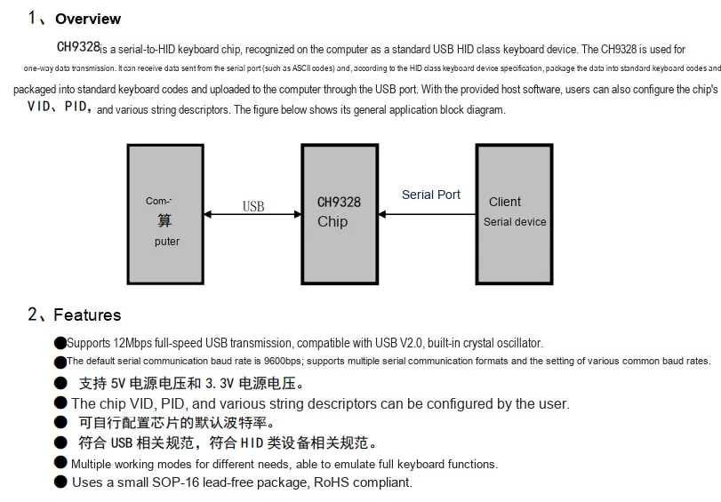
CH9328 is a dedicated chip for serial port to HID keyboard, which will be recognized as a standard USB HID class device on a computer. It can receive data such as ASCII codes sent by serial port devices via unidirectional data transmission, package the data into standard keyboard code values in accordance with the HID specification, and upload them to the computer via USB 2.0 full-speed (12Mbps) ;It defaults to a serial port baud rate of 9600bps, supports multiple configurations, is compatible with 3.3V/5V dual power supply, and also allows customization via host computer software VID, PID and string descriptors. It features multiple operating modes to simulate full keyboard functions, adopts the compact SOP-16 lead-free package, and is suitable for various embedded scenarios requiring simulated keyboard input.
2.2 Pin Definition
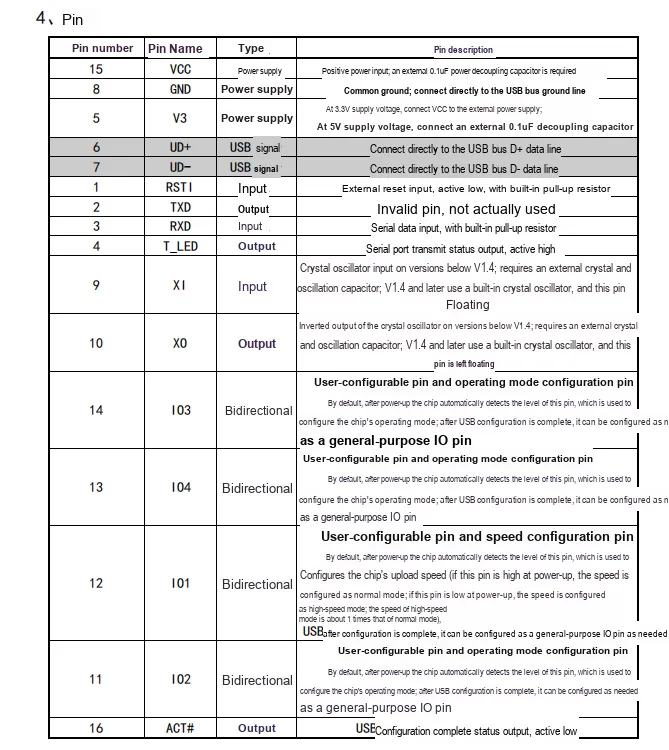
2.3 Functional Block Diagram
None.
2.4 Performance Parameters
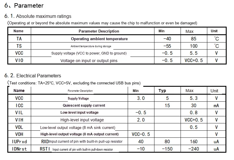
CH9328 has performance parameters consisting of two parts: in terms of absolute maximum ratings, the operating temperature ranges from -40℃ to 85℃, the storage temperature ranges from -55℃ to 100℃, and the power supply voltage limit ranges from -0.5V to 5.5V; under the test conditions of 25℃ and 5V power supply, its electrical parameters show that the adaptable power supply voltage is 3.0~5.3V (typical value 5V), the typical quiescent current is 15mA (maximum 30mA), meanwhile the input and output levels conform to conventional logic, and some pins have built-in pull-up resistors.
2.5 Reference Circuit
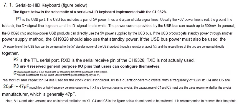

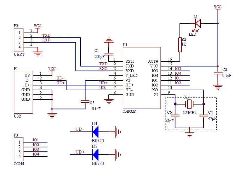
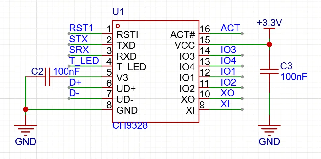
CH9328 The application circuit takes the chip as the core, receives external serial port data via the P2 interface's UART, and outputs standard USB standard HID keyboard signals through the P1 interface after processing. It is equipped with a 12MHz crystal oscillator and decoupling capacitors to ensure clock and power supply stability; the ACT# pin is connected to a status indicator light, while extended IO interfaces are also drawn out, and diodes are connected in series on the USB differential lines for protection. With a compact overall design, it can quickly implement the function of converting serial port to HID keyboard.
2.6 Chip Configuration
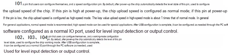
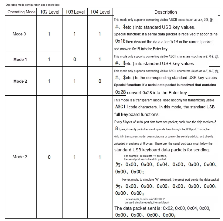
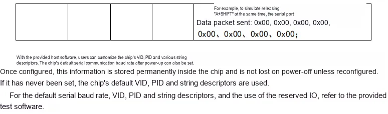
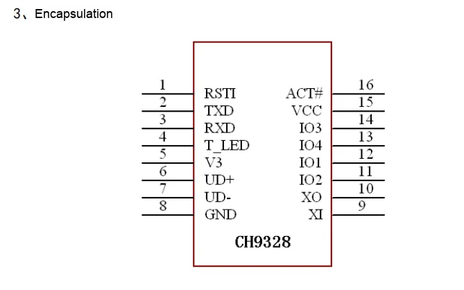
CH9328 features a flexible configuration method that supports dual settings via hardware pins and host computer software: in terms of hardware, I01 pin's level at power-on can configure the upload speed (high level for normal mode, low level for high-speed mode which is 1 time the speed of normal mode), IO2, IO3, IO4 pin level combinations can select 4 operating modes, among which modes 0-2 support converting visible ASCII codes to USB key values with some special conversion functions, and mode 3 is a pass-through mode that enables full keyboard functions;All configuration pins, after USB configuration is completed, can be set as general-purpose PC via software to function as regular IO pins for level detection or output; in terms of software, users can also customize VID, PID, string descriptors and default serial baud rate through the host computer, and the configuration information will not be lost after power off.
2.7 Communication Interfaces and Related Protocols
None.
2.8 PCB Routing Precautions
None.
III. Instructions for Circuit Engineering and Module Usage
3.1 Circuit Source Engineering
To obtain the circuit source project, please follow the official account [Freak Embedded].
3.2 Module Usage Instructions
The schematic diagram of this module is shown below:
SCH_CH9328-Based USB-HID Module-v1.0.pdf 2.7 MB
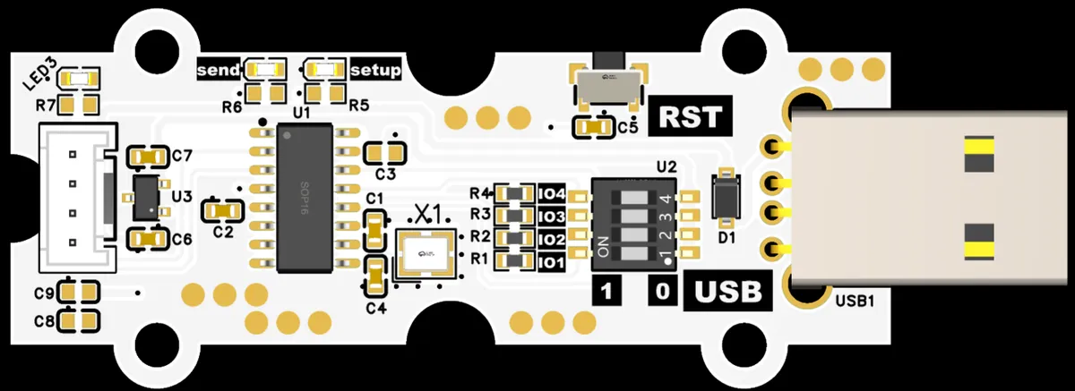
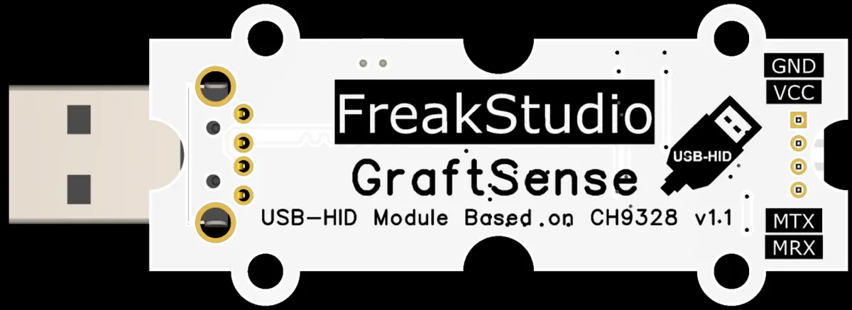
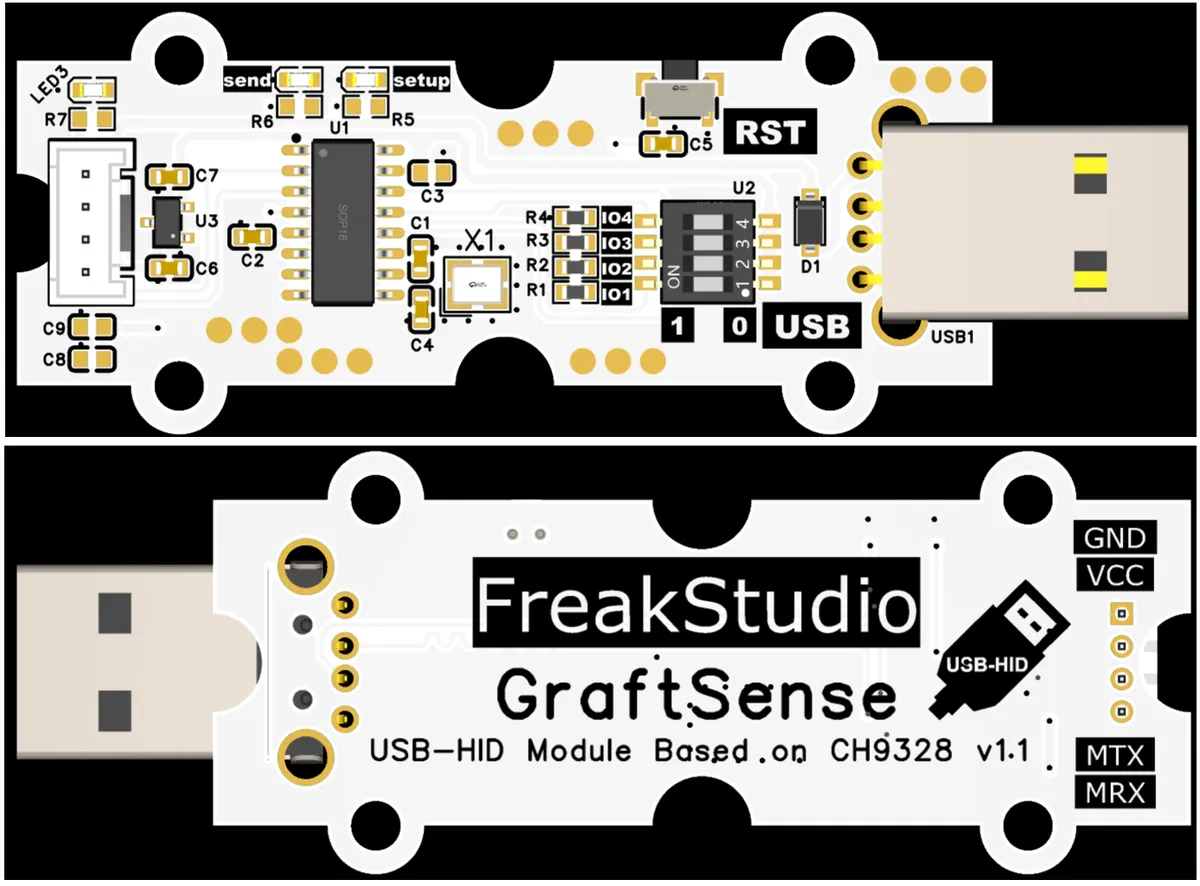
This module provides a serial port UART interface MRX and MTX: where M stands for master, meaning the MCU 's RX corresponds to the module' s TX, which is used to connect to the microcontroller's UART interface. The core of this module communicates with the host computer via the USB interface, and interacts with external devices through serial port pins at the same time. After the module is powered on, CH9328 will automatically detect the IO pin level (determined by the DIP switch status of the address selection circuit U2) to complete the initialization of parameters such as working mode and communication speed;After that, it can be recognized by the host as a USB-HID device, realizing transparent transmission between serial port data and the USB-HID protocol. The power indicator and status indicator will visually display the power supply and communication status of the module.
Address selection circuit U2 is a 4-bit DIP switch, which is directly connected to the IO1, IO2, IO3, and IO4 pins of the CH9328. The ON / OFF status of the DIP switch corresponds to the high/low level of the pins:
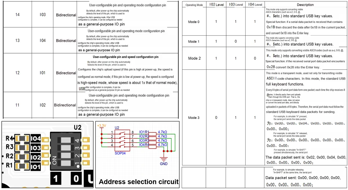
It can be clearly seen from the schematic diagram that:
- DIP switch
U2pins 1,2, 3, and 4 are directly connected to+ 3.3V; - Pins 5,6, 7 and 8 are respectively connected to
GNDvia 4.7kΩ resistors, and simultaneously serve asIO1R1,IO2R2,IO3R3,IO4R4to output toCH9328.
Therefore, the level logic is as follows:
- When the DIP switch is toggled to
ON, the corresponding switch contact closes, and theIOpin is directly connected to + 3.3V, corresponding to a high level (1). - When the DIP switch is toggled to
OFF, the corresponding switch contact opens, and theIOpin is pulled down toGNDvia a resistor, corresponding to a low level (0).
Correspondence table between DIP switches and working modes:
| Working mode | IO2 (DIP switch 2) | IO3 (DIP 3) | IO4 (DIP 4) | DIP switch status |
|---|---|---|---|---|
| Mode 0 | 1 (ON) | 1 (ON) | 1 (ON) | 2-ON, 3-ON, 4-ON |
| Mode 1 | 1 (ON) | 0 (OFF) | 1 (ON) | 2-ON, 3-OFF, 4-ON |
| Mode 2 | 1 (ON) | 1 (ON) | 0 (OFF) | 2-ON, 3-ON, 4-OFF |
| Mode 3 | 0 (OFF) | 1 (ON) | 1 (ON) | 2-OFF, 3-ON, 4-ON |
| Speed mode | IO1 (DIP 1) | DIP switch status |
|---|---|---|
| Normal mode | 1 (ON) | 1-ON |
| High-speed mode | 0 (OFF) | 1-OFF |
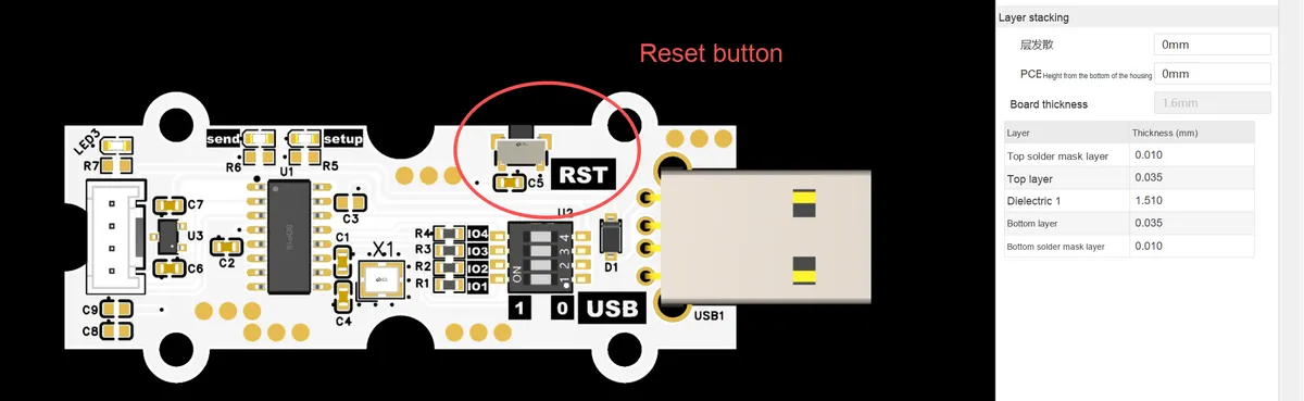
On the module, the RST reset button is designed to quickly activate the modified U2 DIP switch configuration: after you adjust the DIP switches to switch the working mode or communication speed, there is no need to unplug and replug the USB interface. Simply press the RST button to trigger the reset of the CH9328 chip, which will re-detect the IO pin levels and load the new configuration, making the new mode or speed settings take effect immediately, greatly improving the convenience of debugging and usage.
3.3 Application Experiment
Here, we use the GraftPort-RP2040 development board for testing, and the USB-HID module based on CH9328 uses the UART interface to communicate with the main controller.
Here, we first use the HY2.0-4P cable to connect the module to the GraftPort-RP2040 development board's UART0 interface:
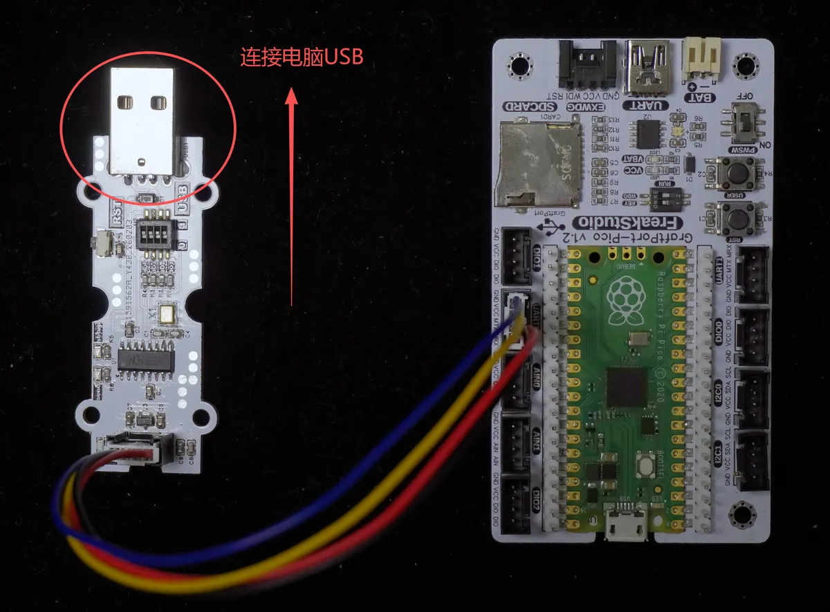
Then insert the module into the USB port on the computer, and note that you need to configure its working mode and rate first in accordance with the content in Section 3.2 Module Usage Instructions.
The module connections are shown in the following table:
Development Board Pins | Module Pins | Description |
Pin 16 |
|
|
Pin 17 |
|
|
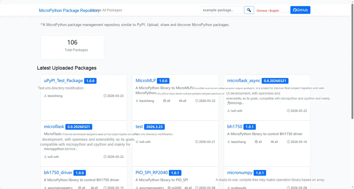
Here, we need to search for the relevant driver packages on uPyPI: https://upypi.net/zh/
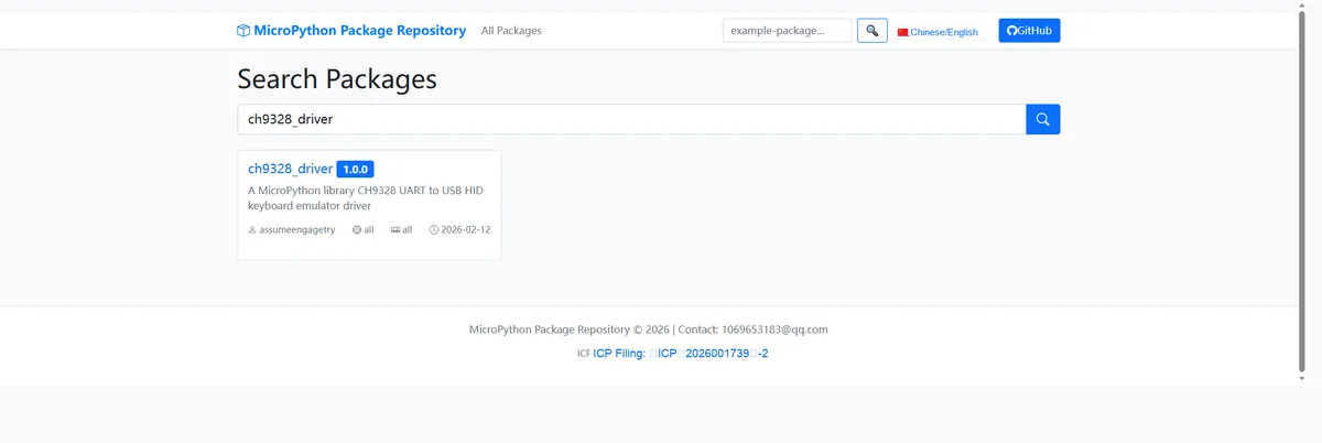
Enter ch9328_driver to search, and the following will be displayed:
Click to copy the local installation command:
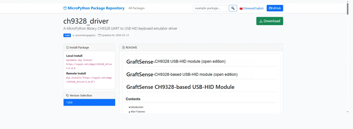
Here, we can import the module driver library code via the mip tool. Below are the usage commands for the mpremote tool:
mpremote mip install github:FreakStudioCN/GraftSense-Drivers-MicroPython/input/ch9328_driverAfter importing the USB-HID module based on CH9328 - MicroPython driver code, copy the following main.py code into our project:
# Python env   : MicroPython v1.23.0
# -*- coding: utf-8 -*-
# @Time    : 2026/1/19 PM 5:33
# @Author  : hogeiha
# @File    : main.py
# @Description : CH9328 test example

# ======================================== Import Modules =========================================

import time
from machine import UART, Pin
from ch9328 import CH9328

# ======================================== Global Variables ============================================

# Change according to hardware configuration
mode = 3

# ======================================== Functions ============================================

def test_mode0():
    """
    Test the Mode0 operating mode of the CH9328.

    Function verification:
    - Set the keyboard to Mode0
    - Send the string "Hello"
    - Send a carriage return/line feed (CR/LF)
    - Send the string "Mode0"

    Mode0 features:
    - Supports converting visible ASCII characters to standard USB key values
    - Special handling: when 0x1B (ESC) is received, the data after 0x1B in the current packet is discarded, and 0x1B is converted to the Enter key
    - Use the crlf() method to send 0x1B to implement the Enter function

    Note:
        - Mode0 is suitable for sending ASCII characters where an Enter function is needed
        - The Enter function is implemented through 0x1B escaping

    ==========================================

    Test CH9328 Mode0 working mode.

    Function verification:
    - Set keyboard to Mode0 mode
    - Send string "Hello"
    - Send carriage return/line feed (CR/LF)
    - Send string "Mode0"

    Mode0 features:
    - Supports visible ASCII characters conversion to standard USB key values
    - Special handling: When receiving 0x1B (ESC), discards data after 0x1B in current packet, and converts 0x1B to Enter key
    - Uses crlf() method to send 0x1B for Enter function

    Note:
        - Mode0 is suitable for ASCII character transmission scenarios requiring Enter function
        - Enter function is implemented through 0x1B escape
    """
    key.set_keyboard_mode(0)
    key.send_string("Hello")
    key.crlf()
    key.send_string("Mode0")

def test_mode1():
    """
    Test the Mode1 operating mode of the CH9328.

    Function verification:
    - Set the keyboard to Mode1
    - Send the string "Hello"
    - Send the string "Mode1"

    Mode1 features:
    - Only supports converting characters corresponding to visible ASCII codes (such as a-z, 0-9, @, #, $, etc.) to standard USB key values
    - No special character escape function
    - The simplest ASCII sending mode

    Note:
        - Mode1 is suitable for pure ASCII character input where no Enter function is needed
        - Special control character escaping is not supported

    ==========================================

    Test CH9328 Mode1 working mode.

    Function verification:
    - Set keyboard to Mode1 mode
    - Send string "Hello"
    - Send string "Mode1"

    Mode1 features:
    - Only supports converting visible ASCII codes (e.g., a-z, 0-9, @, #, $, etc.) to standard USB key values
    - No special character escape function
    - Simplest ASCII transmission mode

    Note:
        - Mode1 is suitable for pure ASCII character input without Enter function requirement
        - Does not support special control character escape
    """
    key.set_keyboard_mode(1)
    key.send_string("Hello")
    key.send_string("Mode1")

def test_mode2():
    """
    Test the Mode2 operating mode of the CH9328.

    Function verification:
    - Set the keyboard to Mode2
    - Send the string "Hello"
    - Send a carriage return/line feed (CR/LF)
    - Send the string "Mode2"

    Mode2 features:
    - Supports converting visible ASCII characters to standard USB key values
    - Special function: if 0x28 is encountered in a received serial data packet, 0x28 is converted to the Enter key
    - Use the crlf() method to send 0x28 to implement the Enter function

    Note:
        - Mode2 is similar to Mode0, but uses a different Enter escape character (0x28 vs 0x1B)
        - Suitable for scenarios that need an Enter function and where 0x1B may be used as a normal character

    ==========================================

    Test CH9328 Mode2 working mode.

    Function verification:
    - Set keyboard to Mode2 mode
    - Send string "Hello"
    - Send carriage return/line feed (CR/LF)
    - Send string "Mode2"

    Mode2 features:
    - Supports visible ASCII characters conversion to standard USB key values
    - Special function: When receiving 0x28 in serial data packet, converts 0x28 to Enter key
    - Uses crlf() method to send 0x28 for Enter function

    Note:
        - Mode2 is similar to Mode0 but uses different Enter escape character (0x28 vs 0x1B)
        - Suitable for scenarios requiring Enter function where 0x1B might be used as normal character
    """
    key.set_keyboard_mode(2)
    key.send_string("Hello")
    key.crlf()
    key.send_string("Mode2")

def test_mode3():
    """
    Test the Mode3 (transparent transmission) operating mode of the CH9328.

    Function verification:
    1. Set the keyboard to Mode3
    2. Create a list of all modifier keys
    3. Delay 3 seconds for preparation
    4. Click all normal keys in turn (HID codes 0x04~0x65)
    5. Click all modifier keys in turn

    Mode3 features:
    - Transparent transmission mode, supports sending 8-byte HID data packets directly
    - Supports full HID keyboard functionality, including modifier keys
    - Provides the most flexible keyboard simulation control

    Test content:
    - Iterate through and test all normal keys (letters, digits, function keys, etc.)
    - Iterate through and test all modifier keys (Ctrl, Shift, Alt, Win, etc.)
    - 50ms interval between each key operation

    Note:
        - Mode3 requires manually constructing HID data packets
        - Suitable for scenarios that need fine control of keyboard operations
        - There is a 3-second delay before the test to make sure the user switches to the target window

    ==========================================

    Test CH9328 Mode3 (passthrough) working mode.

    Function verification:
    1. Set keyboard to Mode3 mode
    2. Create list of all modifier keys
    3. Delay 3 seconds for preparation
    4. Cycle through clicking all normal keys (HID codes 0x04~0x65)
    5. Cycle through clicking all modifier keys

    Mode3 features:
    - Passthrough mode, supports direct transmission of 8-byte HID data packets
    - Supports complete HID keyboard functions, including modifier keys
    - Provides most flexible keyboard emulation control

    Test content:
    - Traverse and test all normal keys (letters, numbers, function keys, etc.)
    - Traverse and test all modifier keys (Ctrl, Shift, Alt, Win, etc.)
    - Each key operation interval is 50ms

    Note:
        - Mode3 requires manual construction of HID data packets
        - Suitable for scenarios requiring fine-grained keyboard control
        - 3-second delay before test ensures user switches to target window
    """
    key.set_keyboard_mode(3)
    # Create a dictionary of all modifier keys for easy scanning
    modifier = [
        CH9328.MODIFIER_LEFT_CTRL,
        CH9328.MODIFIER_LEFT_SHIFT,
        CH9328.MODIFIER_LEFT_ALT,
        CH9328.MODIFIER_LEFT_GUI,
        CH9328.MODIFIER_RIGHT_CTRL,
        CH9328.MODIFIER_RIGHT_SHIFT,
        CH9328.MODIFIER_RIGHT_ALT,
        CH9328.MODIFIER_RIGHT_GUI
    ]
    time.sleep(3)
    # Click all normal keys in turn
    for key_code in range(0x04, 0x66):
        key.tap_key(key_code)
        time.sleep_ms(50)
    # Click modifier keys in turn
    for i in range(8):
        key.tap_key(key_code=CH9328.KEY_NONE,modifier=modifier[i])
        time.sleep_ms(50)

# ======================================== Custom Classes ============================================

# ======================================== Initialization configuration ===========================================

time.sleep(3)
print("FreakStudio: CH9328 mode test example")

# Create a serial port instance
uart = UART(0, baudrate=9600, tx=Pin(16), rx=Pin(17))
# Create a CH9328 instance
key = CH9328(uart)

# ========================================  Main Program  ============================================

# Run the example according to the mode setting
if mode == 0:
    print("Testing Mode 0...")
    test_mode0()
elif mode == 1:
    print("Testing Mode 1...")
    test_mode1()
elif mode == 2:
    print("Testing Mode 2...")
    test_mode2()
elif mode == 3:
    print("Testing Mode 3...")
    test_mode3()
Here, we can manually adjust the variables according to the mode settings:
# Change according to hardware configuration
mode = 3
In the above code, we have performed the following operations:
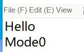
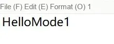
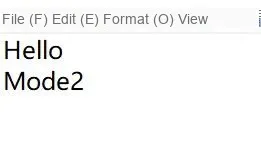
Mode0: Test sending theESC(0x1B) escape carriage return inASCIIformat, send "Hello" + carriage return + "Mode0"(0x1Bwill be converted to the Enter key, and the data following it will be discarded);Mode1: Test pure visibleASCIIcharacter transmission (without any special escaping), only send "HelloMode1";Mode2: Test0x28to send escaped carriage return viaASCII, send "Hello" + carriage return + "Mode2"(0x28will be converted to the carriage return key);Mode 3(Pass-through Mode): Test fullHIDkeyboard control. First delay for 3 seconds, then traverse and click all normal keys (HIDcodes0x04~0x65) and modifier keys (Ctrl/Shift/Alt/Win, etc.), with a 50ms interval between each key operation.
Burn the code, open the terminal, and the phenomenon is as follows:
mode2 's 0x1B is replaced with a line break:
mode1 No line breaks:
Mode2 's 0x28 is replaced with a newline:
Before Test Mode 3, we need to install the keyboard testing software on the target computer:
keyboardtestutility.exe 1.9 MB
mode3 Trigger all the keys in sequence:
USB-HID test mode 3.mp4 14.2 MB
4. Drivers
ch9328_driver.rar 10 KB
5. BOM & Recommended Alternative Parts
None.
VI. Revision History
Document Version | Date of Modification | Modifier | Revised Content |
v1.0 | 2026-01-29 | Zero Kōkō | Initialize Document |
v1.1 | 2026-02-12 | Xin Ruili | Create an open version of the document based on the internal document version v1.0. |
v1.2 | 2026-03-29 | Xin Ruili | Modified the application experiment section. |
VII. Relevant Materials
7.1 Chip Datasheet
Host computer software:
CH9328EVT.ZIP 93 KB
Keyboard Testing Software:
keyboardtestutility.exe 1.9 MB
CH9328.pdf 217 KB
7.2 Unique Icons for PCB Silk Screen