Contents
- I. Module Introduction
- 2. Introduction to Main Chips
- 2.1 Chip Overview
- 2.2 Pin Definition
- 2.3 Functional Block Diagram
- 2.4 Performance Parameters
- 2.5 Reference Circuit
- 2.6 Chip Configuration
- 2.7 Communication Interfaces and Related Protocols
- 2.8 PCB Routing Precautions
- III. Instructions for Circuit Engineering and Module Usage
- 3.1 Circuit Source Engineering
- 3.2 Module Usage Instructions
- 3.3 Application Experiment
- 4. Drivers
- 5. BOM & Recommended Alternative Parts
- VI. Revision History
- VII. Relevant Materials
- 7.1 Chip Datasheet
- 7.2 Unique Icons for PCB Silk Screen
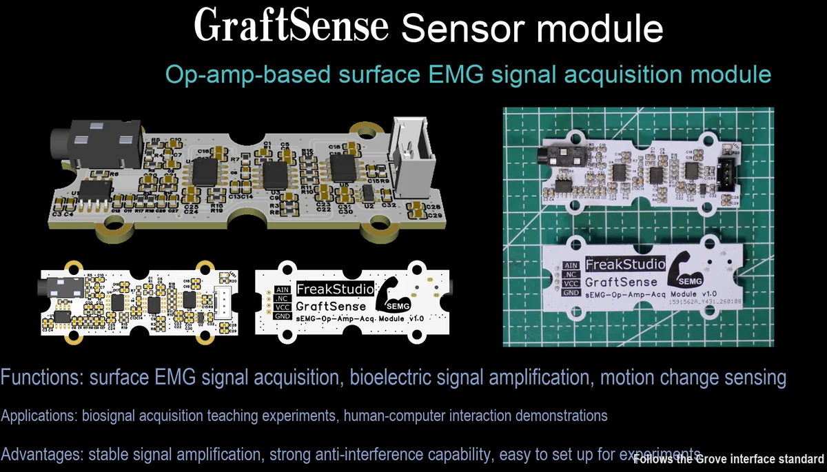
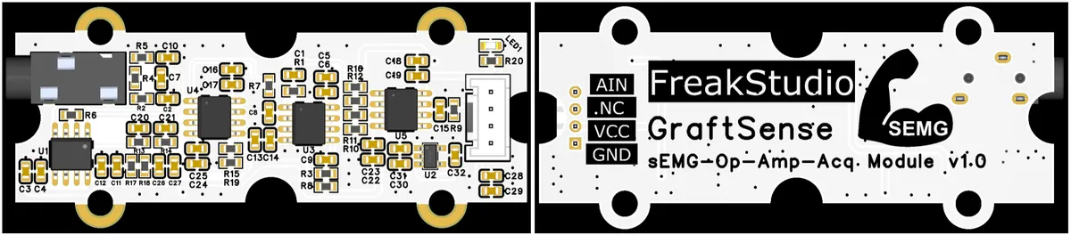
I. Module Introduction
Surface electromyogram signal operational amplifier-based acquisition module is a simple sEMG acquisition device designed for entry-level developers and enthusiasts. Built with discrete operational amplifier circuits, it integrates input buffering, multi-stage amplification and filtering links, enabling the acquisition and preprocessing of surface electromyogram signals. This module can effectively distinguish between the two states of "muscle activation" and "rest", meeting the basic needs of novice users to detect the presence or absence of muscle movement, and is suitable for non-professional scenarios such as fun interactive projects and teaching demonstrations.However, limited by the design of discrete circuits, its signal anti-interference capability and acquisition accuracy are relatively limited, making it unable to support professional applications such as EMG signal spectrum analysis and amplitude quantization, and it is more suitable as a low-cost entry-level tool for exploring myoelectric interaction.
2. Introduction to Main Chips
2.1 Chip Overview
None.
2.2 Pin Definition
None.
2.3 Functional Block Diagram
None.
2.4 Performance Parameters
None.
2.5 Reference Circuit
None.
2.6 Chip Configuration
None.
2.7 Communication Interfaces and Related Protocols
None.
2.8 PCB Routing Precautions
None.
III. Instructions for Circuit Engineering and Module Usage
3.1 Circuit Source Engineering
To obtain the circuit source project, please follow the official account [Freak Embedded].
3.2 Module Usage Instructions
The schematic diagram of this module is shown below:
SCH_Surface EMG Signal Op-Amp Acquisition Module_v1.1.pdf 1.4 MB
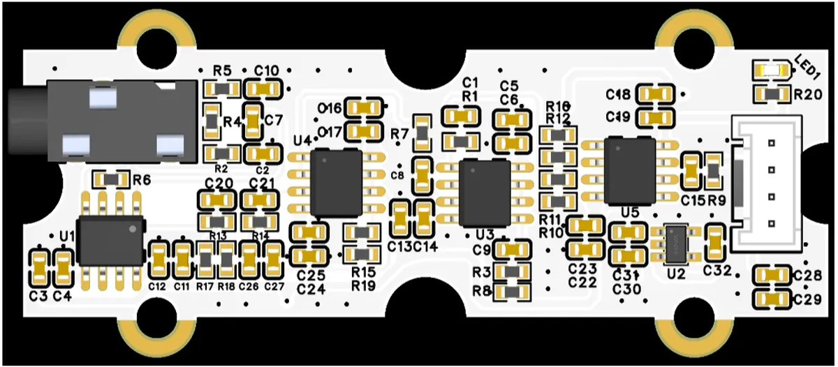
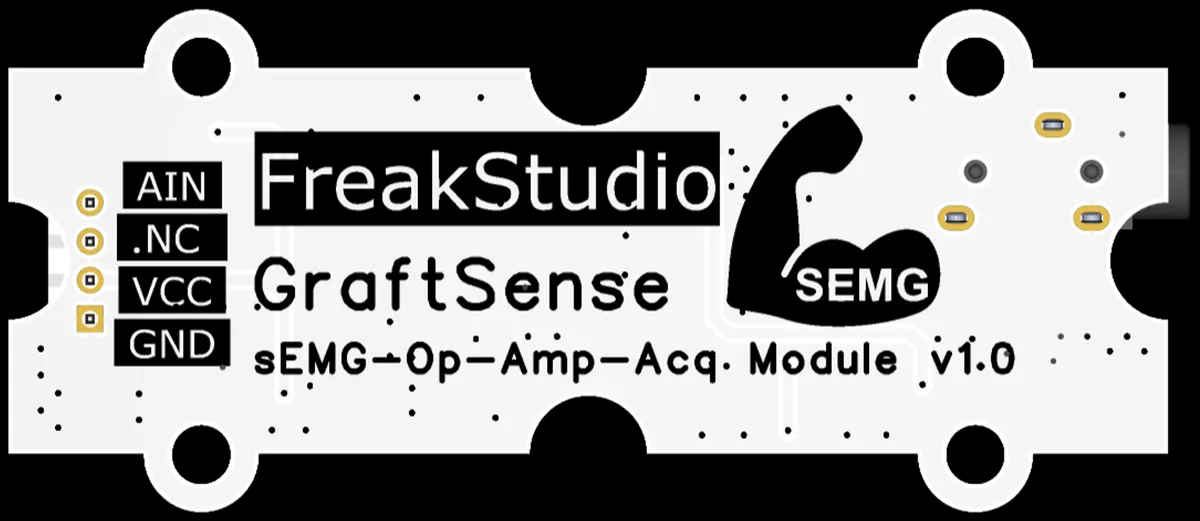
This module provides an analog interface: the ADC of the MCU only needs to read the output of AIN, which is an analog voltage signal correlated with muscle activity intensity and can be directly connected to the ADC pins of mainstream MCUs such as Arduino and STM32. Developers only need to perform simple ADC sampling and threshold judgment to quickly realize the recognition of "muscle exertion - resting" status, and easily build interesting interactive projects such as myoelectric control switches and simple motion detection, which is very suitable for entry-level developers to quickly explore the fun of myoelectric interaction.
3.3 Application Experiment
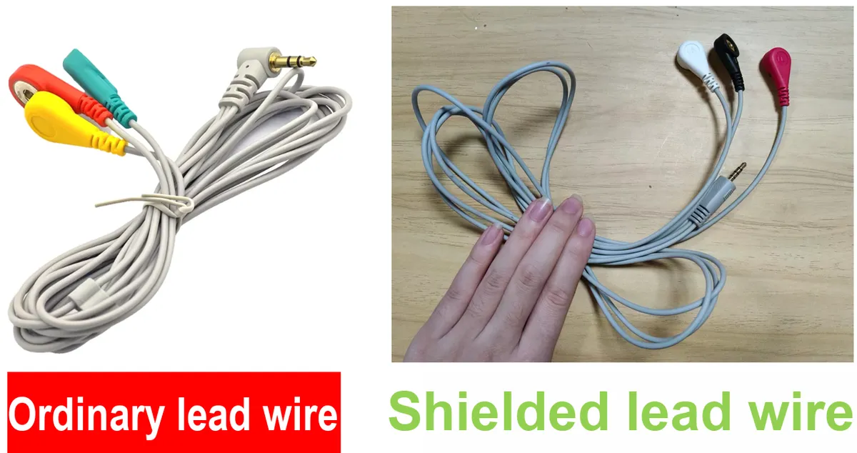
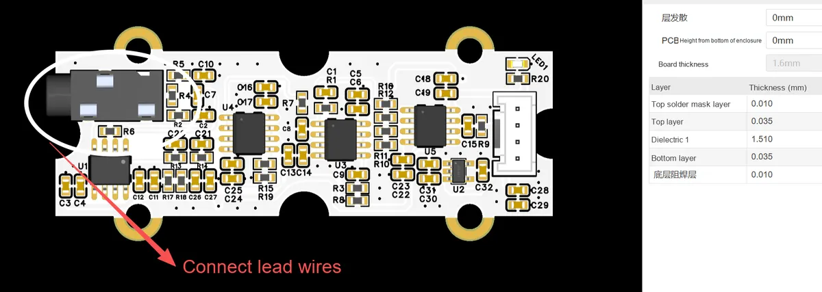
Here, we first need to connect the lead wires to the lead interface of the module. If you have high requirements for waveform accuracy, it is recommended to replace them with shielded lead wires to further reduce electromagnetic interference:
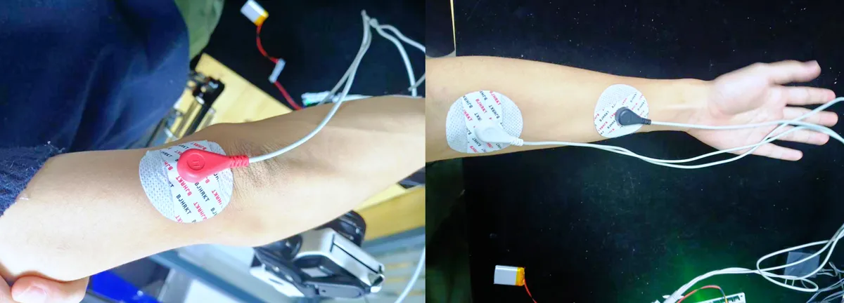
This module adopts a three-electrode differential lead method, which is compatible with the naming logic of RA ECG RA / LA / LL for electrocardiogram (ECG), and adapts to the differential acquisition requirements of surface electromyographic signals. The specific lead definitions and placement positions are as follows:
LA(Left Arm, positive signal terminalSIGNAL_IN+): Attach it to the central position of the muscle belly of the target muscle (e. g., forearm flexor/extensor)(the white interface electrode near the wrist on the right arm in the figure), which is used to collect the positive electrical signal generated by muscle activity.RA(Right Arm, signal negative terminalSIGNAL_IN-): Attach it to the edge of the muscle belly of the same muscle (the black interface electrode near the elbow on the right arm in the figure). It serves as the negative terminal of the differential input, forming a differential pair with LA to amplify the myoelectric signal.LL(Left Leg, reference electrodeGND): Attach it to the elbow (the red interface electrode on the left elbow in the figure). This site has weak muscle activity, so it can serve as a stable reference potential point to suppress common-mode interference such as 50Hz power frequency and improve signal quality.
Here, we use the GraftPort-RP2040 development board for testing, and connect the surface electromyogram signal operational amplifier acquisition module via its AIN interface to the main controller.
Here, we first use the HY2.0-4P connection cable to connect the module to the GraftPort-RP2040 development board's AIN0 interface, and you need to connect the MiniUSB data cable to the UART interface at the bottom of the main control board::
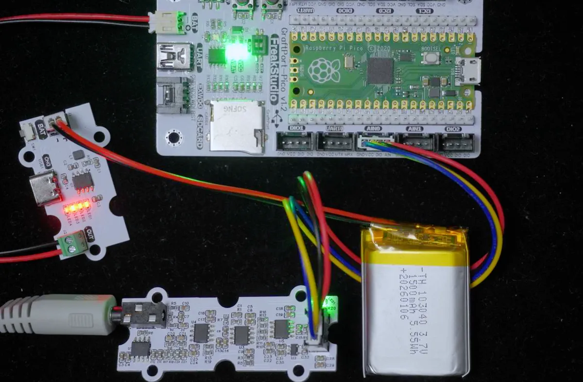
The module connections are shown in the following table:
Development Board Pins | Module Pins | Description |
Pin 26 |
|
|
Pin 19 |
| - |
Here, to eliminate the power frequency interference introduced by USB power supply, we use a lithium battery charge-discharge module based on the SY7656 chip to power the GraftPort-RP2040 development board.
Before running the code below, you first need to flash the following firmware:
RPI_PICO_ulab.uf2 913 KB
After importing the surface electromyogram signal operational amplifier type acquisition module - MicroPython driver code, copy the following main.py code into our project:
# Python env   : MicroPython v1.24.0
# -*- coding: utf-8 -*-
# @Time    : 2026/2/4 10:12 PM
# @Author  : hogeiha
# @File    : main.py
# @Description : semg_driver main program (100Hz version)

# ======================================== Import Modules =========================================

from machine import ADC, Pin, Timer, UART
import time
from ulab import numpy as np, utils
from ulab import scipy as spy

# ======================================== Global Variables ============================================

# 100Hz sampling rate (adjustable according to hardware capability)
FS = 100.0
DC_REMOVE_BASE = 0.0
# 200ms DC removal window, suppresses baseline drift
DC_WINDOW = 20
# Run flag, used to stop the program safely
running = True

# ===================== SEMG-specific filter coefficients =====================
# 1. 50Hz notch filter: suppresses power line interference (core SEMG requirement)
notch_b0 = 1.0
notch_b1 = -1.0
notch_b2 = 1.0
notch_a0 = 1.080
notch_a1 = -1.0
notch_a2 = 0.920
sos_notch = np.array(
    [[notch_b0 / notch_a0, notch_b1 / notch_a0, notch_b2 / notch_a0, 1.0, notch_a1 / notch_a0, notch_a2 / notch_a0]],
    dtype=np.float)

# 2. 0.5Hz high-pass filter: removes baseline drift (core SEMG requirement)
hp_b0 = 0.9605960596059606
hp_b1 = -1.9211921192119212
hp_b2 = 0.9605960596059606
hp_a0 = 1.0
hp_a1 = -1.918416309168257
hp_a2 = 0.9206736526946108
sos_hp = np.array([[hp_b0 / hp_a0, hp_b1 / hp_a0, hp_b2 / hp_a0, 1.0, hp_a1 / hp_a0, hp_a2 / hp_a0]], dtype=np.float)

# 3. 35Hz low-pass filter: filters high-frequency noise (adjustable as needed, typical SEMG bandwidth 20-500Hz)
lp_b0 = 0.2266686574849259
lp_b1 = 0.4533373149698518
lp_b2 = 0.2266686574849259
lp_a0 = 1.0
lp_a1 = -0.18587530329589845
lp_a2 = 0.19550632911392405
sos_lp = np.array([[lp_b0 / lp_a0, lp_b1 / lp_a0, lp_b2 / lp_a0, 1.0, lp_a1 / lp_a0, lp_a2 / lp_a0]], dtype=np.float)

# ===================== Filter state maintenance =====================
zi_notch = np.zeros((sos_notch.shape[0], 2), dtype=np.float)
zi_hp = np.zeros((sos_hp.shape[0], 2), dtype=np.float)
zi_lp = np.zeros((sos_lp.shape[0], 2), dtype=np.float)
dc_buffer = np.zeros(DC_WINDOW, dtype=np.float)
dc_idx = 0


# ======================================== Functions ============================================

def realtime_process(timer):
    global DC_REMOVE_BASE, dc_buffer, dc_idx, zi_notch, zi_hp, zi_lp

    if not running:
        return

    # 1. Acquire raw ADC data
    adc_raw = adc.read_u16()
    raw_val = adc_raw * 3.3 / 65535

    # 2. Sliding-window DC removal (suppresses baseline drift)
    dc_buffer[dc_idx] = raw_val
    dc_idx = (dc_idx + 1) % DC_WINDOW
    DC_REMOVE_BASE = np.mean(dc_buffer)
    raw_val_dc = raw_val - DC_REMOVE_BASE

    # 3. Multi-stage filtering (power line interference + baseline drift + high-frequency noise)
    raw_arr = np.array([raw_val_dc], dtype=np.float)
    notch_arr, zi_notch = spy.signal.sosfilt(sos_notch, raw_arr, zi=zi_notch)
    hp_arr, zi_hp = spy.signal.sosfilt(sos_hp, notch_arr, zi=zi_hp)
    filtered_arr, zi_lp = spy.signal.sosfilt(sos_lp, hp_arr, zi=zi_lp)
    filtered_val = filtered_arr[0] * 1.5  # Amplitude calibration

    # 4. Serial output (raw value + filtered value)
    uart_str = f"{raw_val_dc:.6f},{filtered_val:.6f}\r\n"
    uart.write(uart_str.encode('utf-8'))

    # 5. Debug print
    print_str = f"Original value:{raw_val_dc:.6f}, Filtered value:{filtered_val:.6f}"
    print(print_str)

# ======================================== Custom Classes ============================================

# ======================================== Initialization ==========================================

# Power-on delay of 3 s
time.sleep(3)
print("FreakStudio: SEMG Driver (100Hz version)")

# ADC initialization
adc = ADC(Pin(26))

# Serial port initialization
uart = UART(0, baudrate=115200, tx=Pin(0), rx=Pin(1), bits=8, parity=None, stop=1)

print("===== Surface Electromyography System (100Hz Version) =====")
print(f"Sampling Frequency: {FS}Hz | 50Hz Notch Filter | Baseline Drift Removal")
print("Press Ctrl+C/Thonny Stop Button to terminate the programn")

uart.write("===== Surface Electromyography System (100Hz Version) =====rn".encode('utf-8'))
uart.write(f"Sampling Frequency: {FS}Hz | Output: Raw Value, Filtered Valuern".encode('utf-8'))

# Start timer sampling
timer = Timer(-1)
timer.init(freq=int(FS), mode=Timer.PERIODIC, callback=realtime_process)

# ========================================  Main Program  ===========================================

# Main thread waits for the stop signal
try:
    while running:
        time.sleep(0.1)
except KeyboardInterrupt:
    running = False
    timer.deinit()
    print("nThe program has stopped!")
    uart.write("nThe program has stopped!rn".encode('utf-8'))
The above code acquires surface electromyography (sEMG) raw signals via ADC at a sampling rate of 100 Hz. First, it removes the DC component through a sliding window to suppress baseline drift, then processes the signal sequentially with a 50Hz notch filter, a 0.5Hz high-pass filter, and a 35Hz low-pass filter to suppress power line interference and noise. Finally, it outputs the DC-removed raw values and the filtered values via the serial port and Console, and supports safely stopping the timer sampling through a keyboard interrupt.
When burning the code, the terminal output is as follows:
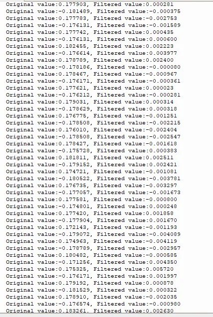
The original value and the filtered value are printed in the timer.
The following are the waveforms in various states obtained by connecting the on-board UART to the serial port plotter. First, complete the configuration of the SerialPlot serial port plotter:
- Configure serial port parameters: On the
Porttab, select the correct serial port (e. g.COM4), set the baud rate to 115200, data bits to 8, stop bits to 1, and no parity bit - Click "Open": After confirming the configuration is correct, click the
Openbutton in the upper right corner to open the serial port

- Select the data format: switch to the
Data Formattab and select the "ASCII" format. For single-channel data transmission, the comma is selected as the default data delimiter
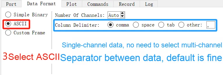
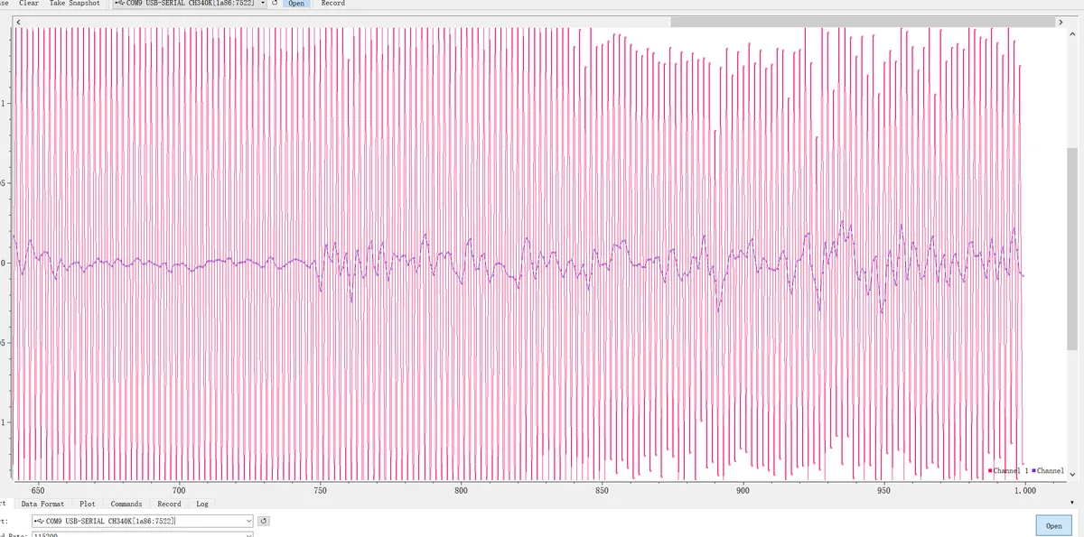
As can be seen, the corresponding waveform is output:
When exerting force:
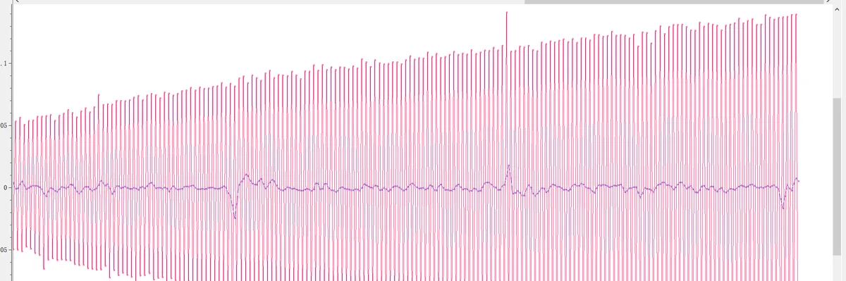
At rest:
Overall:
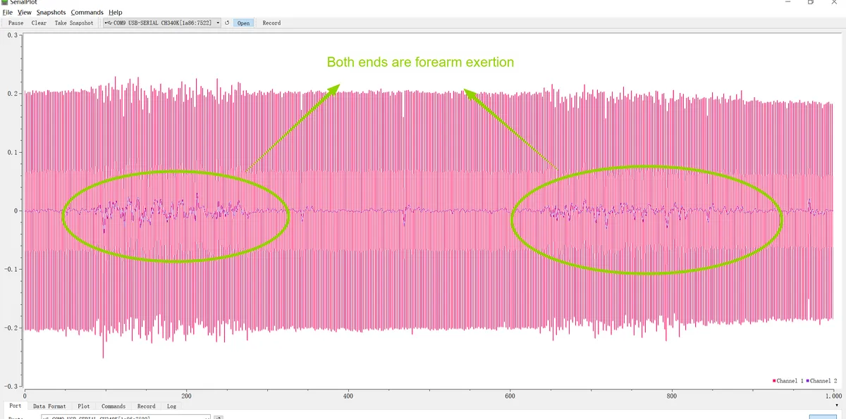
During the two forearm force-exertion periods, the weak low-frequency fluctuations (marked by green circles) in the purple channel are mainly motion artifacts caused by muscle contraction, while the large-amplitude high-frequency fluctuations in the pink channel are primarily a superposition of noise and artifacts. We can roughly distinguish between muscle activation and resting states based on the presence or absence of signal fluctuations.
When using this module, please note the following:
- On the one hand, muscles are susceptible to motion artifacts in the 0.5Hz~10Hz frequency band when exerting force; the amplitude of such artifacts is far greater than that of real microvolt-level sEMG signals, and the filter circuit of the module cannot suppress artifacts in this frequency band. Meanwhile, the 100Hz sampling rate fails to correctly acquire real sEMG signals in the 20Hz~500Hz frequency band, which results in the acquired signal being dominated by artifacts and the features of the real sEMG being masked;
- On the other hand, this module is only applicable to entry-level scenarios for beginners to distinguish between muscle activation and resting states; due to insufficient signal quality, it cannot meet the usage requirements of professional scenarios such as electromyographic signal spectrum analysis, rehabilitation assessment, and precise motion recognition.
4. Drivers
RPI_PICO_ulab.uf2 913 KB
semg_driver.rar 2 KB
5. BOM & Recommended Alternative Parts
None.
VI. Revision History
Document Version | Date of Modification | Modifier | Revised Content |
v1.0 | 2025-11-22 | Li Zisheng | Initialize Document |
v1.1 | 2026-02-12 | Xin Ruili | Create an open version of the document based on the internal document version v1.0. |
VII. Relevant Materials
7.1 Chip Datasheet
C356702_Precision Op Amp_AD8552M-TR_Datasheet_Huaguan AD8551-AD8552-AD8554(English)+202411.PDF 1.7 MB
tps60403.pdf 1.6 MB
C34250_Instrumentation Amplifier_AD8226ARZ-R7_Datasheet_WJ249173.PDF 691 KB
7.2 Unique Icons for PCB Silk Screen