Contents
- I. Module Introduction
- 2. Introduction to Main Chips
- 2.1 Chip Overview
- 2.2 Pin Definition
- 2.3 Functional Block Diagram
- 2.4 Performance Parameters
- 2.5 Reference Circuit
- 2.6 Chip Configuration
- 2.7 Communication Interfaces and Related Protocols
- 2.8 PCB Routing Precautions
- III. Instructions for Circuit Engineering and Module Usage
- 3.1 Circuit Source Engineering
- 3.2 Module Usage Instructions
- 3.3 Application Experiment
- 4. Drivers
- 5. BOM & Recommended Alternative Parts
- VI. Revision History
- VII. Relevant Materials
- 7.1 Chip Datasheet
- 7.2 Unique Icons for PCB Silk Screen
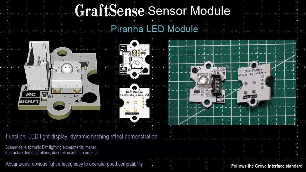
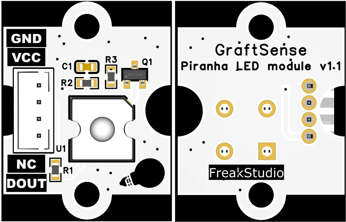
I. Module Introduction
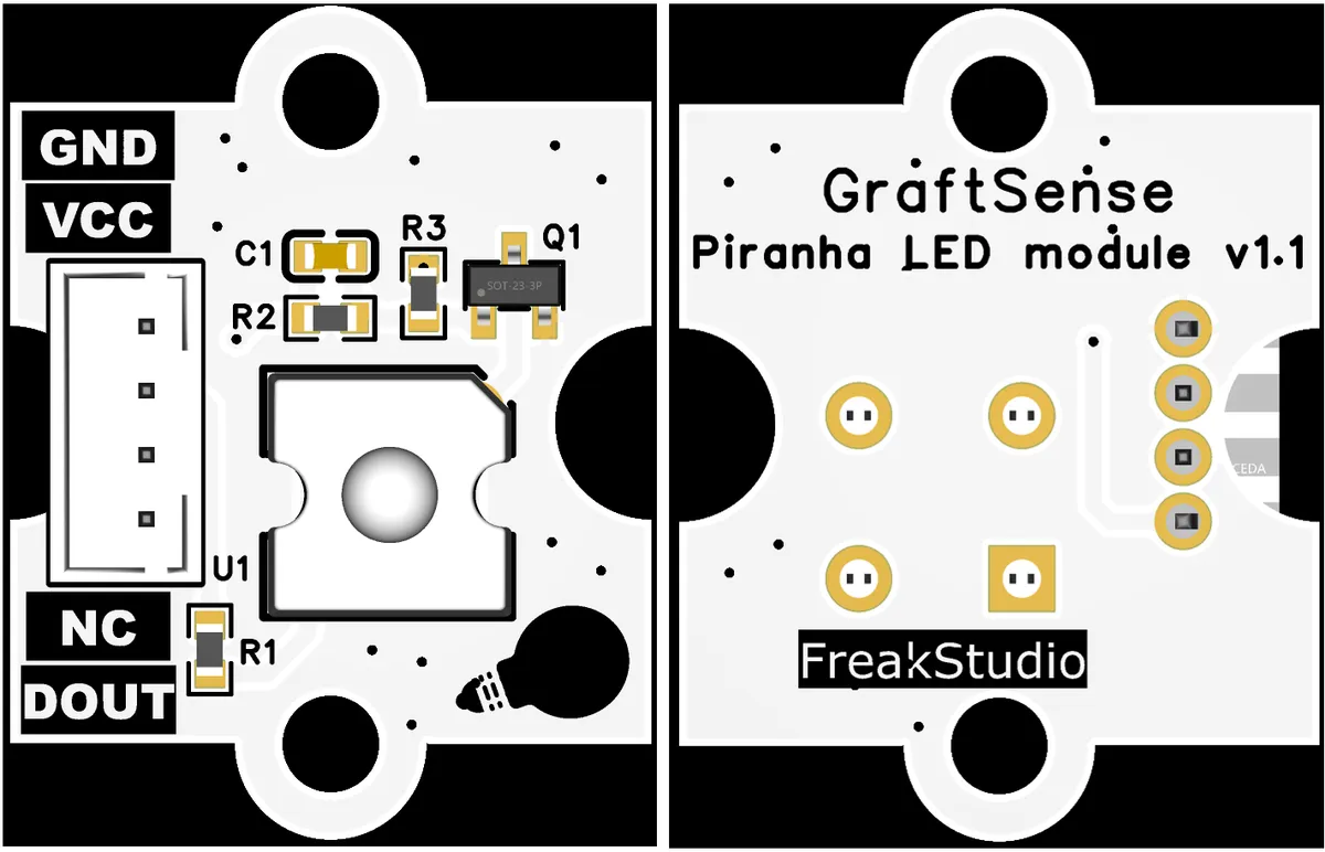
Piranha LED module is driven via S9013-E triode switching circuit for the LJF5VEXC254 model LED. It should be noted that forward soldering only supports emerald green and blue LEDs; red and yellow LEDs require reverse soldering to adapt to their electrical characteristics. Suitable for high-brightness light signal indication or driving scenarios in embedded systems, it provides flexible LED light output solutions for devices.
2. Introduction to Main Chips
2.1 Chip Overview
LJF5VEXC254 is an ultra-orange light GaAlInP/Si LED chip with a transparent lens. It features high brightness, high reliability, low voltage, a narrow viewing angle, is lead-free and complies with the RoHS standard. This single chip has a power dissipation of 140mW, a reverse voltage of 5V, a continuous forward current of 50mA, an operating temperature range of -25℃ to 85℃, a forward voltage of 2.2~2.8V (IF = 50mA), a dominant wavelength of 624nm, and a luminous intensity of 9500mcd, making it suitable for optical signal indication scenarios that have high requirements for brightness and reliability.
2.2 Pin Definition
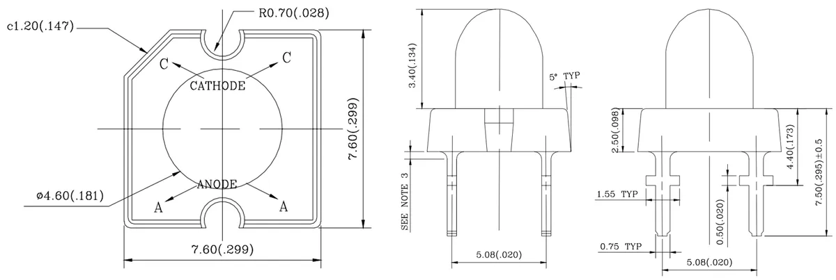
The LED pins are divided into the anode (ANODE, corresponding to pin A) and the cathode (CATHODE, corresponding to pin C). The two pins marked ANODE are the positive electrodes, which need to be connected to the positive terminal of the power supply; the two pins marked CATHODE are the negative electrodes, which need to be connected to the negative terminal (or ground) of the power supply.
2.3 Functional Block Diagram
None.
2.4 Performance Parameters
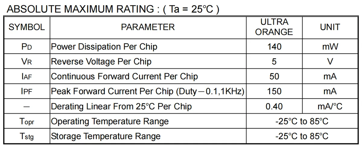
The absolute maximum rated value of the LED chip (super orange light model) is: single chip power consumption 140mW, reverse voltage 5V, continuous forward current 50mA, peak forward current 150mA (duty cycle 0.1, 1KHz), temperature derating factor 0.40mA/℃, the operating and storage temperature range is - 25 ℃ to 85 ℃, these parameters define the ultimate operating conditions of the chip and must be strictly followed to ensure reliability.
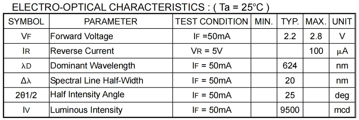
The LED chip exhibits the following optoelectronic characteristics at 25°C: forward voltage VF typically 2.2 V (maximum 2.8 V at IF = 50 mA), reverse current IR maximum 100 μA at VR = 5 V), dominant wavelength λD typically 624 nm, spectral half-width Δλ 20 nm, half-intensity angle 25°, and luminous intensity Iv typically 9500 mcd (all measured at IF = 50 mA); these parameters define its core optoelectronic properties including electro-optic conversion, emission color, radiation angle and brightness.
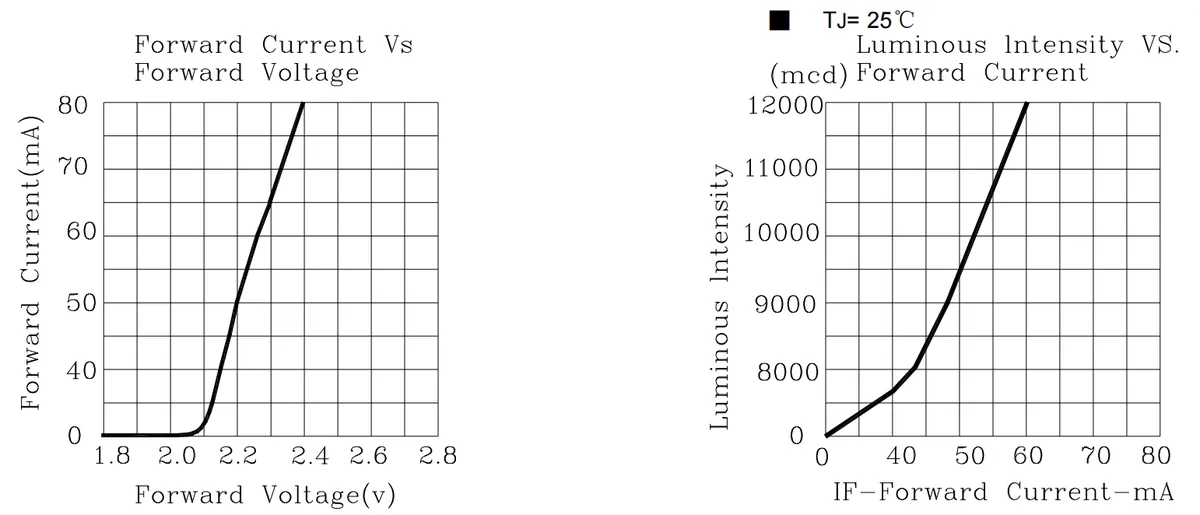
These two graphs are the characteristic curves of LED, which are used to demonstrate the correlation between its electrical properties and optical properties. The specific analysis is as follows:
- The left side shows the relationship curve between forward current and forward voltage: The horizontal axis represents forward voltage (range: 1.8~2.8V), and the vertical axis represents forward current (range: 0~80mA). It can be seen that when the voltage is lower than 2.0V, the forward current is almost 0; when the voltage exceeds 2.2V, the current rises rapidly, which reflects the conduction characteristic of
LEDthat "the current increases sharply once the conduction voltage is reached". - The graph on the right illustrates the relationship between luminous intensity and forward current: the horizontal axis represents forward current (range: 0~80mA), and the vertical axis represents luminous intensity (range: 0~12000mcd). The luminous intensity rises as the forward current increases, and the brightness growth accelerates significantly once the current exceeds 40mA, indicating that the luminous brightness of this
LEDis positively correlated with the current, with a more pronounced brightness improvement under high current conditions.
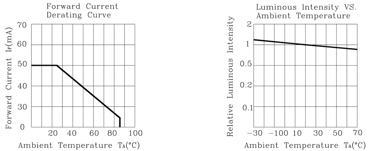
The above two figures indicate that this LED needs to have its forward current reduced as the ambient temperature rises to ensure reliability, and its luminous intensity attenuates slightly with increasing temperature.
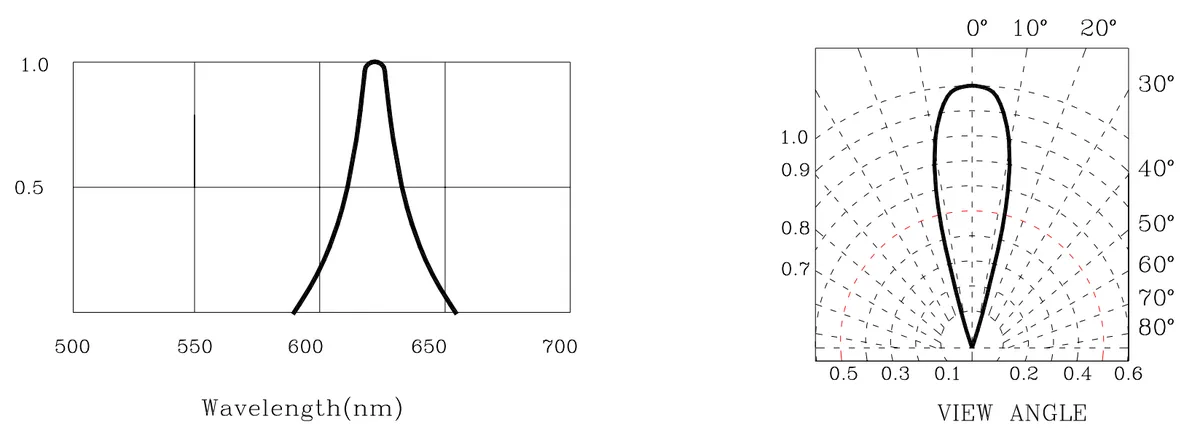
The above two figures indicate that this LED has a dominant wavelength concentrated in the orange light range of 600-650nm, a relatively narrow viewing angle, and its light is concentrated within a small angle range.
2.5 Reference Circuit
None.
2.6 Chip Configuration
None.
2.7 Communication Interfaces and Related Protocols
None.
2.8 PCB Routing Precautions
None.
III. Instructions for Circuit Engineering and Module Usage
3.1 Circuit Source Engineering
To obtain the circuit source project, please follow the official account [Freak Embedded]
3.2 Module Usage Instructions
The schematic diagram of this module is shown below:
SCH_Piranha LED Module_v1.0_2025-09-14.pdf 1.1 MB
This module provides an output interface DOUT: when DOUT inputs a high level, the triode Q1 turns on, and the LED lights up; when DOUT inputs a low level, the triode turns off, and the LED turns off.
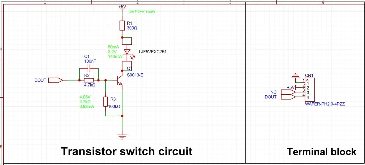
This triode switching circuit uses S9013-E (an NPN type triode) as the core switching element; the DOUT digital interface receives the control signal, which, after being processed by the filter circuit composed of R2 (4.7kΩ) and C1 (100nF), controls the on/off state of the triode.When the triode is turned on, the + 5V power supply drives R1 (300Ω current-limiting resistor) to make the LJF5VEXC254 LED emit light, R3 (100kΩ bias resistor) provides a stable bias current for the triode, so as to realize the switching control of the LED by digital signals. This is a typical circuit application of "triode driving load" in embedded systems.
3.3 Application Experiment
Here, we use the GraftPort-RP2040 development board for testing, and the piranha LED module uses the DIO interface to communicate with the main controller.
Here, we first use the HY2.0-4P cable to connect the module to the GraftPort-RP2040 development board's DIO0 interface:
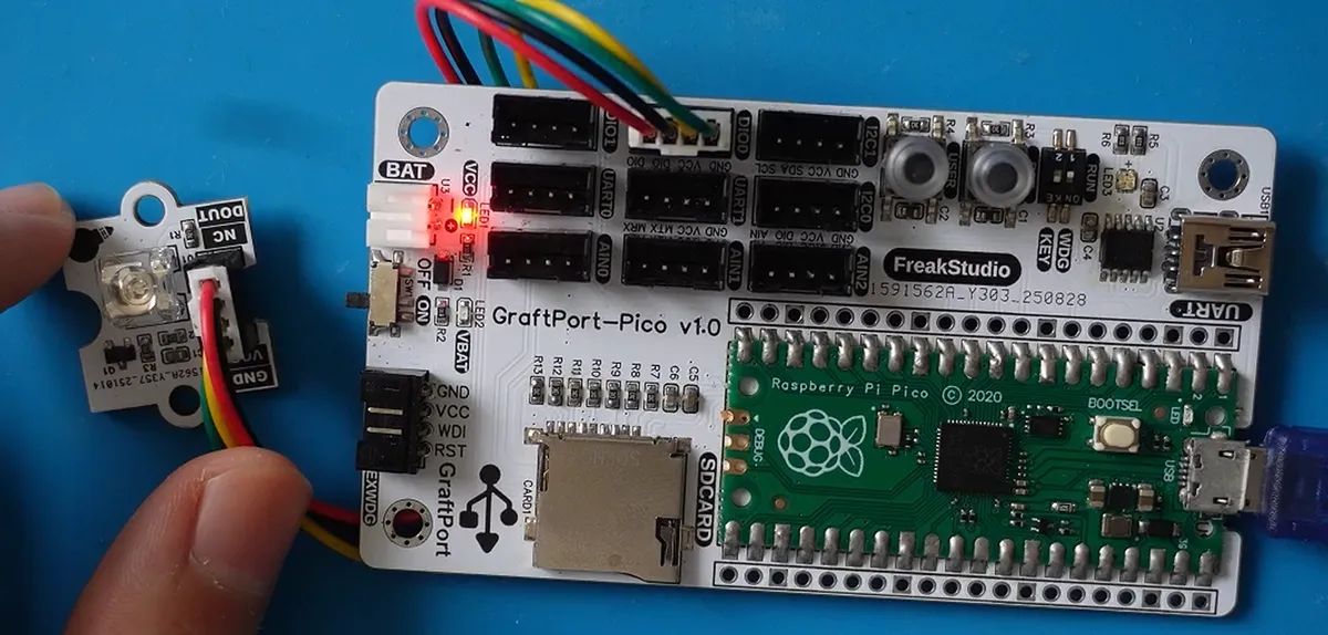
The module connections are shown in the following table:
Development Board Pins | Module Pins | Description |
Pin 6 |
| Level output/PWM output pins on the MCU |
Pin 7 |
| Do not use |
Here, we can import the module driver library code via the mip tool. Below are the usage commands for the mpremote tool:
mpremote mip install github:FreakStudioCN/GraftSense-Drivers-MicroPython/lighting/piranha_led_driveAfter importing the PiranhaLED-MicroPython driver code, copy the following main.py code into our project:
# Python env   : MicroPython v1.23.0
# -*- coding: utf-8 -*-
# @Time    : 2025/08/19 12:45
# @Author  : 零高幸
# @File    : main.py
# @Description : Test the PiranhaLED driver (standard main entry)
# @License : CC BY-NC 4.0

# ======================================== Import Modules =========================================

# Import standard libraries
import time
# Import the custom Piranha LED driver module
from piranha_led import PiranhaLED, POLARITY_CATHODE, POLARITY_ANODE

# ======================================== Global Variables ============================================

# Test configuration
LED_PIN = 6
TEST_COUNT = 3
BLINK_INTERVAL = 1.0
# Set to True for a common-anode LED
IS_ANODE = False

# ======================================== Functions ============================================

# ======================================== Custom Classes ============================================

# ======================================== Initialization Configuration ========================================

# Power-on delay of 3 s
time.sleep(3)
# Print debug message
print("FreakStudio: Using Running Led Code")

# Initialize the LED object
led = PiranhaLED(
    pin_number=LED_PIN,
    polarity=POLARITY_ANODE if IS_ANODE else POLARITY_CATHODE
)

# ======================================== Main Program ==============================================

try:
    # Run the blink test 3 times
    for _ in range(TEST_COUNT):
        led.on()
        time.sleep(BLINK_INTERVAL)

        led.off()
        time.sleep(BLINK_INTERVAL)

    # Demonstrate the toggle function
    # Turn the LED on
    led.toggle()
    time.sleep(BLINK_INTERVAL)

    # Turn the LED off
    led.toggle()
    time.sleep(BLINK_INTERVAL)

except KeyboardInterrupt:
    # User manual interrupt (e.g., Ctrl+C)
    pass
except Exception as e:
    # Catch other exceptions (optional: log them)
    pass
finally:
    # Make sure the LED is off and exit safely
    led.off()
Burn the code, open the terminal, and use the mpremote tool to connect to the main controller. The output is as follows:

It can be seen that the lights will illuminate sequentially in accordance with the process defined in the code.
4. Drivers
5. BOM & Recommended Alternative Parts
None.
VI. Revision History
Document Version | Date of Modification | Modifier | Revised Content |
v1.0 | 2025-08-19 | Zero Kōkō | Initialize Document |
v1.1 | 2025-11-03 | Li Zisheng | Added PCB routing precautions for Version 2.8 Revised Section 3, Instructions for Circuit Source Project and Module Usage, and added a secondary heading: 3.1 Circuit Source Engineering, 3.2 Module Usage Instructions, 3.3 Application Experiments The BOM sheet has not been finally checked, the driver has not been re-verified, and the 3.3 application experiment Not yet specified. |
v1.2 | 2025-12-29 | Li Zisheng | Added application experiments and production files |
v1.3 | 2025-12-31 | Xin Ruili | Create an open version of the document based on the internal document version v1.2. |
v1.4 | 2026-03-29 | Xin Ruili | Modified the application experiment section |
VII. Relevant Materials
7.1 Chip Datasheet
C2988062_LED_LJF5VEXC254_Datasheet_WJ129864.PDF 428 KB
7.2 Unique Icons for PCB Silk Screen