Contents
- I. Module Introduction
- 2. Introduction to Main Chips
- 2.1 Chip Overview
- 2.2 Pin Definition
- 2.3 Functional Block Diagram
- 2.4 Performance Parameters
- 2.5 Reference Circuit
- 2.6 Chip Configuration
- 2.7 Communication Interfaces and Related Protocols
- 2.8 PCB Routing Precautions
- III. Circuit Engineering
- 3.1 Circuit Source Engineering
- 3.2 Module Usage Instructions
- 3.3 Application Experiment
- 4. Drivers
- 5. BOM & Recommended Alternative Parts
- VI. Revision History
- VII. Relevant Materials
- 7.1 Chip Datasheet
- 7.2 Unique Icons for PCB Silk Screen
I. Module Introduction
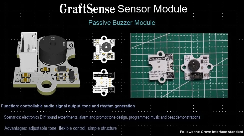
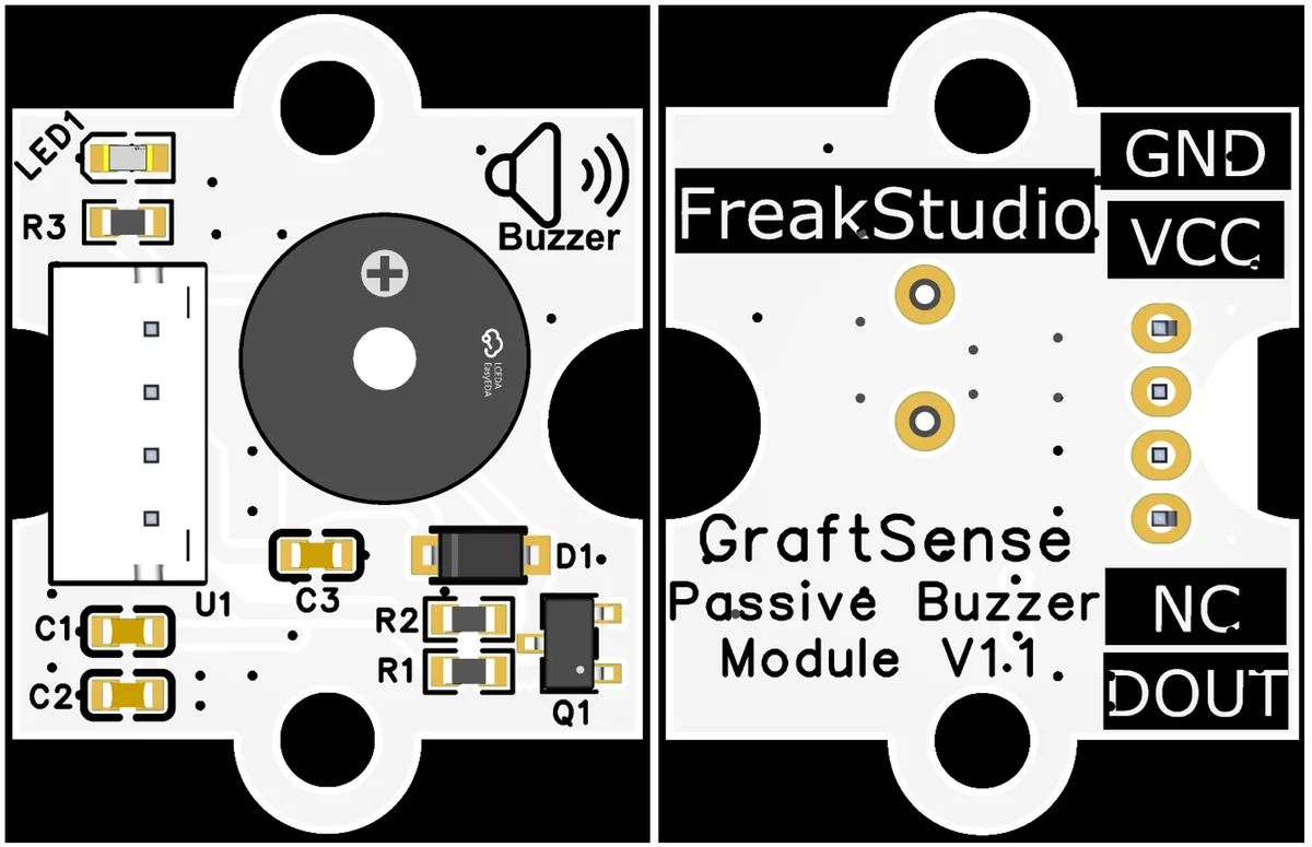
Passive Buzzer Module which integrates a passive buzzer, a triode driving circuit, an indicator light, a filter circuit and a sensor interface, and is driven by PWM signals. It can realize the function of adjustable audio prompt, and is designed with power filtering and status indication functions. It is suitable for sound alarm or prompt scenarios of various electronic systems, and provides a flexible audio feedback solution for equipment.
2. Introduction to Main Chips
A buzzer (Buzzer) is an electronic component used to generate sound, which is widely applied in various devices to produce warning tones, prompt tones or other sound effects. According to different working principles, buzzers mainly fall into the following types: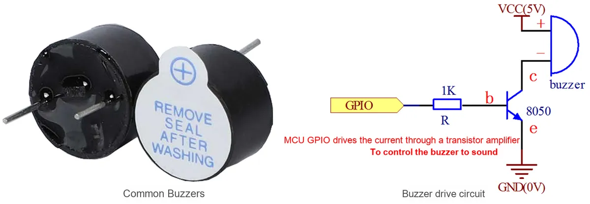
- Active Buzzer (
Active Buzzer): An active buzzer has an integrated oscillation circuit inside that generates an oscillation signal of a fixed frequency, which in turn drives the piezoelectric buzzer to produce sound via the piezoelectric effect. Simply put, when voltage is applied, the piezoelectric material undergoes mechanical deformation to generate sound; there are also some active buzzers that operate on the electromagnetic vibration principle – when current flows through the coil, a magnetic field is generated, which causes an iron piece or diaphragm to vibrate, thereby producing sound.
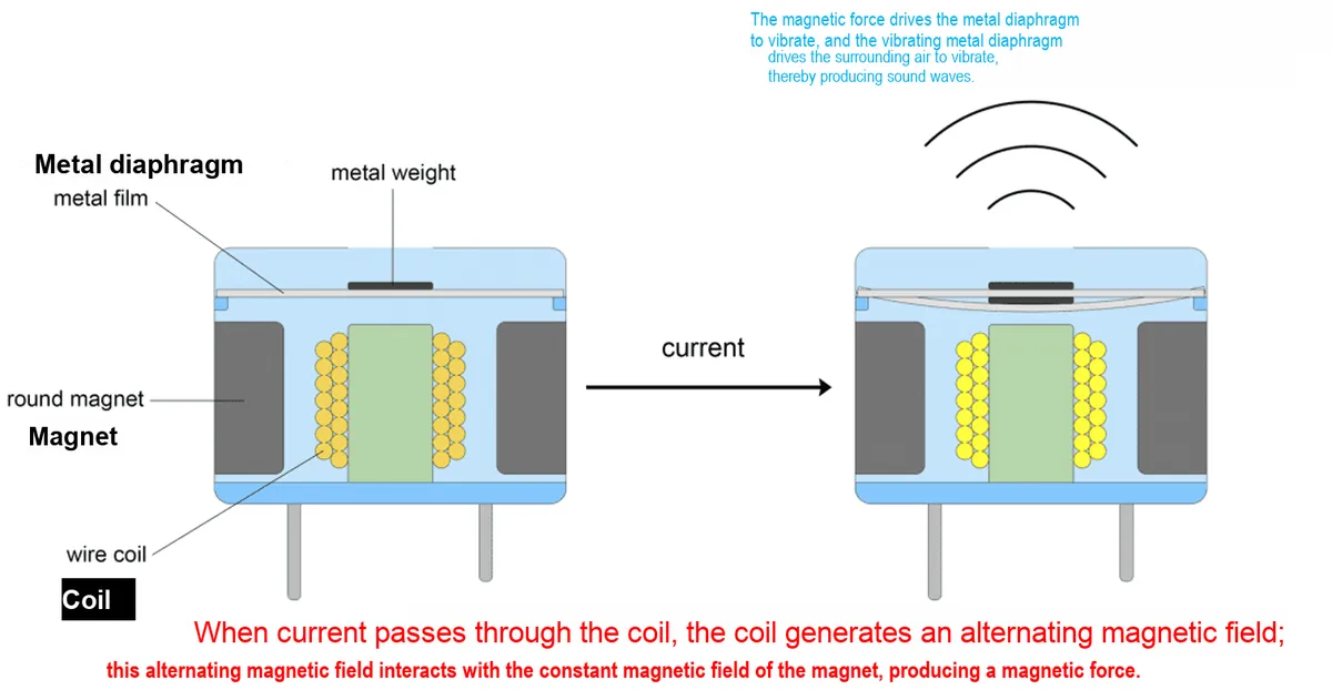
- Passive Buzzer (
Passive Buzzer): A passive buzzer has no internal oscillation circuit. It consists of a coil, an iron piece or a diaphragm, and requires an external signal to drive it to produce sound.
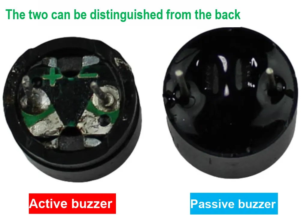
In practical applications, the two have their respective focuses:
- Active buzzer: It is suitable for scenarios requiring simple and fixed sound, but its drawback is that the frequency of the sound it generates is fixed and cannot be adjusted.
- Passive Buzzer: We can adjust the frequency and duty cycle of the external signal to change the sound frequency and pitch produced by the buzzer, which is suitable for scenarios requiring multiple tones or audio effects, such as music playback, alarm systems, etc.
For the driving circuit of the passive buzzer module, its core component is the triode, which functions to amplify the weak control signal output by the microcontroller unit (MCU) and provide sufficient power for the passive buzzer to make it emit a clear sound.
2.1 Chip Overview
This chip is an electromagnetic passive buzzer of Huaneng brand QMB-09B-03 model, which is suitable for audio prompt or alarm scenarios of various electronic systems, and needs to cooperate with an external drive circuit to realize the sound feedback function.
2.2 Pin Definition
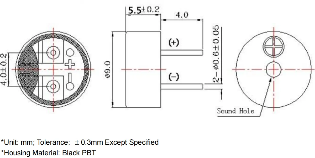
This passive buzzer has two pins, namely the positive pole (+) and the negative pole (-). The pin marked "(+)" is the positive power input terminal, which needs to be connected to the positive voltage output terminal of the drive circuit; the pin marked "(-)" is the negative power input terminal, which needs to be connected to the ground or the negative output terminal of the drive circuit.
2.3 Functional Block Diagram
None.
2.4 Performance Parameters
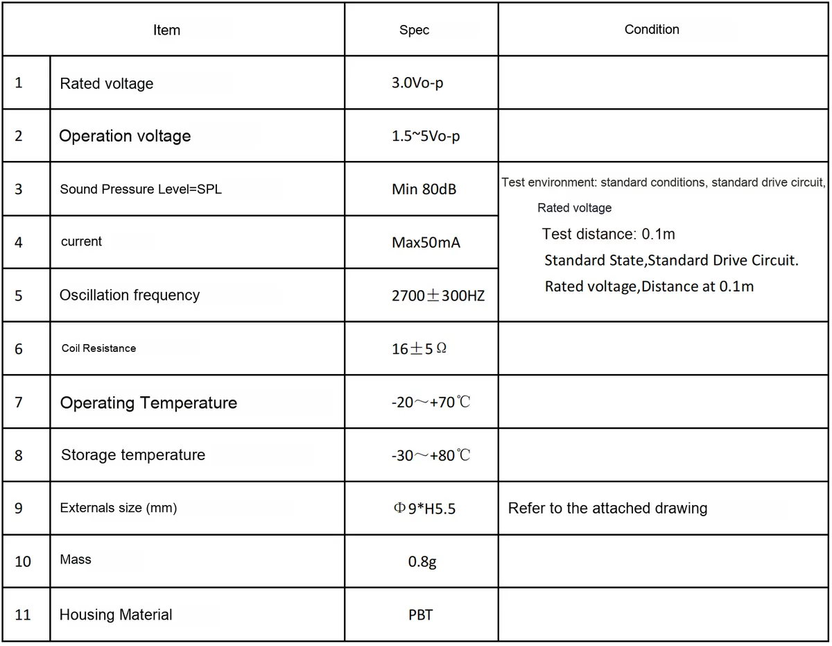
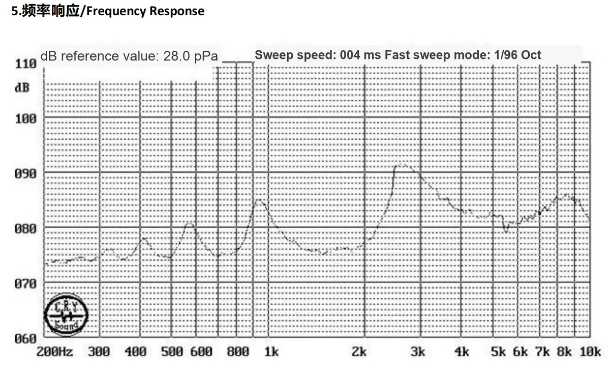
This frequency response curve clearly demonstrates the acoustic characteristics of the passive buzzer: within the test frequency range of 200 Hz to 10 kHz, its sound pressure level fluctuates significantly with frequency changes. The resonance frequency band around 3 kHz yields the highest sound pressure (close to 90 dB), making it the frequency band with optimal sound generation efficiency. In contrast, the sound pressure in the low-frequency band (200 Hz-1 kHz) and high-frequency band (above 4 kHz) is relatively stable, maintaining at approximately 70-85 dB and 80 dB respectively, which provides an intuitive basis for frequency selection in different scenarios.
2.5 Reference Circuit
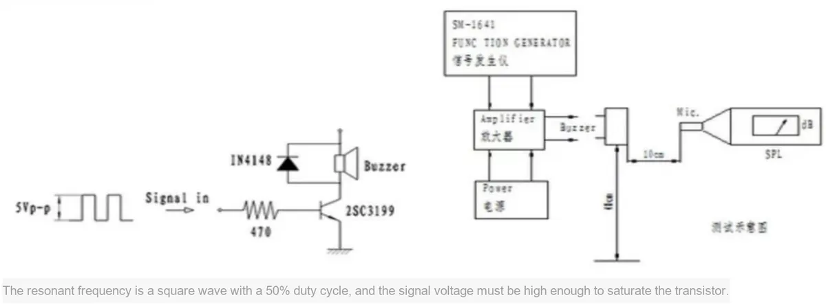
2.6 Chip Configuration
None.
2.7 Communication Interfaces and Related Protocols
None.
2.8 PCB Routing Precautions
No special requirements.
III. Circuit Engineering
3.1 Circuit Source Engineering
To obtain the circuit source project, please follow the official account [Freak Embedded]
3.2 Module Usage Instructions
The schematic diagram of this module is shown below:
SCH_Passive Buzzer Module_v1.1_2025-11-03.pdf 1.8 MB
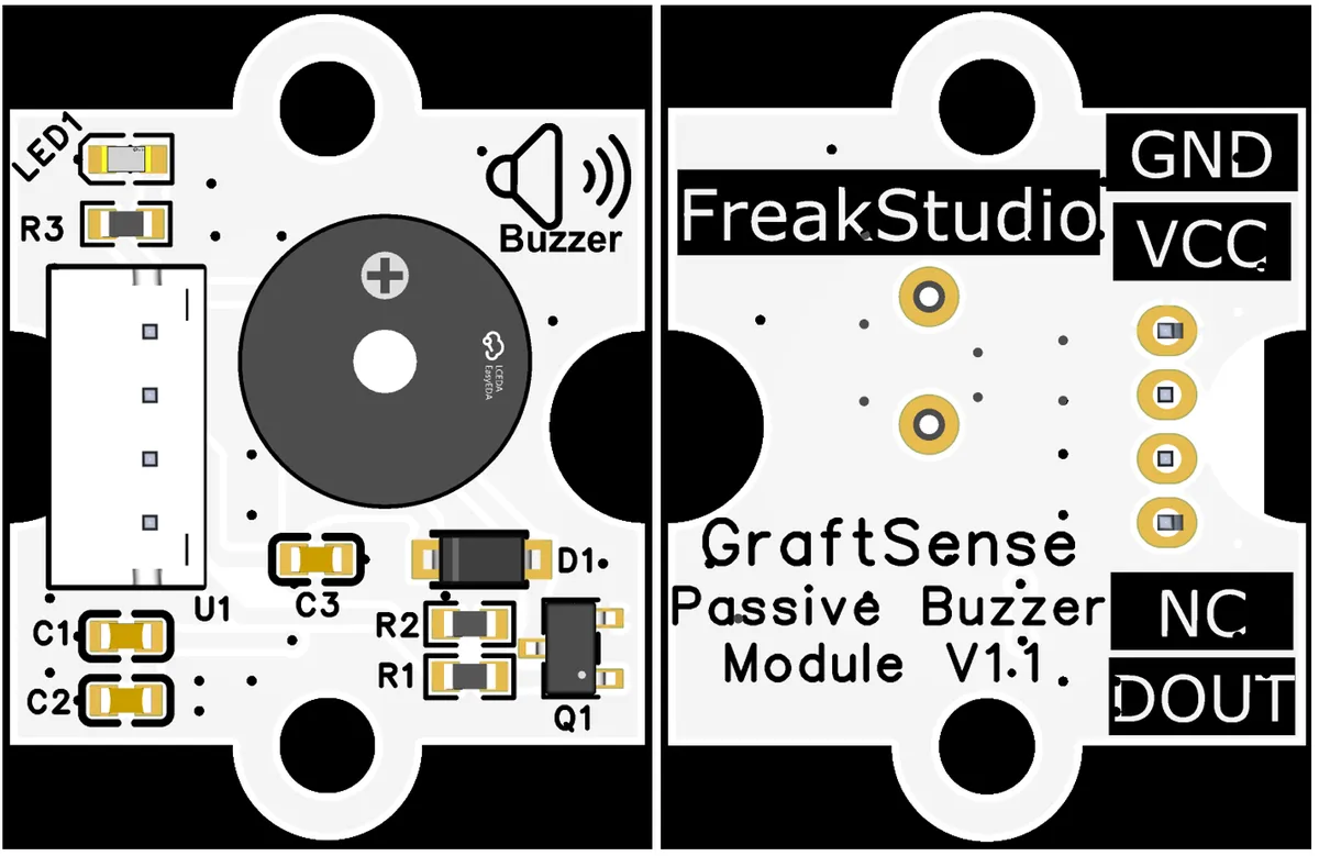
This module provides the DOUT interface: the main control unit outputs PWM waves through the DOUT pins to control the buzzer to generate sound.
It is recommended that the output PWM waveform has a frequency of around 3000 Hz.
3.3 Application Experiment
Here, we use the GraftPort-RP2040 development board for testing, and the passive buzzer module uses the DIO interface to communicate with the main controller.
Here, we first use the HY2.0-4P cable to connect the module to the GraftPort-RP2040 development board's DIO0 interface:
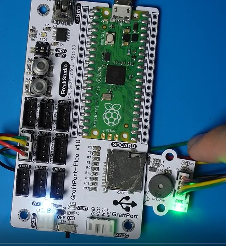
The module connections are shown in the following table:
Development Board Pins | Module Pins | Description |
Pin 6 |
| MCU's PWM output pin / high-low level output pin |
Pin 7 |
| - |
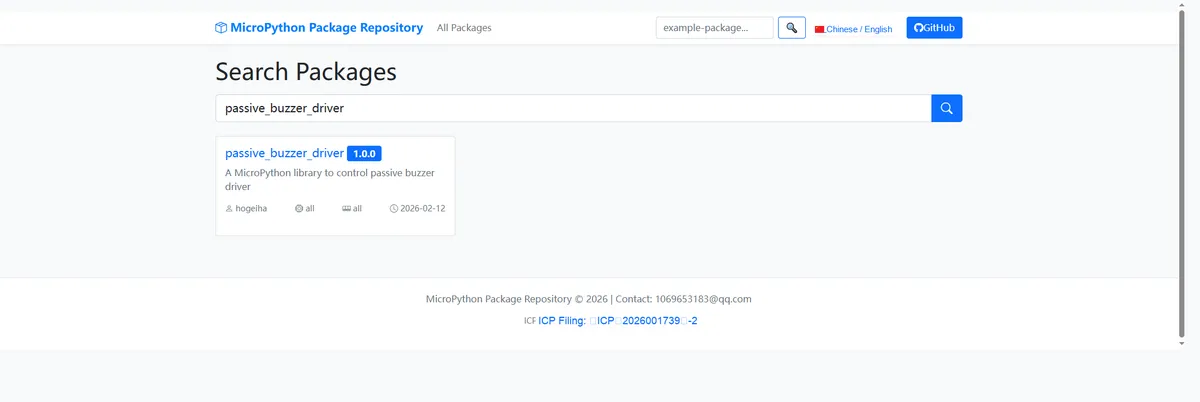
Here, we need to search for the relevant driver packages on uPyPI: https://upypi.net/zh/
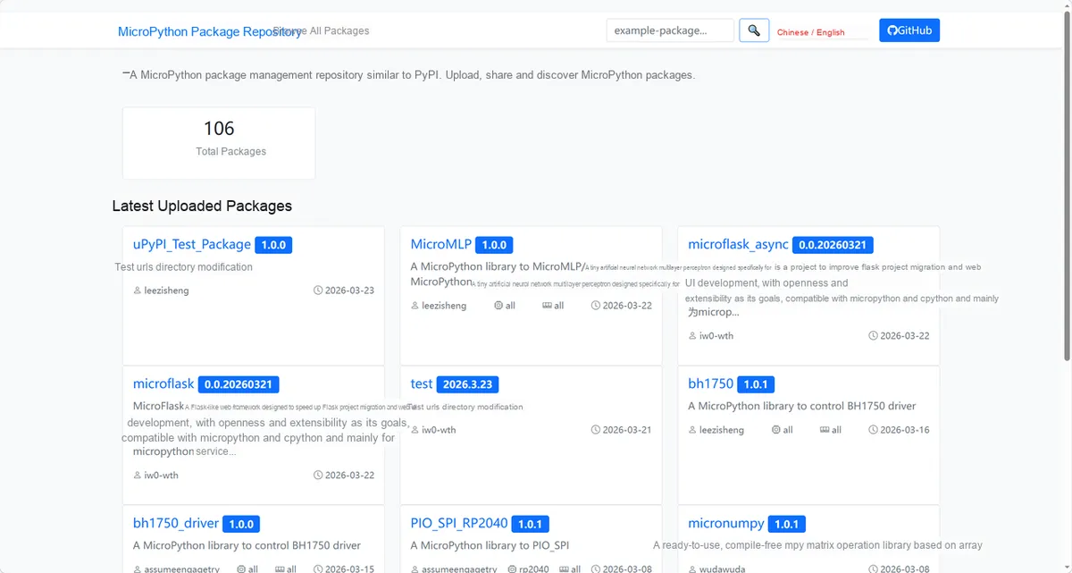
Enter passive_buzzer_driver to search, and the following will be displayed:
Click to copy the local installation command:
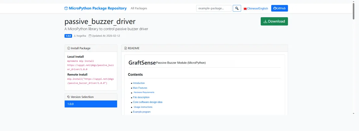
Here, we can import the module driver library code via the mip tool. Below are the usage commands for the mpremote tool:
mpremote mip install github:FreakStudioCN/GraftSense-Drivers-MicroPython/misc/passive_buzzer_driverAfter importing the buzzer driver - MicroPython driver code, copy the following main.py code into our project:
# Python env   : MicroPython v1.23.0
# -*- coding: utf-8 -*-
# @Time    : 2024/9/19 9:09 PM
# @Author  : Li Qingshui
# @File    : main.py
# @Description : PWM class usage, drive a buzzer to play MIDI music

# ======================================== Import Modules =========================================

# Import time-related modules
import time
# Import the buzzer driver class
from buzzer import Buzzer

# ======================================== Global Variables ============================================

# Melody and rhythm of Twinkle Twinkle Little Star: each note and its duration
MELODY = [
    ('C4', 400), ('C4', 400), ('G4', 400), ('G4', 400), ('A4', 400), ('A4', 400), ('G4', 800),
    ('F4', 400), ('F4', 400), ('E4', 400), ('E4', 400), ('D4', 400), ('D4', 400), ('C4', 800),
    ('G4', 400), ('G4', 400), ('F4', 400), ('F4', 400), ('E4', 400), ('E4', 400), ('D4', 800),
    ('G4', 400), ('G4', 400), ('F4', 400), ('F4', 400), ('E4', 400), ('E4', 400), ('D4', 800),
    ('C4', 400), ('C4', 400), ('G4', 400), ('G4', 400), ('A4', 400), ('A4', 400), ('G4', 800),
    ('F4', 400), ('F4', 400), ('E4', 400), ('E4', 400), ('D4', 400), ('D4', 400), ('C4', 800)
]

# ======================================== Functions ============================================

# ======================================== Custom Classes ============================================

# ======================================== Initialization ==========================================

# Power-on delay of 3 s
time.sleep(3)
# Print debug information
print("FreakStudio : Use PWM to drive a buzzer to play MIDI music")
# Initialize the buzzer object
buzzer = Buzzer(pin=6)

# ========================================  Main Program  ===========================================

# Play the music in a loop
while True:
    # Play the melody "Twinkle, Twinkle, Little Star"
    buzzer.play_melody(MELODY)
Burn the code, open the terminal, and use the mpremote tool to connect to the main controller. The output is as follows:
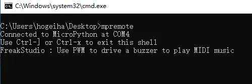
We can see that the buzzer module plays music.
4. Drivers
passive_buzzer_driver.zip 8 KB
5. BOM & Recommended Alternative Parts
None.
VI. Revision History
Document Version | Date of Modification | Modifier | Revised Content |
v1.0 | 2025-09-04 | ben0i0d | Initialize Document |
v1.1 | 2025-11-03 | Li Zisheng | Added PCB routing precautions for Version 2.8 Revised Section 3, Instructions for Circuit Source Project and Module Usage, and added a secondary heading: 3.1 Circuit Source Engineering, 3.2 Module Usage Instructions, 3.3 Application Experiments The BOM sheet has not been finally checked, the driver has not been re-verified, and the 3.3 application experiment Not yet specified. |
v1.2 | 2025-12-29 | Li Zisheng | Added application experiments and production files |
v1.3 | 2025-12-31 | Xin Ruili | Create an open version of the document based on the internal document version v1.2. |
v1.4 | 2026-03-29 | Xin Ruili | Modified the application experiment section |
VII. Relevant Materials
7.1 Chip Datasheet
C96256_Buzzer_QMB-09B-03_Datasheet_WJ284876.PDF 968 KB
7.2 Unique Icons for PCB Silk Screen