Contents
- I. Module Introduction
- 2. Introduction to Main Chips
- 2.1 Chip Overview
- 2.2 Pin Definition
- 2.3 Functional Block Diagram
- 2.4 Performance Parameters
- 2.5 Reference Circuit
- 2.6 Chip Configuration
- 2.7 Communication Interfaces and Related Protocols
- 2.8 PCB Routing Precautions
- III. Instructions for Circuit Engineering and Module Usage
- 3.1 Circuit Source Engineering
- 3.2 Module Usage Instructions
- 3.3 Application Experiment
- 4. Drivers
- 5. BOM & Recommended Alternative Parts
- VI. Revision History
- VII. Relevant Materials
- 7.1 Chip Datasheet
- 7.2 Unique Icons for PCB Silk Screen
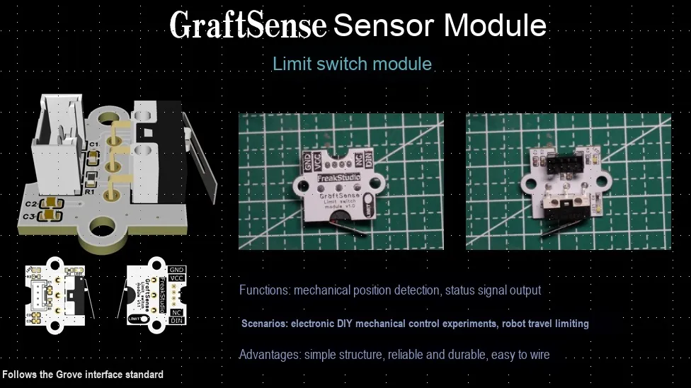
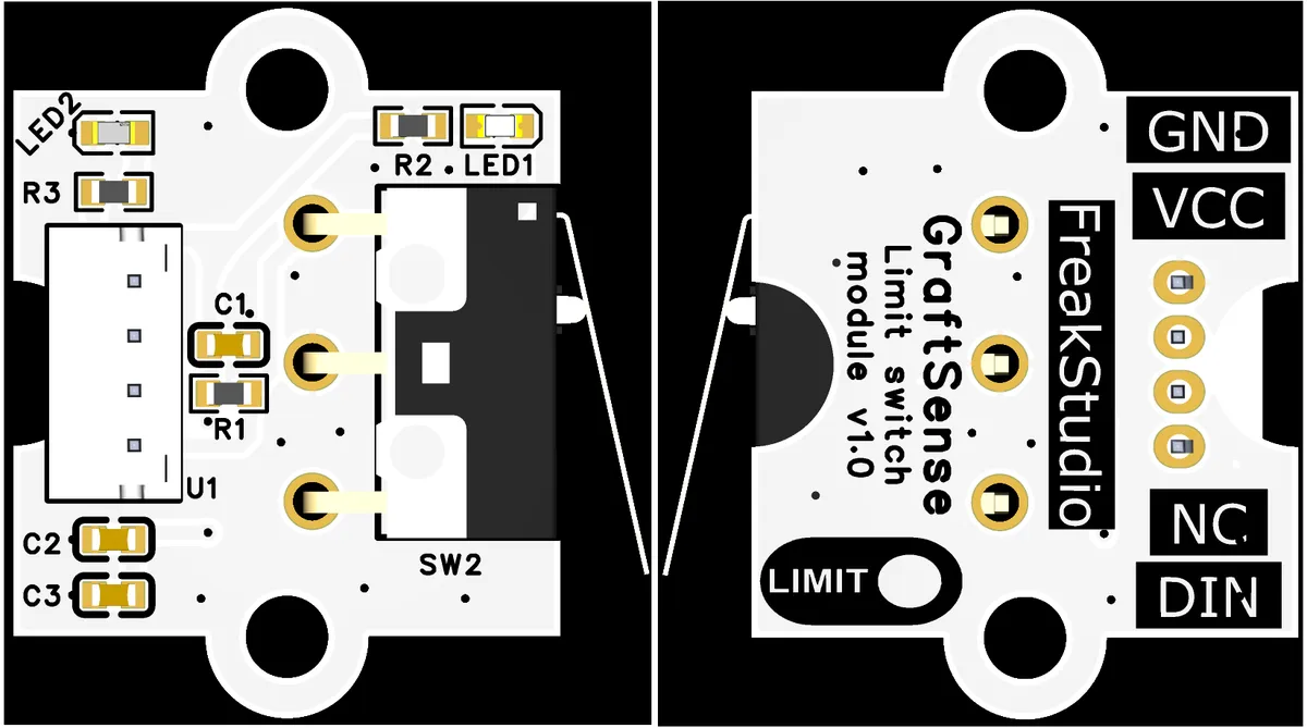
I. Module Introduction
Limit switch module that integrates limit switches, sensor interfaces, dual indicator lights and filter circuits, and connects to the system via GND, VCC, NC, and DIN interfaces. On the circuit, it uses limit switches to detect positions, and cooperates with resistors and capacitors to realize signal filtering and status indication, which can accurately feed back mechanical stroke or position trigger signals. When the external mechanical structure touches the contact of the limit switch, the module converts the mechanical displacement into an electrical signal for output through the on-off change of the electrical contact. It is suitable for position detection scenarios such as mechanical limit and stroke control of embedded systems, and provides reliable position sensing solutions for equipment.
2. Introduction to Main Chips
This module mainly relies on limit switches to achieve signal changes.
2.1 Chip Overview
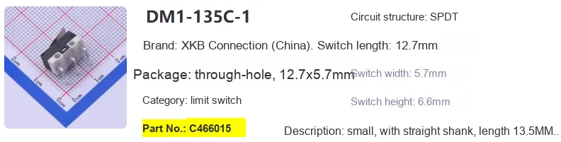
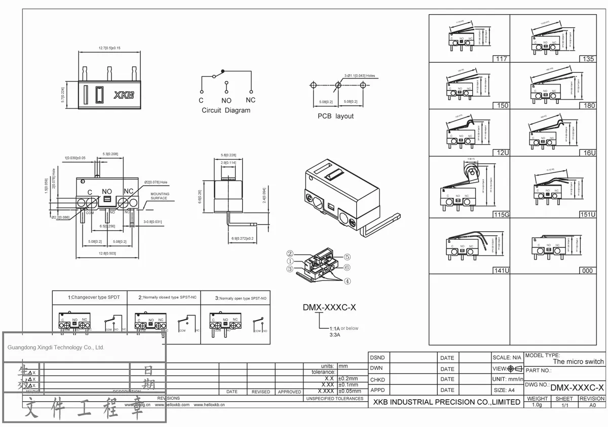
DM1-135C-1 This micro limit switch features a single-pole double-throw circuit, a plug-in package (12.7×5.7mm), a 13.5mm straight actuator, with normally open (NO), normally closed (NC) and common (C) terminals. Measuring 12.7×5.7×6.6mm, it is applicable to equipment position detection and travel control scenarios. With elaborate mechanical and circuit design, it enables precise actuation and reliable control.
2.2 Pin Definition
2.3 Functional Block Diagram
None.
2.4 Performance Parameters
None.
2.5 Reference Circuit
None.
2.6 Chip Configuration
None.
2.7 Communication Interfaces and Related Protocols
None.
2.8 PCB Routing Precautions
No special requirements.
III. Instructions for Circuit Engineering and Module Usage
3.1 Circuit Source Engineering
To obtain the circuit source project, please follow the official account [Freak Embedded]
3.2 Module Usage Instructions
The schematic diagram of this module is shown below:
SCH_Limit Switch Sensor Module_v1.0_2025-11-03.pdf 2.0 MB
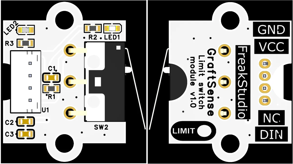
This module provides DIN input interface: the signal terminal of the module is connected to the MCU 's GPIO port, and the GPIO needs to be configured in digital input mode.
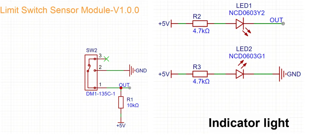
In this limit switch sensor module, when not triggered, OUT terminal outputs a high level (+ 5V), and LED1 lights up; when triggered, OUT terminal outputs a low level (GND), and LED1 turns off.
Level compatibility is required during use: if the MCU is a 3.3V system, it is recommended to add a level conversion circuit (such as using a voltage divider resistor or a level conversion chip) to prevent 5V level from being directly connected to the 3.3V GPIO to avoid hardware damage.
3.3 Application Experiment
Here, we use the GraftPort-RP2040 development board for testing, and the limit switch sensor module uses the DIO interface to communicate with the main controller.
Here, we first use the HY2.0-4P cable to connect the module to the GraftPort-RP2040 development board's DIO0 interface:
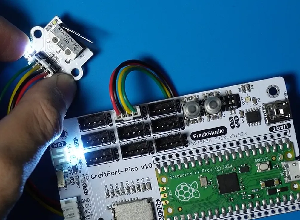
The module connections are shown in the following table:
Development Board Pins | Module Pins | Description |
Pin 6 |
| MCU upper limit switch signal input interface |
Pin 7 |
| - |
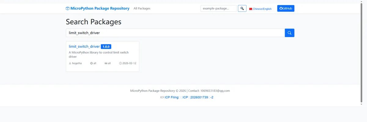
Here, we need to search for the relevant driver packages on uPyPI: https://upypi.net/zh/
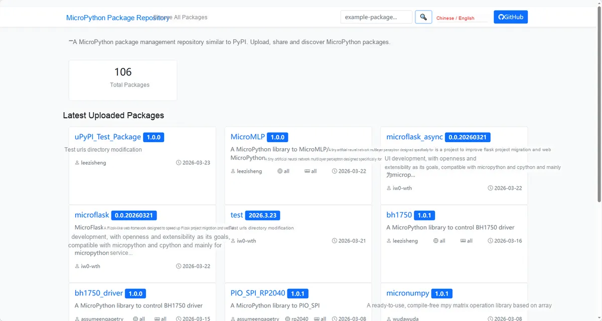
Enter limit_switch_driver to search, and the following will be displayed:
Click to copy the local installation command:
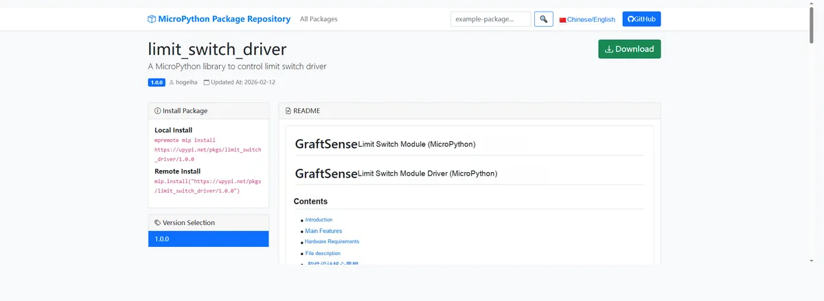
Here, we can import the module driver library code via the mip tool. Below are the usage commands for the mpremote tool:
mpremote mip install github:FreakStudioCN/GraftSense-Drivers-MicroPython/input/limit_switch_driverAfter importing the limit switch driver - MicroPython driver code, copy the following main.py code into our project:
# Python env   : MicroPython v1.23.0
# -*- coding: utf-8 -*-
# @Time    : 2025/8/25 10:35 AM
# @Author  : 缪贵成
# @File    : main.py
# @Description : Limit switch test file

# ======================================== Import Modules =========================================

import time
from limit_switch import LimitSwitch

# ======================================== Global Variables =============================================

# ======================================== Functions ==============================================

def switch_callback(state: bool):
    """
    User callback function, called when the limit switch state changes and debouncing is complete.

    Args:
        state (bool): True = released (not triggered), False = pressed (triggered)

    Notes:
        Scheduled via micropython.schedule, so it runs safely on the main thread.
    ==========================================
    User callback function, called after limit switch state change and debounce.

    Args:
        state (bool): True = released (open), False = pressed (closed)

    Notes:
        Scheduled via micropython.schedule, safe in main thread.
    """
    if state:
        print("Limit switch released (open)")
    else:
        print("Limit switch pressed (closed)")

# ======================================== Custom Classes =============================================

# ======================================== Initialization configuration ===========================================

time.sleep(3)
print("FreakStudio: Limit switch test")

# Initialize the limit switch, set the debounce interval to 50ms
switch = LimitSwitch(pin=6, callback=switch_callback, debounce_ms=50)
# Enable debounce detection
switch.enable()

# ======================================== Main Program =============================================

try:
    while True:
        state = switch.read()
        if state:
            print("Current state: released (open)")
        else:
            print("Current state: pressed (closed)")
        time.sleep(1)
except KeyboardInterrupt:
    # Stop the test
    print("Test stopped by user.")
    switch.disable()
Burn the code, open the terminal, and use the mpremote tool to connect to the main controller. The output is as follows:
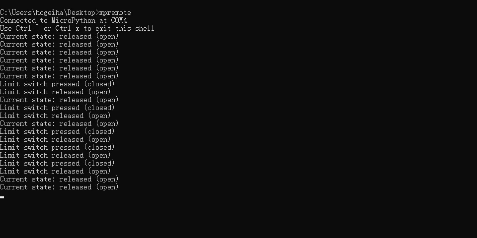
You can see that when we press the switch, the terminal will print the interrupt output:
4. Drivers
limit_switch_driver.zip 10 KB
5. BOM & Recommended Alternative Parts
None.
VI. Revision History
Document Version | Date of Modification | Modifier | Revised Content |
v1.0 | 2025-08-31 | Hou Junhan Zero Kōkō | Initialize Document |
v1.1 | 2025-11-03 | Li Zisheng | Added PCB routing precautions for Version 2.8 Revised Section 3, Instructions for Circuit Source Project and Module Usage, and added a secondary heading: 3.1 Circuit Source Engineering, 3.2 Module Usage Instructions, 3.3 Application Experiments The BOM sheet has not been finally checked, the driver has not been re-verified, and the 3.3 application experiment Not yet specified. |
v1.2 | 2025-12-29 | Li Zisheng | Added application experiments and production files |
v1.3 | 2025-12-31 | Xin Ruili | Create an open version of the document based on the internal document version v1.2. |
v1.4 | 2026-03-29 | Xin Ruili | Modified the application experiment section. |
VII. Relevant Materials
7.1 Chip Datasheet
Limit Switch.pdf 1.1 MB
7.2 Unique Icons for PCB Silk Screen