Contents
- I. Module Introduction
- II. Introduction to Major Chips
- 2.1 Chip Overview
- 2.2 Pin Definition
- 2.3 Functional Block Diagram
- 2.4 Performance Parameters
- 2.5 Reference Circuit
- 2.6 Chip Configuration
- 2.7 Communication Interfaces and Related Protocols
- 2.8 PCB Routing Precautions
- III. Circuit Engineering
- 3.1 Circuit Source Engineering
- 3.2 Module Usage Instructions
- 3.3 Application Experiment
- IV. Drivers
- 5. BOM & Recommended Alternative Parts
- VI. Revision History
- VII. Relevant Materials
- 7.1 Chip Datasheet
- 7.2 Unique Icons for PCB Silkscreen
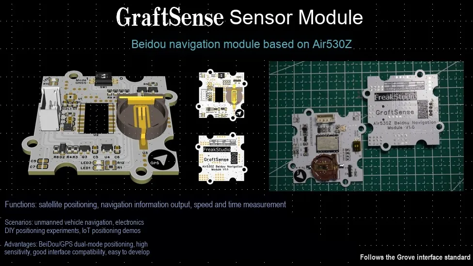
I. Module Introduction
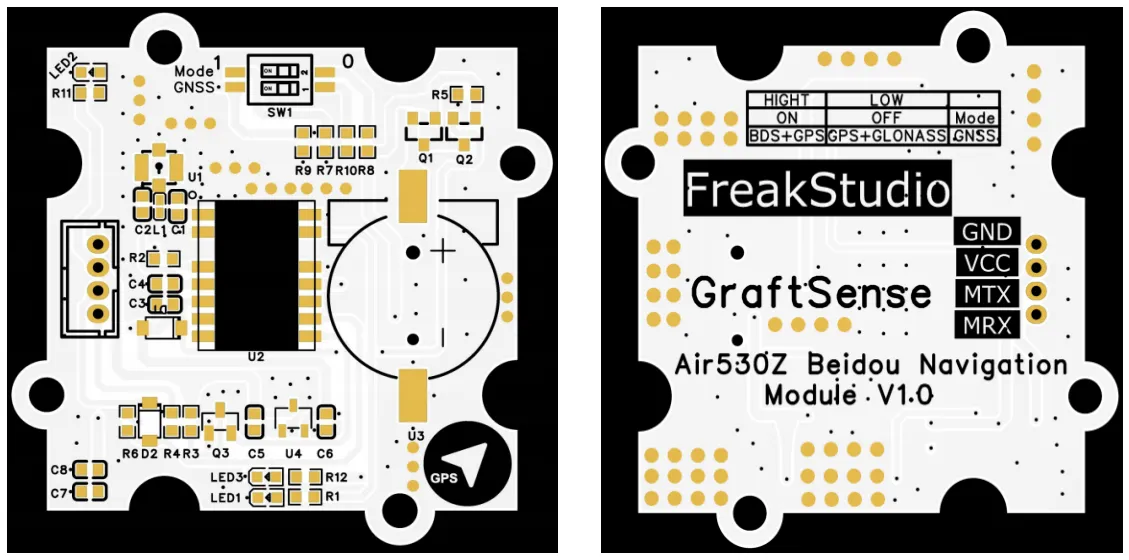
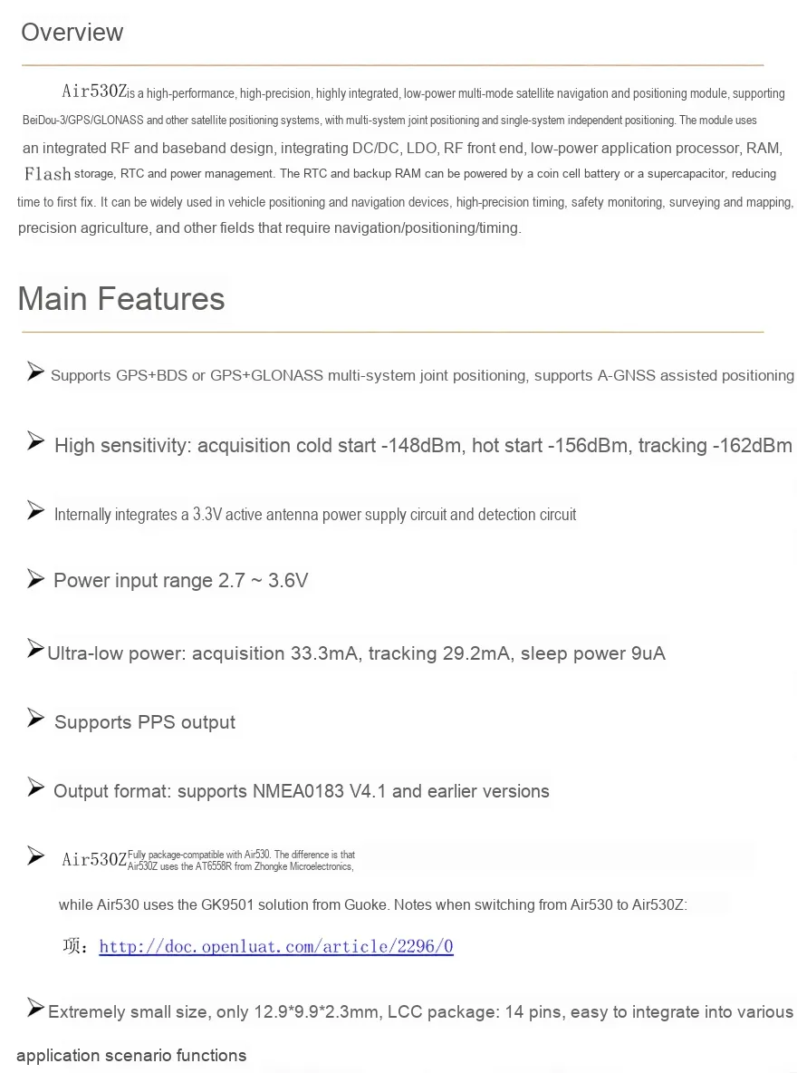
The Beidou navigation module based on Air530Z is a high-performance, high-precision navigation component that adopts the Air530Z navigation module design, supports multi-system joint positioning of GPS+ BDS or GPS+ GLONASS, and also features the A-GNSS assisted positioning function.The module's input power supply is 5V, and internally through the DC-DC 5V to 3.3V circuit and level conversion circuit, it realizes UART communication with the controller (compatible with 5V and 3.3V levels). It is equipped with a dual power supply switching circuit, a DIP switch circuit, a MCU interface, etc. , supports hot-start positioning (the cold start time is reduced from 32s to less than 1s), and features ultra-low power consumption (33.3mA during acquisition, 29.2mA during tracking, and 9uA during sleep).It is applicable to scenarios that have requirements for navigation and positioning accuracy and power consumption, such as vehicle-mounted positioning, navigation devices, high-precision time synchronization, and safety monitoring, providing stable and reliable satellite navigation and positioning services for devices.
II. Introduction to Major Chips
This module adopts the Air530Z chip.
2.1 Chip Overview
2.2 Pin Definition
2.3 Functional Block Diagram
None.
2.4 Performance Parameters
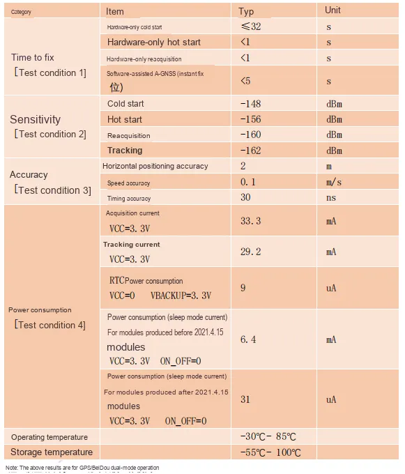
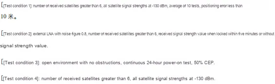
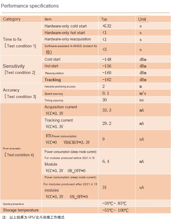
Some parameters in the table are shown as follows:
- Positioning time:
- Pure hardware cold start ≤ 32s (the maximum time to first positioning after the module is completely powered off),
- Pure hardware warm start < 1s(fast start time when the last positioning was less than 2 hours ago),
- Pure hardware re-acquisition < 1s(time to re-lock onto satellites after a brief signal loss),
- Software-assisted
A-GNSS(second-level positioning) <5s(pre-acquires satellite ephemeris and time information via the mobile network to achieve "second-level positioning").
- Sensitivity:
- Cold start - 148dBm (the minimum power level for successful satellite signal acquisition),
- Warm start - 156 dBm (the minimum signal strength detectable in warm start state),
- Re-acquisition: -160dBm (sensitivity upon signal recovery),
- Tracking: -162 dBm (the minimum signal strength required for continuous satellite locking).
- Precision:
- Horizontal positioning accuracy: 2m (in an open environment, the error of the horizontal distance between the positioning point and the actual position is ≤ 2m),
- Speed accuracy: 0.1m/s (the error in measuring the speed of a moving object shall not exceed 0.1m/s),
- Timing accuracy: 30ns (the deviation between the provided timestamp and GPS standard time is less than 30 nanoseconds).
- Power Consumption:
- Captured current value (
VCC= 3.3V): 33.3mA (operating current during satellite acquisition and positioning), - Tracking current value (
VCC= 3.3V): 29.2mA (current maintained for tracking after stable positioning); RTCpower consumption (VCC= 0, VBACKUP= 3.3V): 9uA; for modules produced before April 15,2021, the current in sleep mode is 6.4mA (VCC= 3.3V,ON_OFF= 0), and for modules produced after that date, the current is 31uA (VCC= 3.3V, ON_OFF= 0).- Operating Temperature: -30℃ to 85℃, Storage Temperature: -55℃ to 100℃.
- Captured current value (
2.5 Reference Circuit
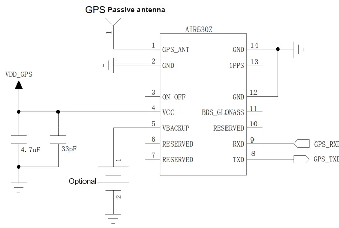
Air530Z A brief introduction to the reference circuit of the multi-mode satellite positioning module is as follows: Positioning signals are accessed via a GPS passive antenna;VDD_GPS supplies power to the module through a filter capacitor, and VBACKUP serves as an optional backup power supply. The module can be started and stopped via the ON_OFF pin, communicates with the main controller through the RXD / TXD serial port, and outputs a 1PPS second pulse at the same time. It also supports BDS / GLONASS multi-mode positioning, making it a compact satellite positioning hardware solution.
2.6 Chip Configuration
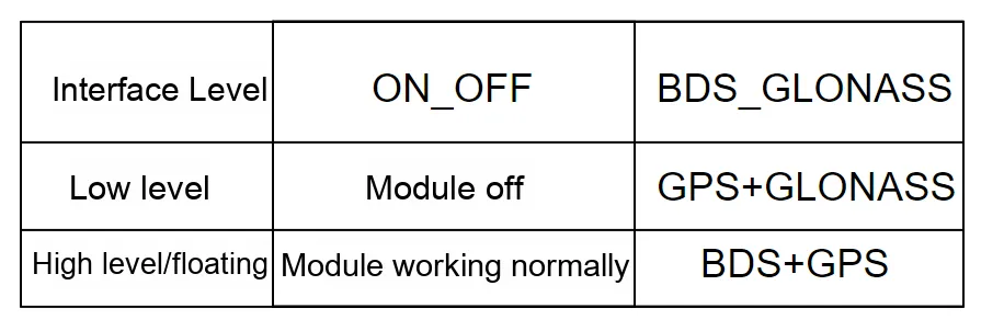
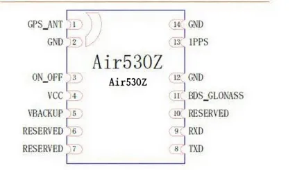
This module uses two switches to control the interface level: ON_OFF controls the operation of the module, while BDS_GLONASS is used to select the operating mode of the module.
2.7 Communication Interfaces and Related Protocols
None.
2.8 PCB Routing Precautions
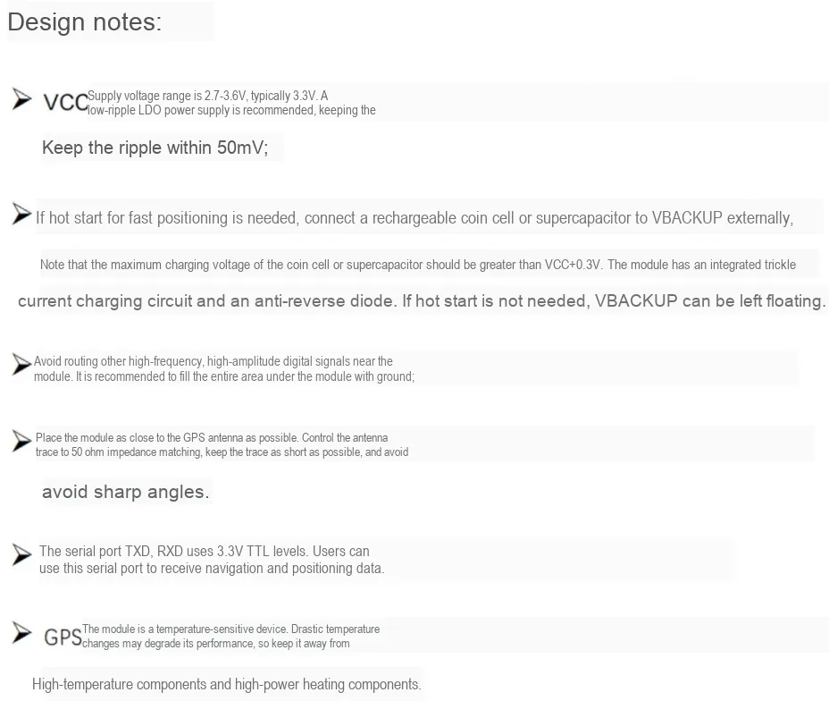
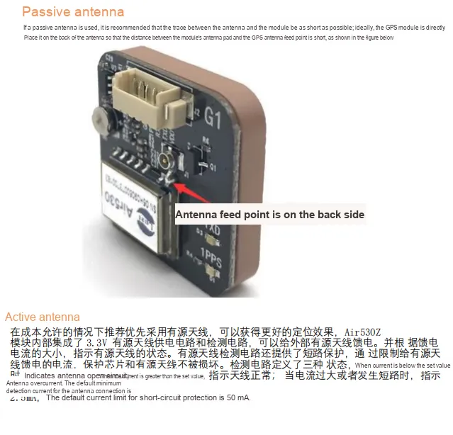
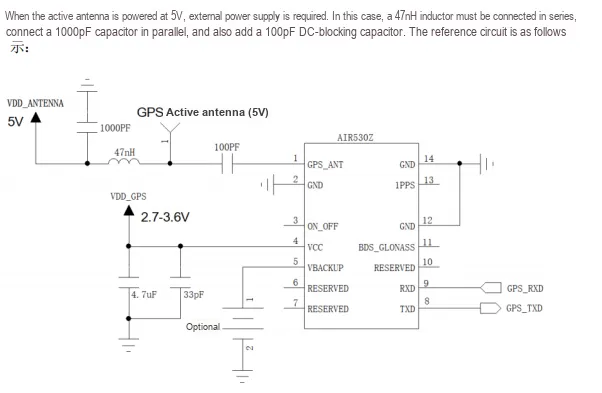
III. Circuit Engineering
3.1 Circuit Source Engineering
To obtain the source project of the circuit, please follow the official account [Freak Embedded]
3.2 Module Usage Instructions
SCH_Schematic1_BeiDou Navigation Module Based on Air530Z-V1.0.0_2025-11-10.pdf 2.2 MB
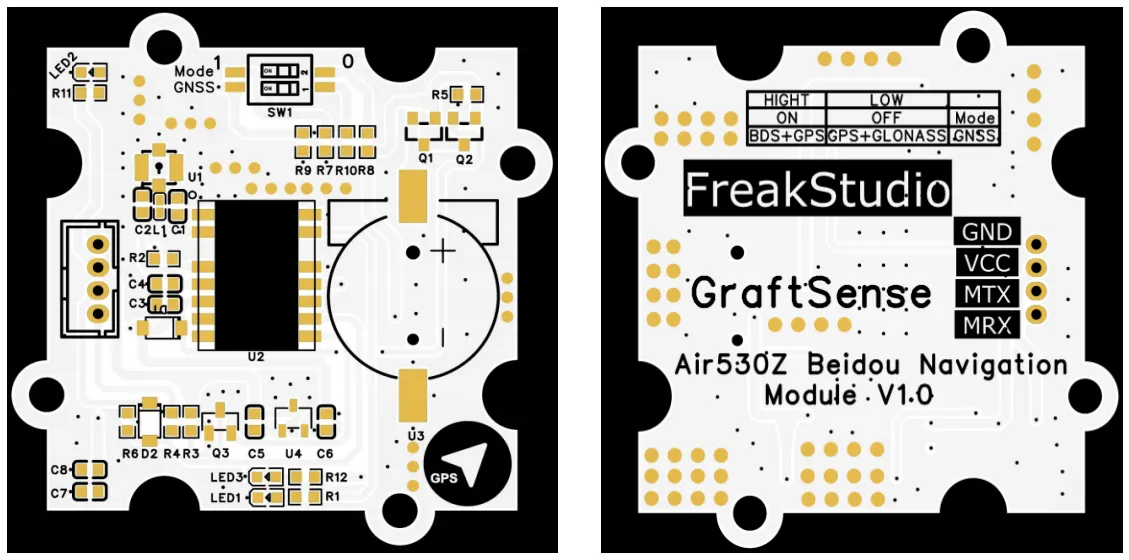
In this module, MRX (corresponding to the UART RXD pin of the MCU) is physically connected to the Air530Z ’s R1OUT pin, and MTX (corresponding to the UART TXD pin of the MCU) is physically connected to the Air530Z ’s T1IN pin. This is because UART serial communication follows the "crossed transmit-receive" rule — the transmit terminal (TX) of one communication party must be connected to the receive terminal (RX) of the other party; this design ensures correct bidirectional transmission of UART serial data between the MCU and Air530Z.
Of particular note is that when using this module, MRX is directly connected to the RXD pin of the MCU's serial port, and MTX is directly connected to the TXD pin of the MCU's serial port; be sure not to cross-connect them.

As shown in the figure, this module uses two switches to control the interface level, where ON_OFF controls the operation of the module, and BDS_GLONASS is used to select the working mode of the module. It is worth noting that the functions corresponding to the DIP switches of the GPS module can only take effect after the power is turned off and then turned on again, and cannot be switched during operation.
It should be noted that when using this module, we must place it in an open outdoor area to correctly read the relevant latitude and longitude information.
3.3 Application Experiment
Here, we use the GraftPort-RP2040 development board for testing, and connect the Beidou navigation module based on Air530Z to communicate with the main controller via the UART interface.
Here, we first use the HY2.0-4P cable to connect the module to the GraftPort-RP2040 development board's UART0 interface:
The module connections are shown in the following table:
Development Board Pins | Module Pins | Description |
Pin 16 |
|
|
Pin 17 |
|
|
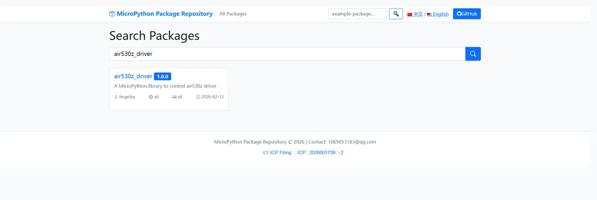
Here, we need to search for the relevant driver packages on uPyPI: https://upypi.net/zh/

Enter air530z_driver to search, and the following will be displayed:
Click to copy the local installation command:
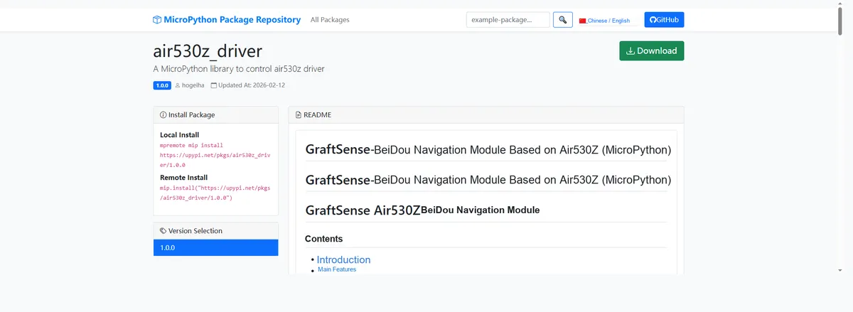
Here, we can import the module driver library code via the mip tool. Below are the usage commands for the mpremote tool:
mpremote mip install github:FreakStudioCN/GraftSense-Drivers-MicroPython/sensors/air530z_driverImport the Beidou navigation module based on Air530Z - MicroPython driver code, then copy the following main.py code into our project:
# Python env   : MicroPython v1.23.0
# -*- coding: utf-8 -*-
# @Time    : 2025/9/5 10:11 PM
# @Author  : ben0i0d
# @File    : main.py
# @Description : air530z test file

# ======================================== Import Modules =========================================

import time
from machine import UART, Pin
from air530z import Air530Z, NMEASender
from nemapar import NMEAParser

# ======================================== Global Variables ============================================

# ======================================== Functions ============================================

# ======================================== Custom Classes =============================================

# ======================================== Initialization configuration ===========================================

# Power-on delay of 3 s
time.sleep(3)
print("FreakStudio: air530z test")

# Initialize UART communication (adjust TX/RX according to the actual hardware wiring)
uart0 = UART(0, baudrate=9600, tx=Pin(16), rx=Pin(17))
# Create an Air530Z instance
gps = Air530Z(uart0)

# ========================================  Main Program  ===========================================

while True:
    try:
        gps_data = gps.read()
    except Exception as e:
        print("Error reading GPS data:", e)

    if gps_data:
        print("=" * 40)
        print("GPS_DATA")
        print("=" * 40)

        # Coordinates
        # Longitude
        print(f"longitude: {gps_data['longitude']}°")
        # Latitude
        print(f"latitude: {gps_data['latitude']}°")

        # Altitude
        print(f"altitude: {gps_data['altitude']}")
        # Time
        if gps_data['timestamp'] is None:
            print("time:None")
        else:
            ts = gps_data['timestamp']
            print(f"time: {ts['hour']:02d}:{ts['minute']:02d}:{ts['second']:02d}")

        # Satellites
        print(f"satellites: {gps_data['satellites']}")
        print("=" * 40)
    time.sleep(1)
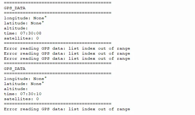
When flashing the code, the terminal continuously outputs the following content:
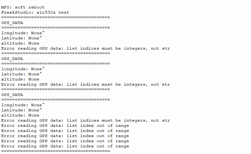
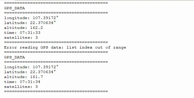
After the module runs, it will proceed in three sequential phases: time synchronization, satellite locking, and successful positioning. The output results corresponding to each phase are shown in the figure below.
The module has just started and has not yet output synchronized time.
When the time synchronization succeeds, the following content will be output, indicating that the time has been output correctly.
It will then attempt to communicate with satellites, output the number of positioning satellites, and try to perform positioning.
(There are already three satellites and positioning has been completed successfully; if there are insufficient satellites, the latitude and longitude will not be output.)
The following are the correctly parsed original data
$GNGGA,073130.993,2222.23809,N,10723.50332,E,1,09,2.8,162.6,M,-25.9,M,,*64
$GNGLL,2222.23809,N,10723.50332,E,073130.993,A,A*42
$GNGSA,A,3,01,02,04,09,195,199,,,,,,,5.5,2.8,4.8,1*35
$GNGSA,A,3,06,16,30,,,,,,,,,,5.5,2.8,4.8,4*30
$GPGSV,2,1,07,01,34,161,36,02,54,118,43,04,24,190,27,09,35,228,31,0*62
$GPGSV,2,2,07,194,,,17,195,43,113,29,199,56,137,32,0*5C
$BDGSV,2,1,05,03,,,35,06,77,071,37,16,75,078,37,30,72,181,37,0*47
$BDGSV,2,2,05,59,,,31,0*7F
$GNRMC,073130.993,A,2222.23809,N,10723.50332,E,0.09,0.00,231225,,,A,V*03
$GNVTG,0.00,T,,M,0.09,N,0.17,K,A*2C
$GNZDA,073130.993,23,12,2025,00,00*4A
$GPTXT,01,01,01,ANTENNA OK*35
Enter Latitude and Longitude Conversion Baidu Latitude and Longitude Map Query
- Latitude (North latitude)
- Original value: 2222.24333 N
- Degree-minute-second conversion: 22° + 22.24333′ = 22°22′14.6″(22.24333 minutes = 22 minutes + 0.24333×60 seconds ≈ 22 minutes 14.6 seconds);
- Decimal degrees: 22 + 22.24333 ÷ 60 ≈ 22.3707°.
- Longitude (East)
- Original value: 10723.49811 E
- Degree-Minute-Second Conversion: 107° + 23.49811′ = 107°23′29.9″(23.49811 minutes = 23 minutes + 0.49811 × 60 seconds ≈ 23 minutes 29.9 seconds);
- Decimal degrees: 107 + 23.49811÷60 ≈ 107.3916°.
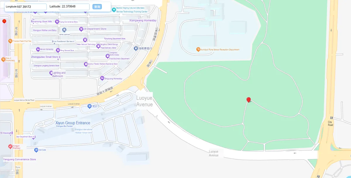
Correct Parsing
IV. Drivers
air530z_driver.zip 14 KB
5. BOM & Recommended Alternative Parts
None.
VI. Revision History
Document Version | Date of Revision | Modifier | Modified Content |
v1.0 | 2025-11-10 | Ling Gaoxing | Initialize the document |
v1.1 | 2025-12-29 | Li Zisheng | Added application experiments and production files |
v1.2 | 2025-12-31 | Xin Ruili | Create an open version of the document based on the internal document version v1.1. |
v1.3 | 2026-03-29 | Xin Ruili | Modified the application experiment section |
VII. Relevant Materials
Schematic Diagram of Air530Z
Grove - GPS (Air530)_v1.0_SCH_191111.pdf 28 KB
Original Components and Packaging
Grove - GPS (Air530)_v1.0_191111.brd 161 KB
Grove - GPS (Air530)_v1.0_191111.sch 885 KB
Instructions for Use
20201024170240169_AGPS User Guide.zip 727 KB
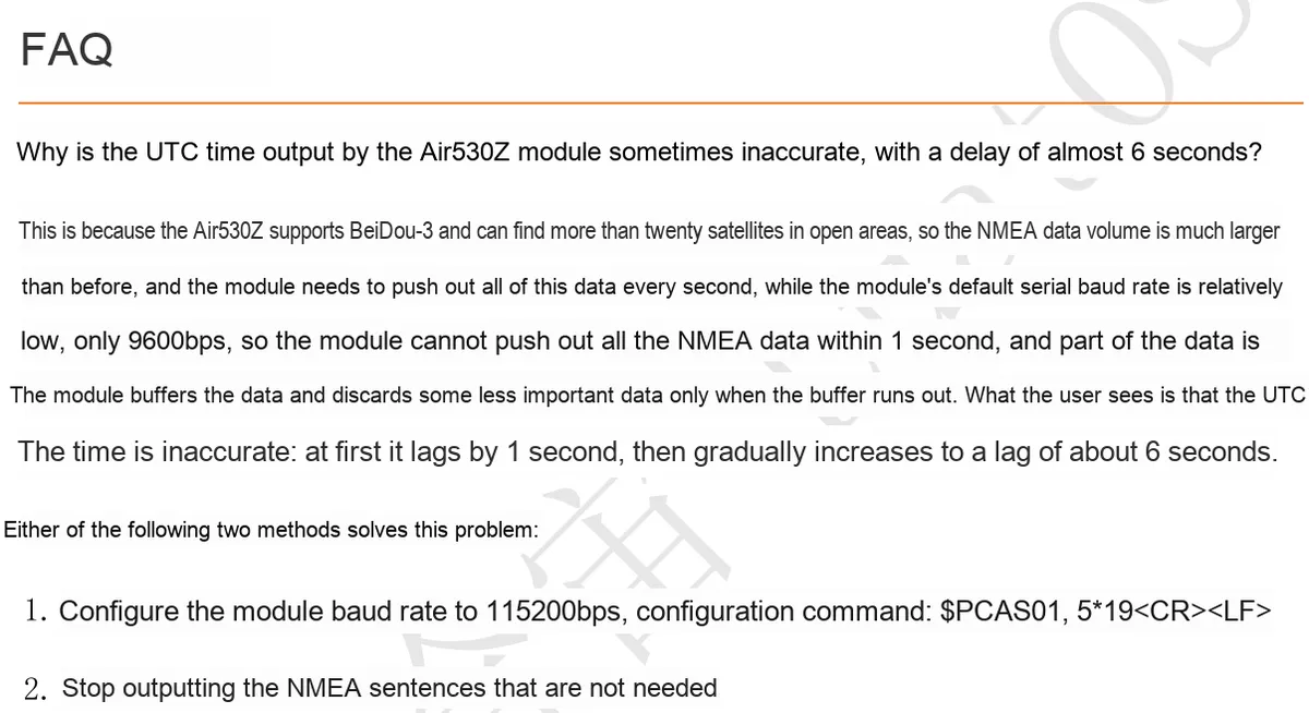
FAQ
7.1 Chip Datasheet
20210301115201307_CASIC Multi-Mode Satellite Navigation Receiver Protocol Specification-20210301.pdf 2.9 MB
20211221160333351_Air530Z Positioning Module User Manual V1.4.pdf 1.3 MB
7.2 Unique Icons for PCB Silkscreen