Contents
- I. Module Introduction
- II. Introduction to Major Chips
- 2.1 Chip Overview
- 2.2 Pin Definition
- 2.3 Functional Block Diagram
- 2.4 Performance Parameters
- 2.5 Reference Circuit
- 2.6 Chip Configuration
- 2.7 Communication Interfaces and Related Protocols
- 2.8 PCB Routing Precautions
- III. Instructions for Circuit Engineering and Module Usage
- 3.1 Circuit Source Engineering
- 3.2 Module Usage Instructions
- 3.3 Application Experiment
- IV. Drivers
- 5. BOM & Recommended Alternative Parts
- VI. Revision History
- VII. Relevant Materials
- 7.1 Chip Datasheet
- 7.2 Unique Icons for PCB Silkscreen
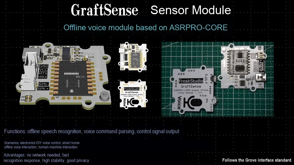
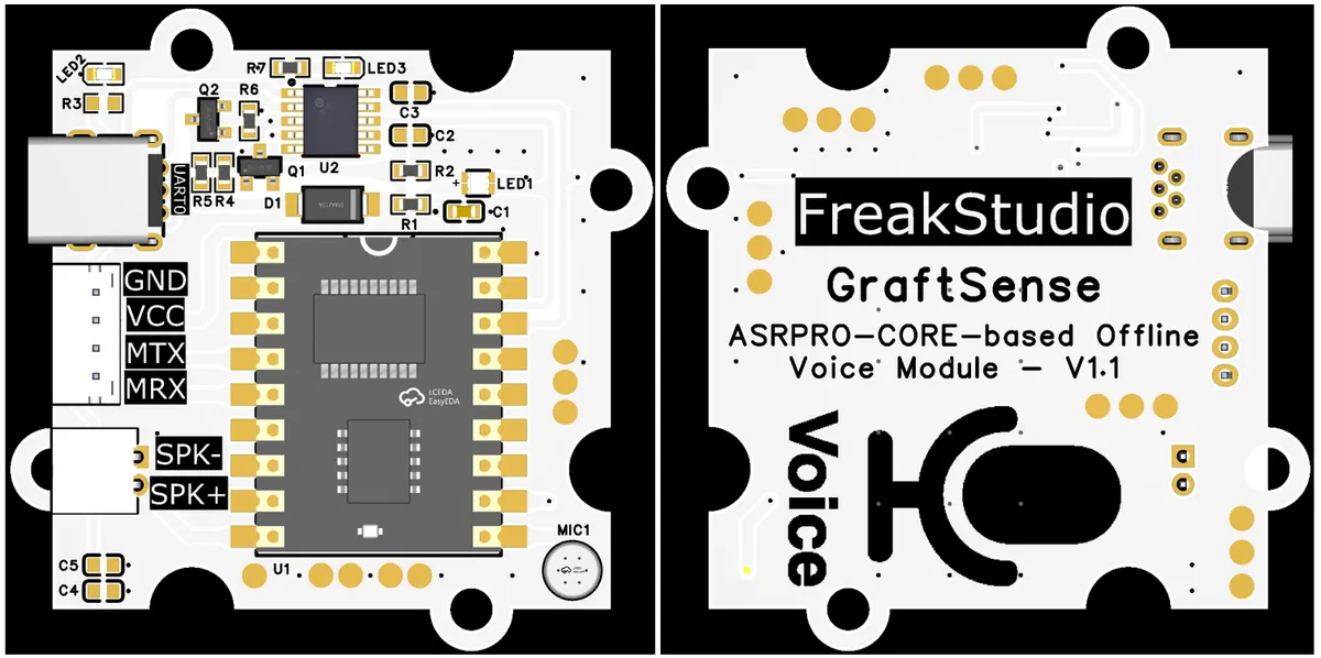
I. Module Introduction
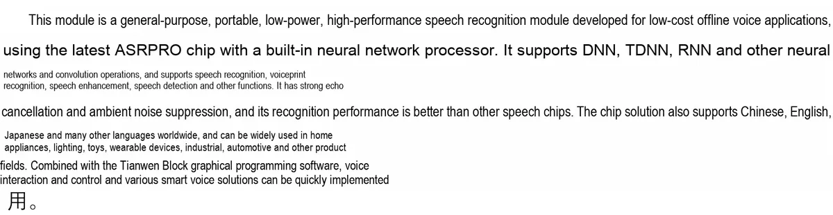
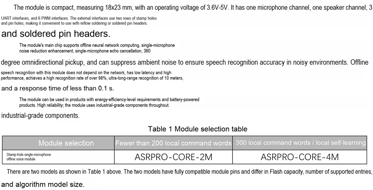
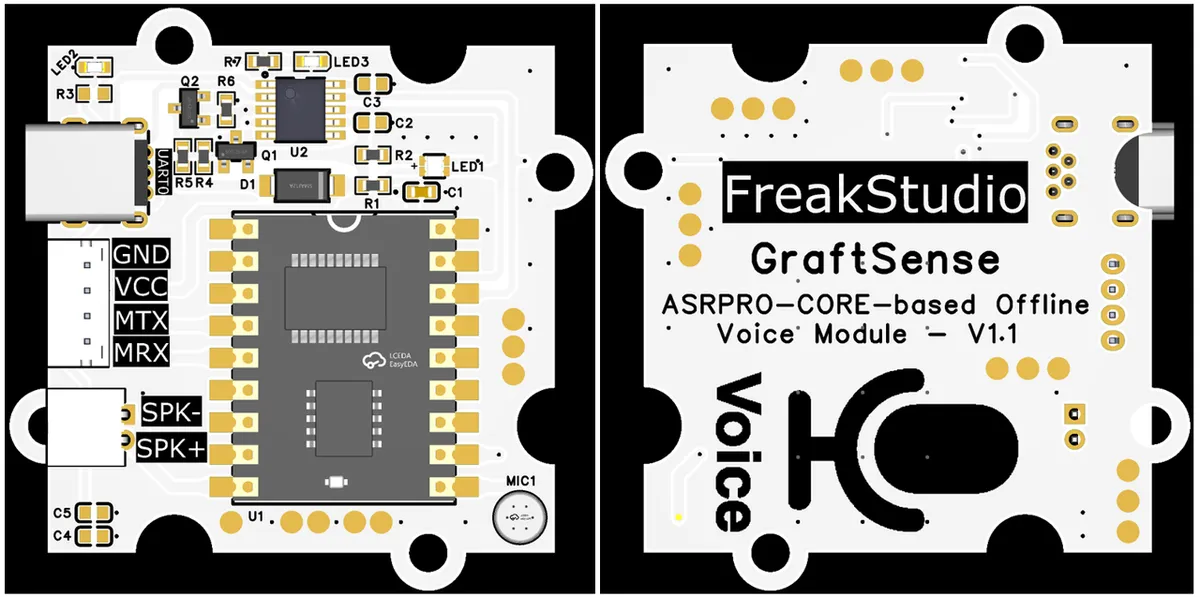
The offline voice module based on ASRPRO-CORE is an offline voice module built on the ASRPRO-CORE chip. It integrates a microphone, speaker interface, and UART communication interface (the module can act as a coprocessor for speech recognition, communicating with the main controller via the serial port), and comes with an onboard automatic download circuit. Adopting industrial-grade components, it supports multi-language offline speech recognition including Chinese and English, voiceprint recognition and ambient noise suppression, with a speech recognition rate exceeding 98% and a response latency of less than 0.1 seconds. Operating at a voltage of 3.6V-5V, it is applicable to scenarios such as home appliances, industrial equipment and wearable devices, and can be paired with graphical programming software to quickly implement intelligent voice interaction solutions.
II. Introduction to Major Chips
This module is designed based on ASRPRO-CORE core board.
2.1 Chip Overview
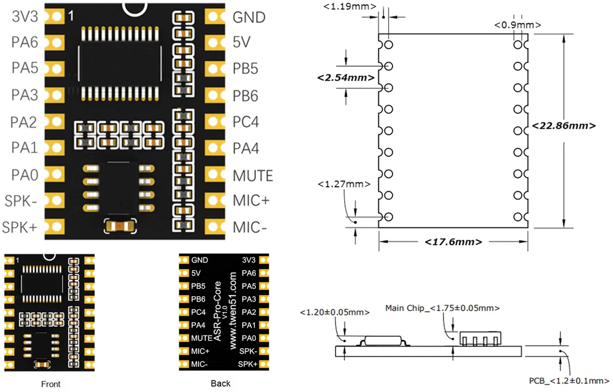
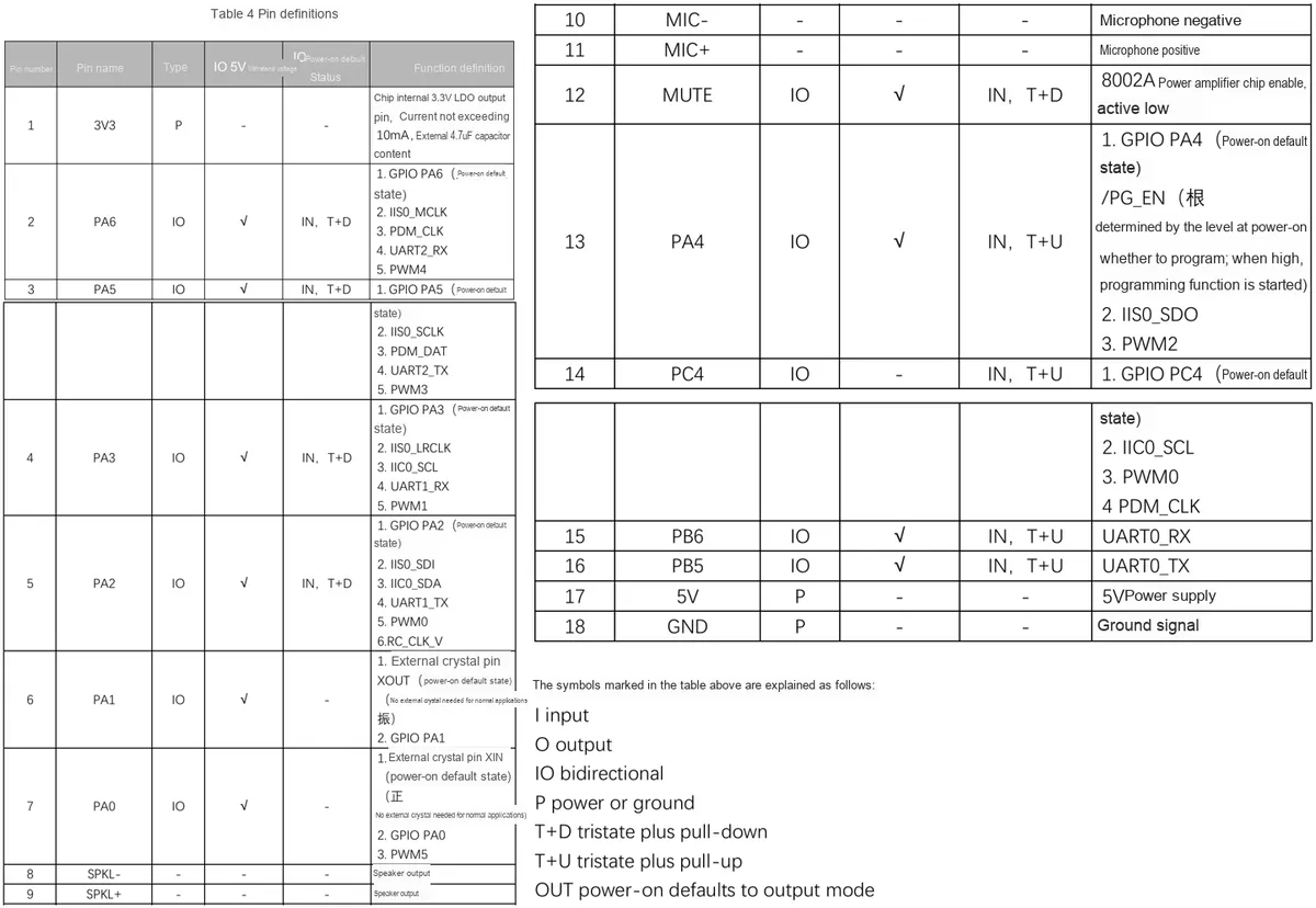
2.2 Pin Definition
2.3 Functional Block Diagram
None.
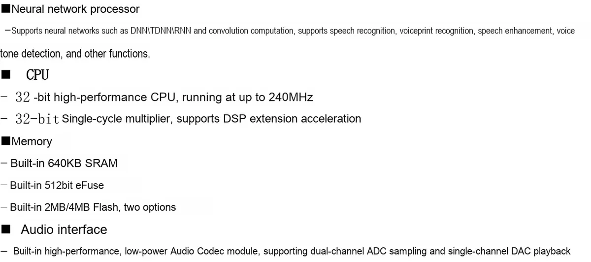
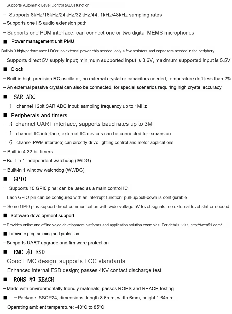
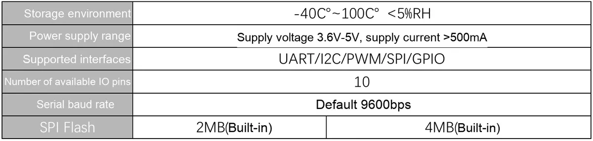
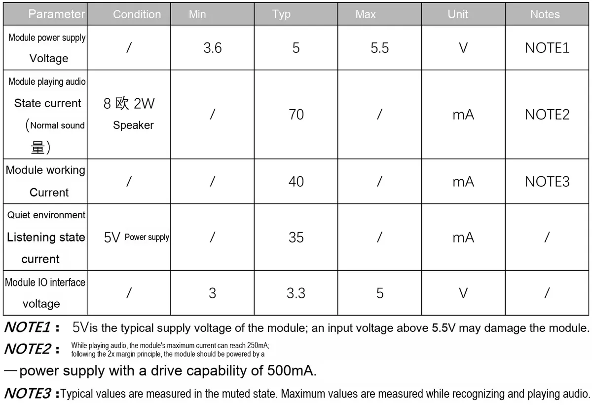
2.4 Performance Parameters

2.5 Reference Circuit
2.6 Chip Configuration
None.
2.7 Communication Interfaces and Related Protocols
None.
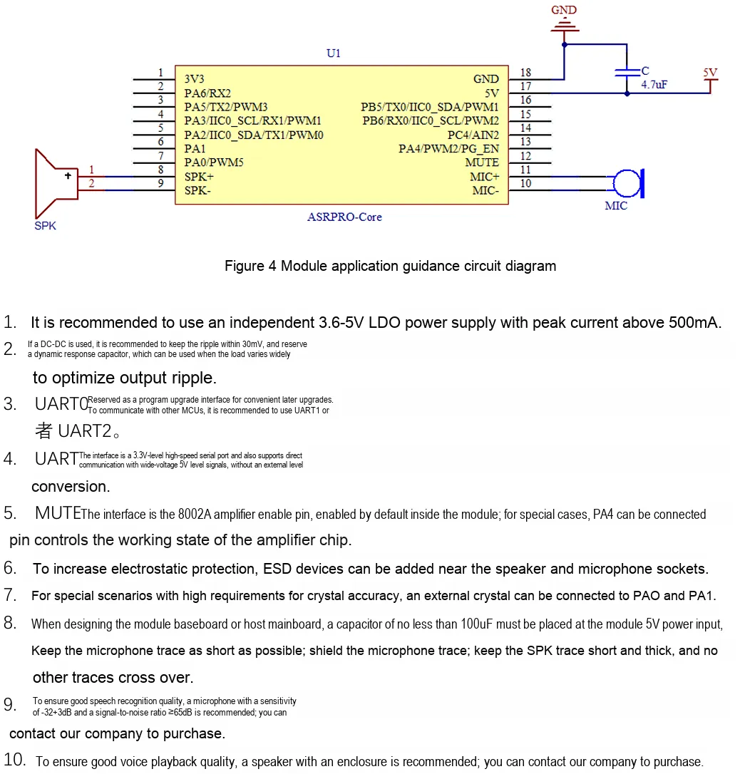
2.8 PCB Routing Precautions
III. Instructions for Circuit Engineering and Module Usage
3.1 Circuit Source Engineering
To obtain the source project of the circuit, please follow the official account [Freak Embedded]
3.2 Module Usage Instructions
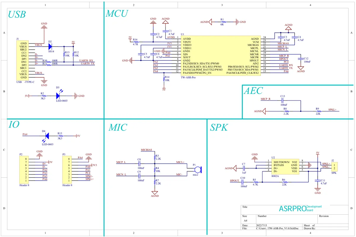
The schematic diagram of this module is shown below:
SCH_ASRPRO-CORE-Based Offline Voice Module_v1.1_2025-11-23.pdf 2.4 MB
This module provides a serial port UART interface MRX and MTX: here M stands for master, which means the MCU 's RX corresponds to the module' s TX.
This module can function as a speech recognition coprocessor, which performs data interaction with the main control device via a serial port, and provides intelligent speech capability support for the system in the form of serial port commands by integrating functions such as offline speech recognition and voiceprint recognition.
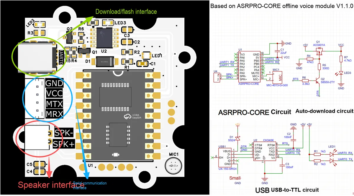
For the onboard automatic download circuit, pay attention to the operation sequence during programming: supply power to the UART interface first, then connect the MiniUSB data cable to the USB download port, so as to ensure the normal progress of program programming.
For the speaker interface, it is recommended to use a speaker with a specification of 8 ohms and 2W to ensure that the sound quality and power of the voice output are matched, so as to achieve a clear and stable voice playback effect.
3.3 Application Experiment
Here, we use the GraftPort-RP2040 development board for testing, and the ASRPRO-CORE-based offline voice module uses the UART interface to communicate with the main controller.
Here, we first use the HY2.0-4P connection cable to connect the module to the GraftPort-RP2040 development board's UART0 interface:
The module connections are shown in the following table:
Development Board Pins | Module Pins | Description |
Pin 16 |
|
|
Pin 17 |
|
|
- |
| Speaker interface, connect to a speaker |
Import the offline voice module based on ASRPRO-CORE - MicroPython driver code, then open the pico_code folder and copy the following main.py code into our project:
# Python env   : MicroPython v1.23.0
# -*- coding: utf-8 -*-
# @Time    : 2025/09/08 10:00
# @Author  : 侯钧瀚
# @File    : mian.py
# @Description : Voice module serial port on/off onboard LED example for MicroPython

# ======================================== Import Modules =========================================

import machine
import time

# ======================================== Global Variables ============================================

# ======================================== Functions ============================================

# Blink function (blink 2 times, 0.5 s on/off each time)
def led_blink():
    """
    LED blink.
    ===========================
    LED blink.
    """
    # Blink 2 times (the count can be changed)
    for _ in range(2):
        led.value(1)
        time.sleep(0.5)
        led.value(0)
        time.sleep(0.5)


# ======================================== Custom Classes ============================================

# ======================================== Initialization ==========================================

# Power-on delay of 3 s
time.sleep(3)
# Print debug message
print("FreakStudio: Use ASRPRO UART to control onboard LED.")

# Initialize the onboard LED (GPIO25, output mode)
led = machine.Pin(25, machine.Pin.OUT)

# Initialize the serial port: baud rate 115200, TX=GPIO16, RX=GPIO17 (Pico default hardware UART0)
uart = machine.UART(0, baudrate=115200, tx=machine.Pin(16), rx=machine.Pin(17))

# ========================================  Main Program  ============================================

# Main loop: continuously listen for serial data
while True:
    # Check whether serial data has been received
    if uart.any():
        # Read 1 byte of data (key point: read only 1 byte to match 0x01/0x02/0x03)
        data = uart.read(1)
        # Make sure the data was read successfully
        if data is not None:
            # Convert the byte data to decimal (0x01→1, 0x02→2, 0x03→3)
            cmd = ord(data)
            # Perform the corresponding action according to the command
            # Received 0x01 → blink
            if cmd == 0x01:
                print("Received command 0x01, LED blinking")
                led_blink()
            # Received 0x02 → turn off
            elif cmd == 0x02:
                print("Received command 0x02, LED off")
                led.value(0)
            # Received 0x03 → turn on
            elif cmd == 0x03:
                print("Received command 0x03, LED turned on")
                led.value(1)
            # Other commands: report invalid
            else:
                print(f"Received invalid command: 0x{cmd:02X}, ignoring")
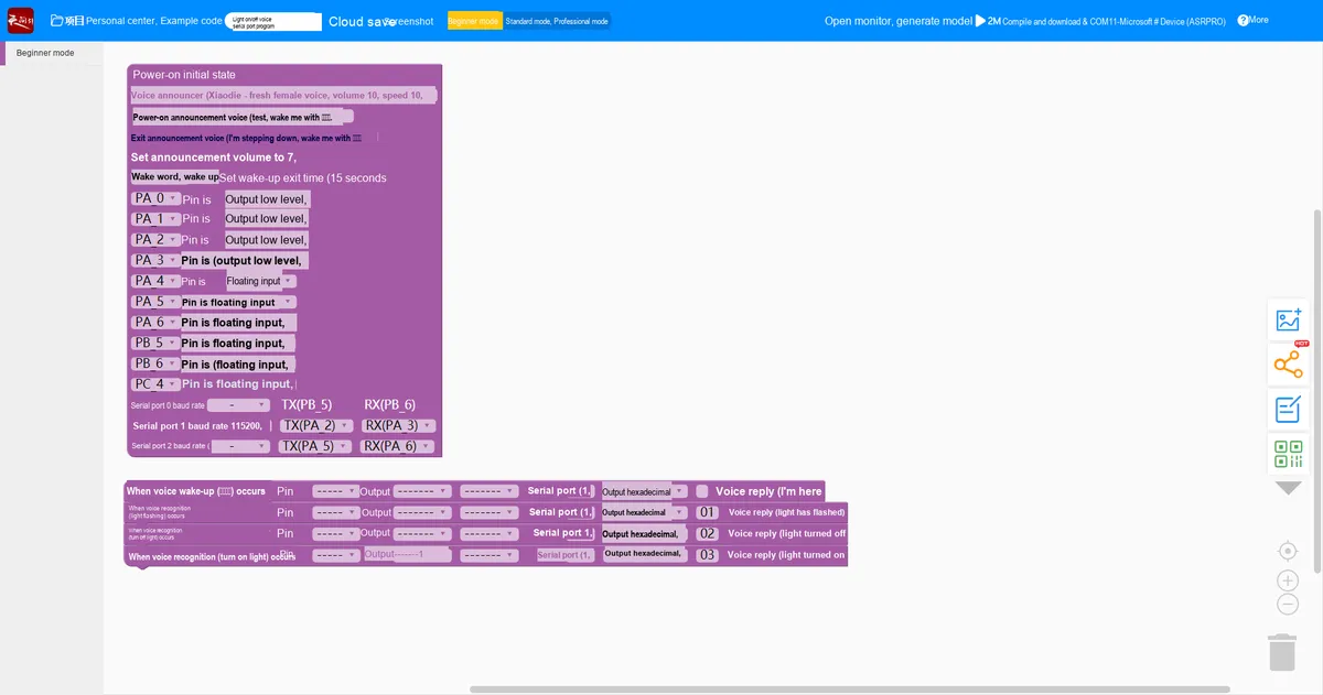
Voice Serial Port Programming for Light Switch Control: http://www.twen51.com/new/twen51/art_show.php? id= 230 (Software Download Link)
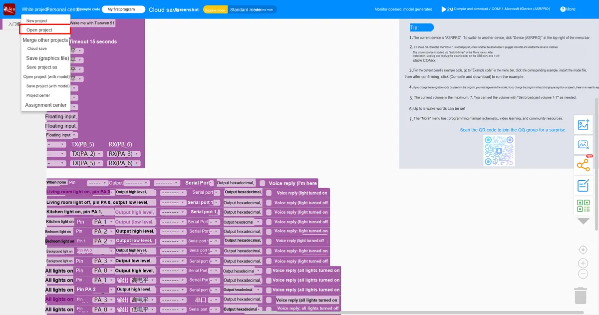
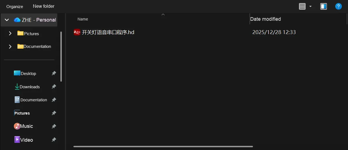
After downloading, open Tianwen 51, click "Project" in the upper left corner, select "Open Project", and choose the asrpro_code folder, then select the switch light voice serial port program inside to perform programming.
Program the following:
Burn the code, open a terminal, and use the mpremote tool to connect to the main controller; the output is as follows:
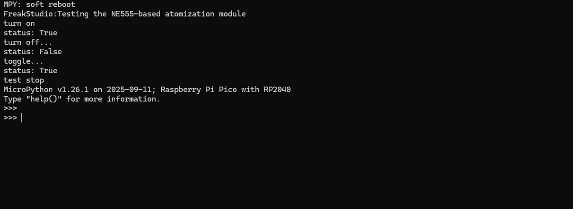
It can be seen that it can emit light sequentially in accordance with the instructions in the code.
IV. Drivers
asrpro_core_test.zip 3 KB
5. BOM & Recommended Alternative Parts
None.
VI. Revision History
Document Version | Date of Revision | Modifier | Modified Content |
v1.0 | 2025-11-23 | Li Zisheng | Initialize the document The BOM sheet has not been finally checked, the driver has not been re-verified, and the 3.3 application experiment Not yet specified. |
v1.1 | 2025-12-29 | Li Zisheng | Added application experiments and production files |
v1.2 | 2025-12-31 | Xin Ruili | Create an open version of the document based on the internal document version v1.1. |
VII. Relevant Materials
7.1 Chip Datasheet
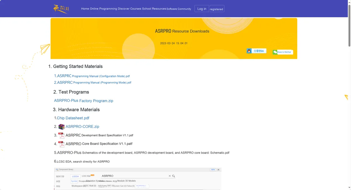
Relevant resource links are available at: https://www.twen51.com/new/twen51/learnSource.php? id= 68
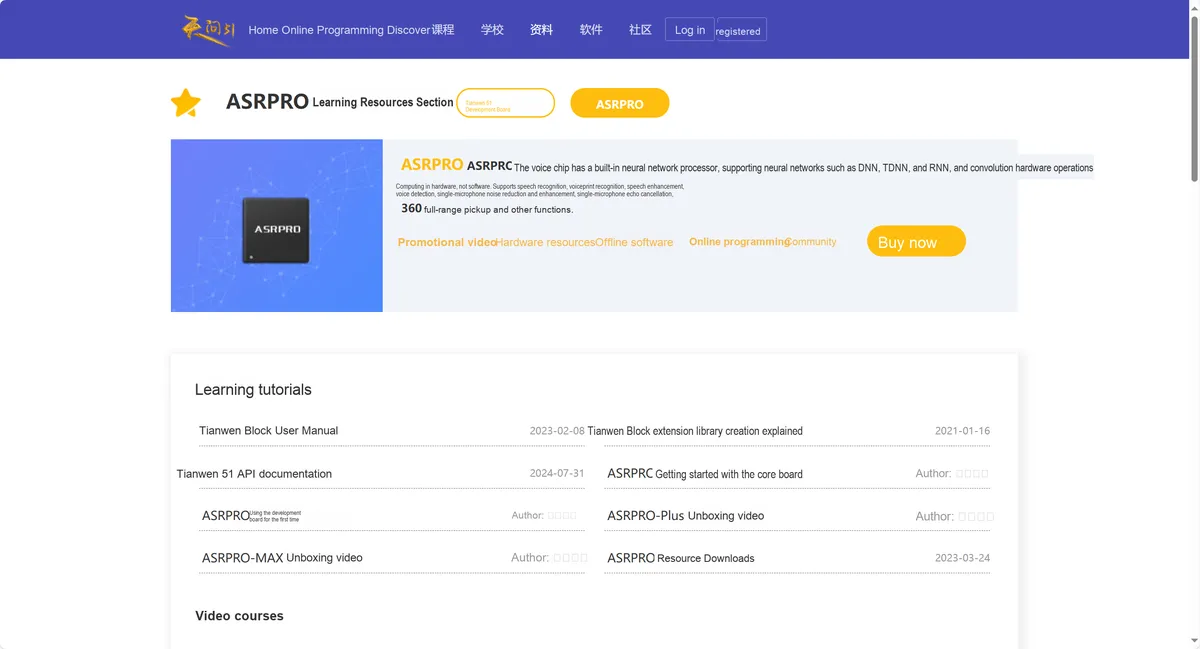
About the software IDE, you can refer to the following link for usage instructions: https://www.twen51.com/new/twen51/learning_show.php? id= 559
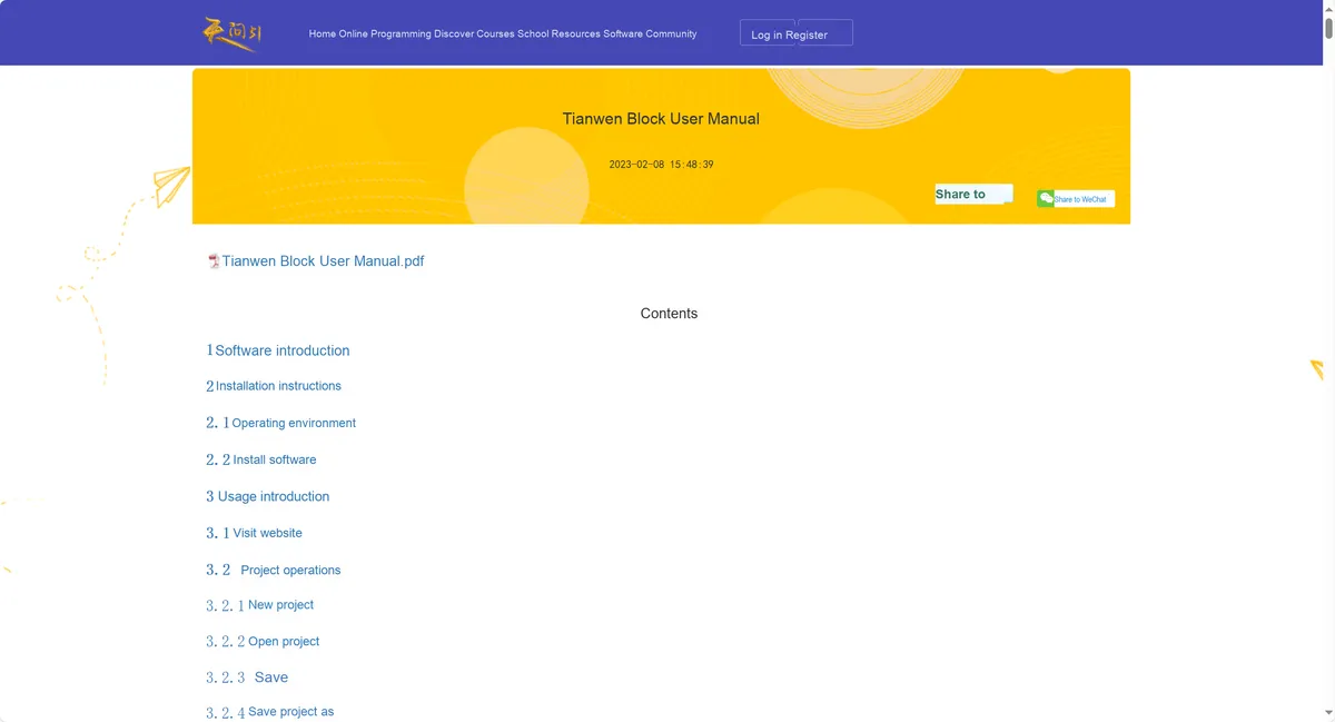
Datasheet available at the link: https://www.twen51.com/new/twen51/learning_show.php? id= 565
7.2 Unique Icons for PCB Silkscreen