Contents
- I. Module Introduction
- II. Introduction to Main Chips
- 2.1 Chip Overview
- 2.2 Pin Definition
- 2.3 Functional Block Diagram
- 2.4 Performance Parameters
- 2.5 Reference Circuit
- 2.6 Chip Configuration
- 2.7 Communication Interfaces and Related Protocols
- 2.8 PCB Routing Notes
- III. Circuit Engineering
- 3.1 Circuit Source Engineering
- 3.2 Module Usage Instructions
- 3.3 Application Experiment
- IV. Drivers
- 5. BOM & Recommended Alternative Parts
- 6. Revision History
- VII. Relevant Materials
- 7.1 Chip Datasheet
- 7.2 Unique Icons for PCB Silk Screen
I. Module Introduction
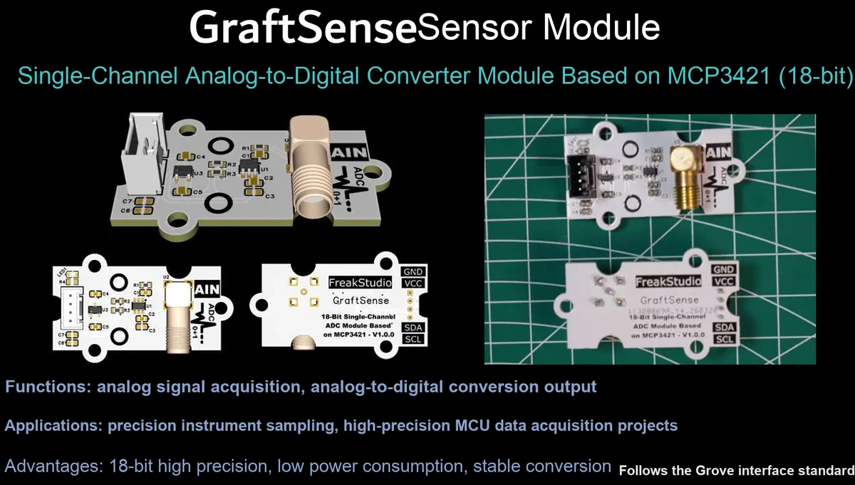
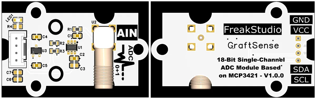
18-bit single-channel analog-to-digital conversion module based on MCP3421, which adopts the MCP3421 from Microchip Technology MCP3421 18-bit high-precision Σ-Δ type ADC chip solution, with built-in programmable gain amplifier and reference voltage source, supports single-channel differential input, and the optional sampling rates are 15/60/240 SPS;The communication interface complies with the standard I²C protocol, and is equipped with a 5V-to-3.3V LDO voltage regulator circuit and a power filter circuit. It is compatible with 3.3V level, and its 18-bit resolution corresponds to a minimum resolution voltage of 15.625μV. Featuring extremely low noise and ultra-high linearity, it is suitable for low-noise analog signal acquisition scenarios such as high-precision sensing and industrial measurement, and provides accurate and efficient high-precision analog signal digitization capability for the system.
II. Introduction to Main Chips
MCP3421 is a 18-bit single-channel Sigma-Delta high-precision ADC chip launched by Microchip Technology. It has a built-in reference voltage source and programmable gain amplifier ( PGA optional 1/2/4/8x), supports I ² C interface communication, sampling rate 15~ 240 SPS, power supply voltage 2.7V~ 5.5V, suitable for high-precision and low-noise analog signal acquisition scenarios.
2.1 Chip Overview
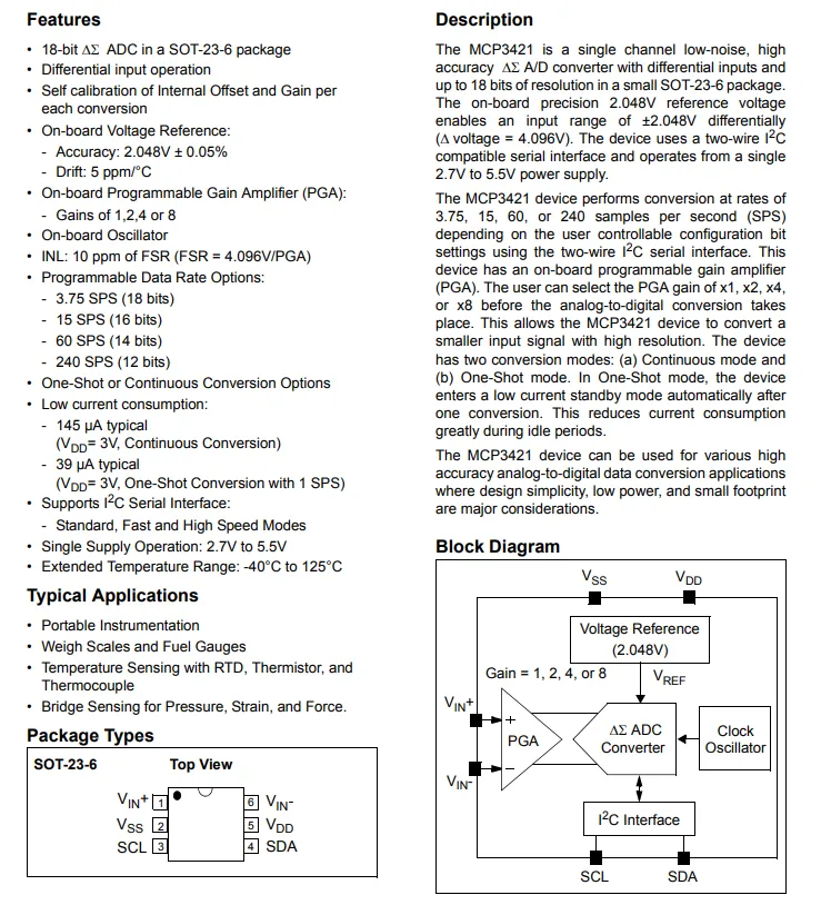
MCP3421 is an 18-bit single-channel Σ-Δ low-noise high-precision ADC housed in a SOT-23-6 package. It integrates a 2.048V reference voltage, a programmable gain amplifier (PGA with 1/2/4/8x gain options) and an on-chip oscillator, supports I²C interface communication, offers selectable sampling rates from 3.75 to 240 SPS, operates on a 2.7V to 5.5V supply, features self-calibration and low-power characteristics, and is suitable for applications such as portable instruments and high-precision sensing.
2.2 Pin Definition
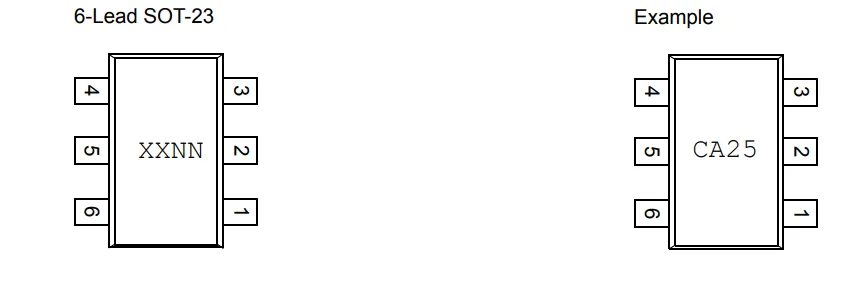
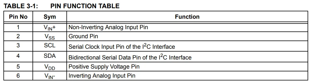
MCP3421 adopts a 6-pin SOT-23-6 package, with pin definitions as follows: Pin 1 VIN+(non-inverting analog input), Pin 2 VSS (ground), Pin 3 SCL (I²C clock input), Pin 4 SDA (I²C bidirectional data), Pin 5 VDD (positive power supply), Pin 6 VIN-(inverting analog input). It features a compact structure and facilitates high-density PCB layout.
2.3 Functional Block Diagram
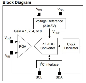
MCP3421 is a low-power Sigma-Delta architecture integrated with 18-bit resolution. ADC chip, which integrates a single differential input channel. The analog signal is first sent to a programmable gain amplifier (PGA with selectable gains of 1,2, 4, and 8 times) for amplification, and then the analog-to-digital conversion is completed by a Sigma-Delta modulator. The chip has a built-in 2.048V reference voltage source and on-chip oscillator, eliminating the need for external references and crystal oscillators. Through the I²C interface (SCL + SDA), the sampling rate, gain, and conversion mode can be configured, providing stable, efficient, and low-noise analog signal acquisition capabilities for high-precision sensing, industrial measurement, and other scenarios.
2.4 Performance Parameters
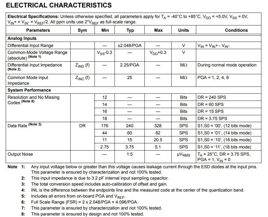
Electrical characteristics of the MCP3421: differential input range ±2.048V/ PGA, built-in 2.048V reference voltage, resolution ranges from 12 to 18 bits varying with the sampling rate (3.75 to 240 SPS), PGA = 1 and at 3.75 SPS, the effective accuracy reaches 18 bits, with an output noise of only 1.5 μV RMS. It features ultra-high linearity and low-impedance input characteristics, making it suitable for high-precision, low-noise analog signal acquisition scenarios.
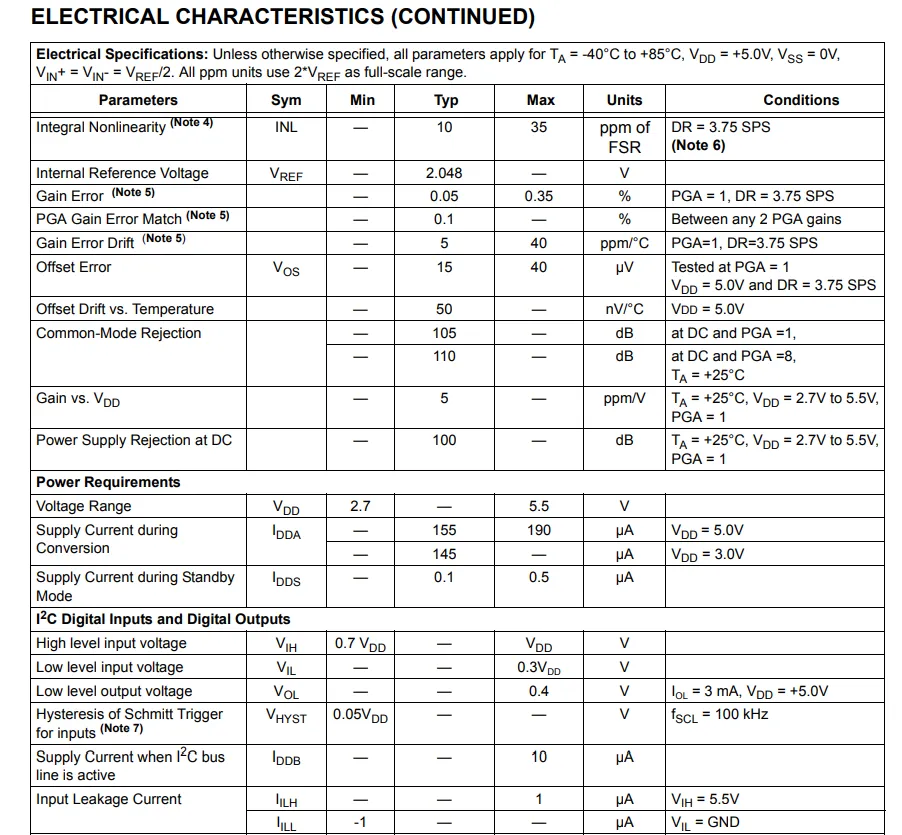
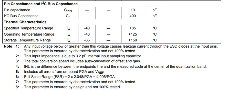
MCP3421 features excellent electrical performance: the typical value of integral nonlinearity (INL) is 10 ppm FSR, it has a built-in 2.048V reference voltage, a gain error < 0.35%, a maximum common-mode rejection ratio of 110dB, is compatible with a supply voltage of 2.7V~5.5V, draws an operating current of approximately 145μA and a standby current of only 0.1μA, its I²C interface is compatible with 3.3V/5V logic levels, the pin capacitance is 10pF, the maximum I²C bus capacitance is 400pF, and the operating temperature ranges from -40°C to 125°C, providing stable and reliable performance guarantee for high-precision and low-power signal acquisition.
2.5 Reference Circuit
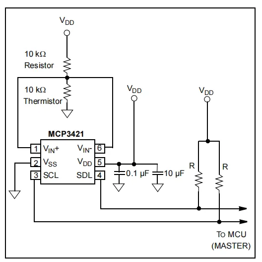
The typical reference circuit of MCP3421 adopts a differential input structure, VIN+ and VIN- are connected to a voltage divider network composed of a 10kΩ fixed resistor and a 10kΩ thermistor; 0.1μF and 10μF filter capacitors are connected in parallel at the power supply terminal, and the I²C interface (SCL + SDL) is connected to the MCU through pull-up resistors to realize high-precision analog signal acquisition such as temperature sensing.
2.6 Chip Configuration
None.
2.7 Communication Interfaces and Related Protocols
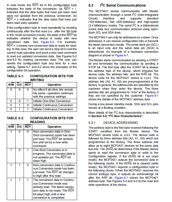
MCP3421 communicates with the host via the I²C interface, with a device address consisting of 1101 plus three programmable address bits. It supports standard/fast/high-speed I²C modes, and allows configuration of single/continuous conversion modes as well as data ready status query through the R / W, O / C, and RDY bits in the configuration byte, providing flexible control and data interaction capabilities for high-precision acquisition.
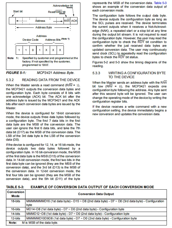
MCP3421 I²C communication address byte is 1101 + 3 address bits. During read operation, it outputs 2~3 bytes of conversion data (varying with the resolution from 12 to 18 bits) + 1 byte of configuration byte; during write operation, it can send a configuration byte to set the sampling rate, gain and conversion mode, providing a standardized and efficient I²C data interaction capability for high-precision signal acquisition.
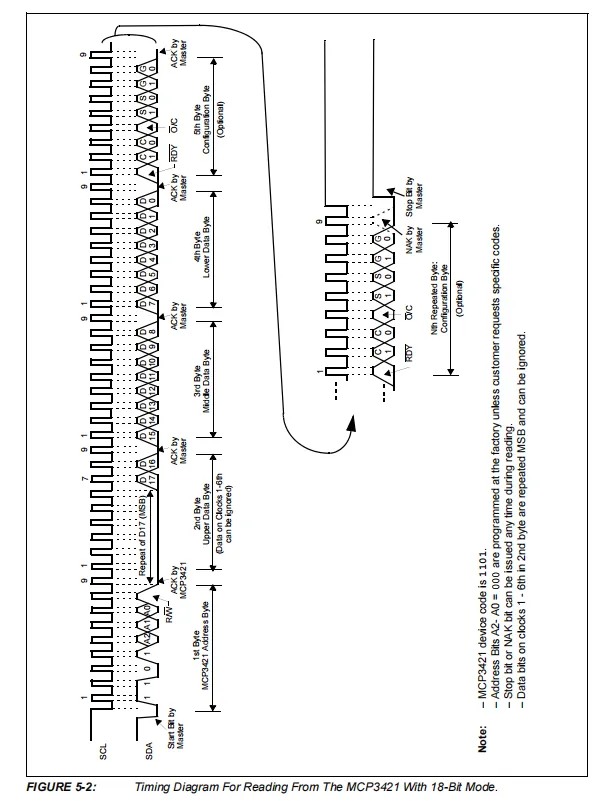
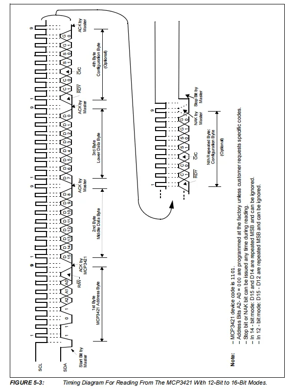
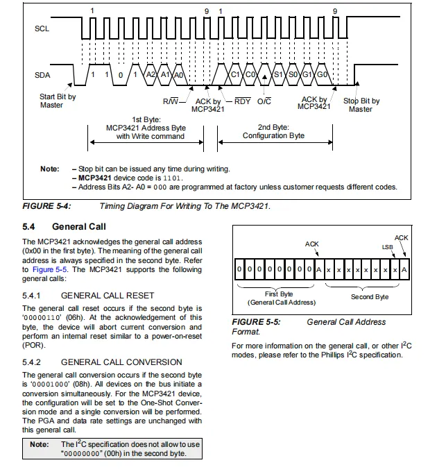
MCP3421 supports I²C write configuration timing and general call function: during a write operation, the master sends an address byte + a configuration byte to complete mode setting; it also supports the general call address 0x00, and can reset the chip via the 0x06 command and trigger a single conversion via the 0x08 command, providing efficient batch control and reset capabilities for multi-device bus scenarios.
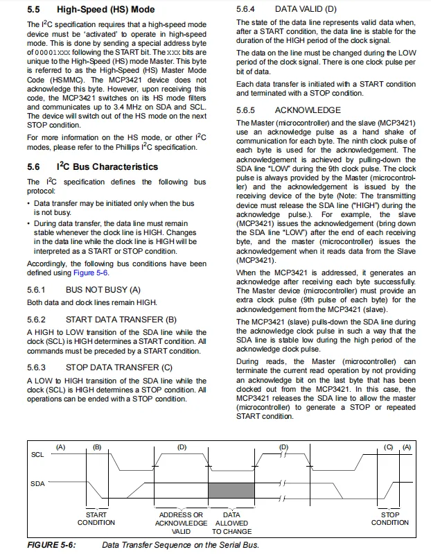
MCP3421 / I²C bus protocol and supports the high-speed (HS) mode (up to 3.4MHz). The bus must meet the timing constraints for idle state, START / STOP conditions, as well as data setup/hold. After each byte of communication, the slave pulls low SDA to complete the ACK, providing a reliable and efficient I²C high-speed communication guarantee for high-precision and low-noise signal acquisition.
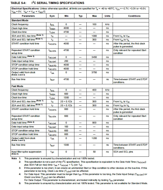
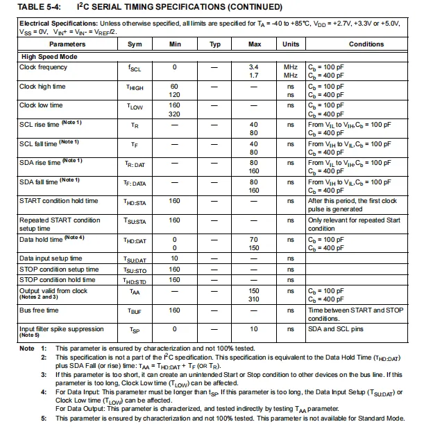
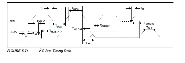
MCP3421 's I²C timing covers standard (100kHz), fast (400kHz) and high-speed (3.4MHz) modes, strictly defines the clock frequency, level pulse width, signal edge time, START / STOP conditions and data setup/hold time, and also specifies the noise suppression and bus capacitance constraints under each mode, providing standardized and reliable I²C communication timing guarantee for high-precision acquisition.
2.8 PCB Routing Notes
None.
III. Circuit Engineering
3.1 Circuit Source Engineering
To obtain the circuit source project, please follow the official account [Freak Embedded].
3.2 Module Usage Instructions
The schematic diagram of this module is shown below:
SCH_18-bit Single-Channel ADC Module Based on MCP3421-V1.0.0_2026-03-27.pdf 2.4 MB
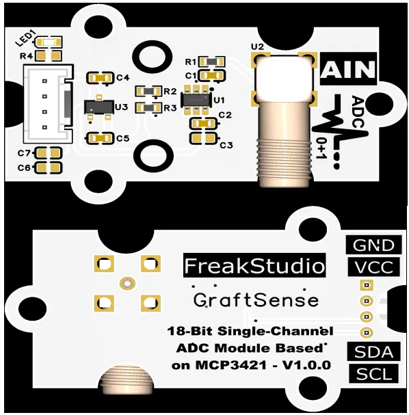
This module provides a standard I²C communication interface: it supports standard (100kHz), fast (400kHz) and high-speed (3.4MHz) I²C modes. The device address consists of 1101 plus three programmable address bits, and it is compatible with 3.3V logic level. An external 4.7kΩ pull-up resistor is required for both the SDA and SCL pins to ensure stable communication;This interface allows flexible configuration of PGA gain (1/2/4/8x), sampling rate (15/60/240 SPS) and conversion mode, and can stably read high-precision 12~18-bit ADC data. It is suitable for low-noise signal acquisition scenarios such as high-precision weighing, pressure sensing and industrial measurement, providing the system with accurate and efficient analog-to-digital signal interaction capability.
The AIN analog signal input interface of this module adopts the AIN analog signal input interface of this module adopts the SMA interface, which can be connected to the corresponding interface via an SMA adapter cable.
3.3 Application Experiment
Here, we use the GraftPort-RP2040 development board for testing. The 18-bit single-channel analog-to-digital conversion module based on MCP3421 communicates with the main controller via the I2C interface.
Here, we first use the HY2.0-4P connection cable to connect the module to the GraftPort-RP2040 development board's I2C0 interface:
The module connections are shown in the following table:
Development Board Pins | Module Pins | Description |
Pin 4 |
|
|
Pin 5 |
|
|
Meanwhile, connect the SMA cable to the portable signal generator, and set it to input a sine wave with a frequency of 1 Hz and an amplitude of 1.6 V to the module:
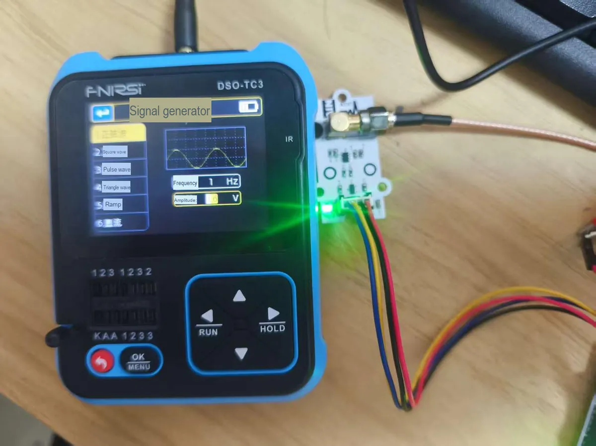
For instructions on how to use this signal generator, you can refer to:
17 ADC Analog-to-Digital Conversion - Draft Document Tutorial
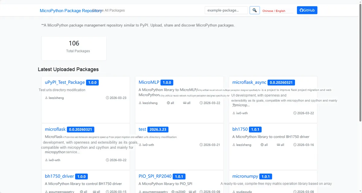
Here, we need to search for the relevant driver packages on uPyPI: https://upypi.net/zh/
Enter mcp3421_driver to search, and the following will be displayed:
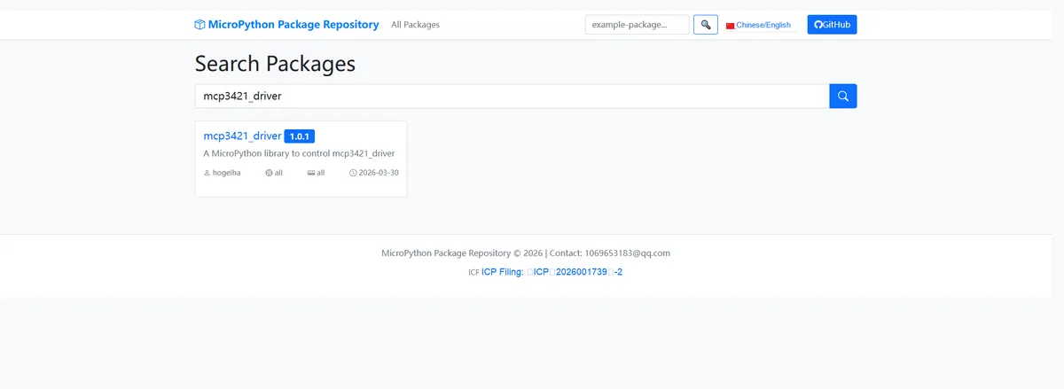
Click to copy the local installation command:
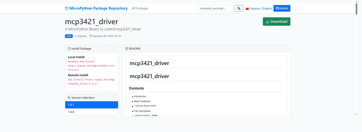
Import the module driver library code via the mip tool. Below are the usage commands for the mpremote tool:
mpremote mip install https://upypi.net/pkgs/mcp3421_driver/1.0.0Import the 18-bit single-channel analog-to-digital conversion module based on MCP3421 - MicroPython driver code, then copy the following main.py code into our project:
# Python env   : MicroPython v1.23.0
# -*- coding: utf-8 -*-
# @Time    : 2026/3/13 5:30 PM
# @Author  : octaprog7
# @File    : main.py
# @Description : Raspberry Pi Pico uses the MCP3421 analog-to-digital converter chip for voltage measurement, supporting one-shot and automatic continuous measurement modes

# ======================================== Import Modules =========================================
import sys
import time
from machine import I2C, Pin
from mcp3421 import I2cAdapter
from mcp3421 import Mcp342X

# ======================================== Global Variables ============================================
I2C_SCL_PIN = 3  # SCL pin number
I2C_SDA_PIN = 2  # SDA pin number
I2C_FREQ = 400_000  # I2C communication frequency
TARGET_SENSOR_ADDR = 0x68  # MCP3421 default I2C address (can be adjusted according to hardware configuration)
# Set the gain parameter (0 means default gain)
my_gain = 0
# Set the data rate parameter
my_data_rate = 1

# ======================================== Functions ============================================

# ======================================== Custom Classes ============================================

# ======================================== Initialization configuration ===========================================
time.sleep(3)
print("FreakStudio: MCP3421 ADC voltage measurement")

# Initialize the I2C bus
i2c_bus = I2C(1, scl=Pin(I2C_SCL_PIN), sda=Pin(I2C_SDA_PIN), freq=I2C_FREQ)
print(f"I2C_FREQ={I2C_FREQ}")
# Start scanning for devices on the I2C bus
devices_list: list[int] = i2c_bus.scan()
print("START I2C SCANNER")
print(devices_list)
# Check the I2C device scan result
if len(devices_list) == 0:
    print("No i2c device !")
    raise SystemExit("I2C scan found no devices, program exited")
else:
    print("i2c devices found:", len(devices_list))

# Iterate over the address list to initialize the target sensor
sensor = None
for device in devices_list:
    if device == TARGET_SENSOR_ADDR:
        print("I2c hexadecimal address:", hex(device))
        try:
            # Create the I2C adapter instance
            adapter = I2cAdapter(i2c_bus)
            # Create the MCP342X ADC instance (initialize the target sensor)
            sensor = Mcp342X(adapter)
            print("Target sensor initialization successful")
            break
        except Exception as e:
            print(f"Sensor Initialization failed: {e}")
            continue
else:
    raise Exception("No Mcp3421 sensor found on I2C bus")

adc = sensor

# Print the one-shot measurement mode message
print("---Single measurement mode---")

# Start one-shot measurement mode, configuring data rate, gain, channel and differential mode
adc.start_measurement(single_shot=True, data_rate_raw=my_data_rate, gain_raw=my_gain, channel=0, differential_channel=True)

# ========================================  Main Program  ============================================

# Print the sensor raw configuration message
print("---Basic raw sensor settings---")
# Get the sensor's common raw properties
gp = adc.get_general_raw_props()
# Print the common raw properties
print(gp)
# Print a separator line
print(16 * "--")
# Get the conversion cycle time
td = adc.get_conversion_cycle_time()
# Print the conversion cycle time (microseconds)
print(f"Conversion time [us]: {td}")
# Print the current resolution (bits)
print(f"Bits per reading: {adc.current_resolution}")
# Print the PGA gain value
print(f"PGA: {adc.gain}")
# Print a separator line
print(16 * "--")
# Loop to perform 33 one-shot measurements
for _ in range(33):
    # Wait for the conversion cycle to complete
    time.sleep_us(td)
    # Get the converted voltage value (not the raw value)
    val = adc.get_value(raw=False)
    # Print the measured voltage value
    print(f"Voltage: {val} Volts")
    # Start one-shot measurement again, keeping the same configuration
    adc.start_measurement(single_shot=True, data_rate_raw=my_data_rate, gain_raw=my_gain, channel=0, differential_channel=True)

# Print a separator line
print(16 * "--")
# Print the automatic measurement mode message
print("Automatic ADC measurement mode")
# Print a separator line
print(16 * "--")
# Start automatic continuous measurement mode, with the same parameters as one-shot mode
adc.start_measurement(single_shot=False, data_rate_raw=my_data_rate, gain_raw=my_gain, channel=0, differential_channel=True)
# Get the conversion cycle time
td = adc.get_conversion_cycle_time()
# Wait for the first conversion to complete
time.sleep_us(td)
# Print the conversion cycle time (microseconds)
print(f"Conversion time [us]: {td}")
# Print the current resolution (bits)
print(f"Bits per reading: {adc.current_resolution}")
# Initialize the loop counter and maximum value
_cnt, _max = 0, 333333
# Iterate to get the voltage values of the automatic measurement
for voltage in adc:
    # Print the voltage value from the automatic measurement
    print(f"Voltage: {voltage} Volts")
    # Check whether the counter exceeds the maximum value; if so, exit the program
    if _cnt > _max:
        sys.exit(0)
    # Wait for the conversion cycle to complete
    time.sleep_us(td)
    # Increment the counter by 1
    _cnt += 1
Burn the code, open the terminal, and the output is as follows:
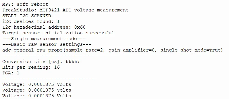
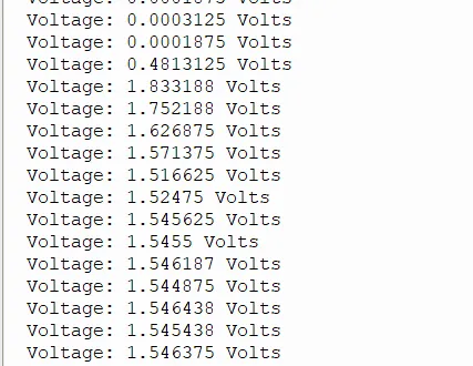
We can see that voltage measurement can be performed normally in both single and continuous modes, with the waveform as shown below:
IV. Drivers
mcp3421_driver-1.0.1.zip 20 KB
5. BOM & Recommended Alternative Parts
None.
6. Revision History
Document Version | Date of Revision | Modifier | Modified Content |
v1.0 | 2026-03-27 | Ling Gaoxing | Initialize the document |
v1.0.1 | 2026-04-05 | Li Zisheng | The homepage photo has not been taken, the production files have not been exported yet, and all other items have been sorted out completely. |
v1.0.2 | 2026-04-21 | Li Zisheng | The production documents have not been exported yet, while all the others have been sorted out completely. |
v1.1 | 2026-04-23 | Xin Ruili | Create an open version of the document, based on the internal document version v1.0.2. |
VII. Relevant Materials
7.1 Chip Datasheet
MCP3421.pdf 1.0 MB
7.2 Unique Icons for PCB Silk Screen