
Contents
- I. Unboxing and First Impressions of the Appearance
- 1.1 Packaging and Accessories
- 1.2 Card Appearance and First Impression
- II. Product Positioning and Core Platform
- 2.1 Product Positioning
- 2.2 i.MX 93 Processor Core Information
- 2.3 Differences from Common MCU Development Boards
- III. Onboard Hardware Resources
- 3.1 Memory and Storage
- 3.2 Wireless Tri-mode Module
- 3.3 Dual Gigabit Ethernet and Industrial Interfaces
- 3.4 Display, Camera and Audio
- 3.5 Buttons, LEDs and Auxiliary Resources
- IV. Interfaces and Scalability
- 4.1 Top-level Interface
- 4.2 Bottom Interface
- 4.3 Overview of Main Interfaces
- V. Power Supply, Startup and Commissioning
- 5.1 Power Supply Requirements
- 5.2 Startup Mode and DIP Switches
- 5.3 Dual Serial Port Debugging Interface
- VI. Windows Environment Preparation
- 6.1 CH343SER Serial Port Driver
- 6.2 Tera Term Tool
- 6.3 NXP UUU Burning Tool
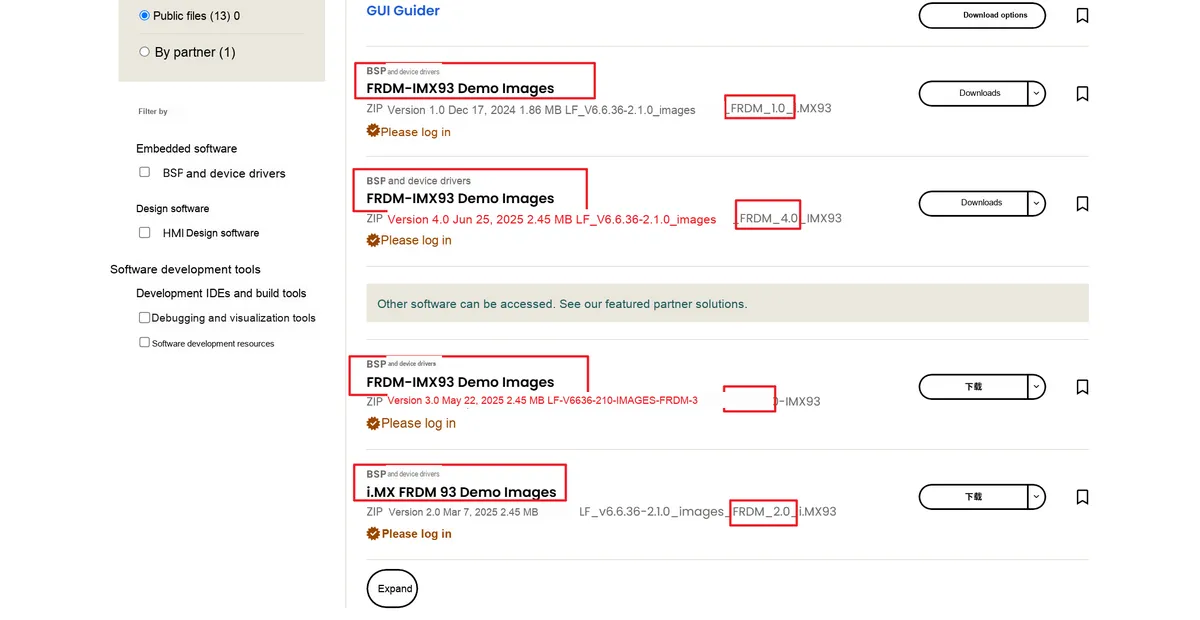
- 6.4 Official Pre-compiled Linux Mirror
- 6.5 Preparation of Test Cables and Peripherals
- VII. Factory System Live Demo
- 7.1 Wiring and Power-on of the Development Board
- 7.2 Factory eMMC Linux System Boot
- 7.3 Startup Log
- 7.4 Linux Desktop and System Information
- 7.5 Full Power-on Video Demonstration
- 7.6 Official Demo of GoPoint
- VIII. Official Mirror Redeployment
- 8.1 Official mirror preparation
- 8.2 Enter USB Serial Downloader Mode
- 8.3 Using UUU to Flash Image to microSD Card
- 8.4 Switch to microSD Boot
- 8.5 New System Startup and Function Verification
- IX. Simple Function Test
- 9.1 System Information and Startup Time
- 9.2 HDMI Display
- 9.3 Wired Network
- 9.4 Basic Wi-Fi Connection
- X. Introduction to Other Capabilities and Software Ecosystem
- 10.1 Cortex-M33 Heterogeneous Processing
- 10.2 Bluetooth LE
- 10.3 802.15.4 and OpenThread
- XI. Practical Experience and Summary
- 11.1 Advantages
- 11.2 Application Scenarios
- 11.3 Comprehensive Evaluation
- XII. Common Issues About Burning Mirror
- Timeout while burning mirror
- 13. References
I. Unboxing and First Impressions of the Appearance
1.1 Packaging and Accessories
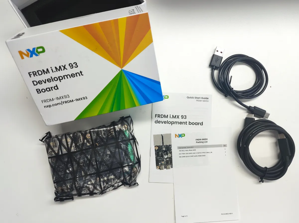
Figure 1 Packaging and Accessories of FRDM-IMX93 Development Board (Source: On-site Photo)
The FRDM i.MX 93 kit is designed for quick start, and its core contents include the development board itself, a quick start guide, and a USB cable for connecting to a PC. As specified in the quick start guide, the Linux BSP mirror is preinstalled in the eMMC, so developers can prioritize verifying the factory system upon receiving the board before deciding whether to redeploy the official mirror.
Project | Description |
FRDM-IMX93 Development Board | Main body of the development board |
USB Type-C to Type-C cable | For USB Type-C PD power supply |
USB 2.0 Type-C to Type-A cable | Used for serial port debugging or connecting to a PC |
Quick Start Guide | Quick Start Guide |
Linux BSP image | Pre-burned in eMMC |
1.2 Card Appearance and First Impression
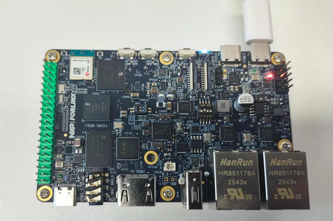
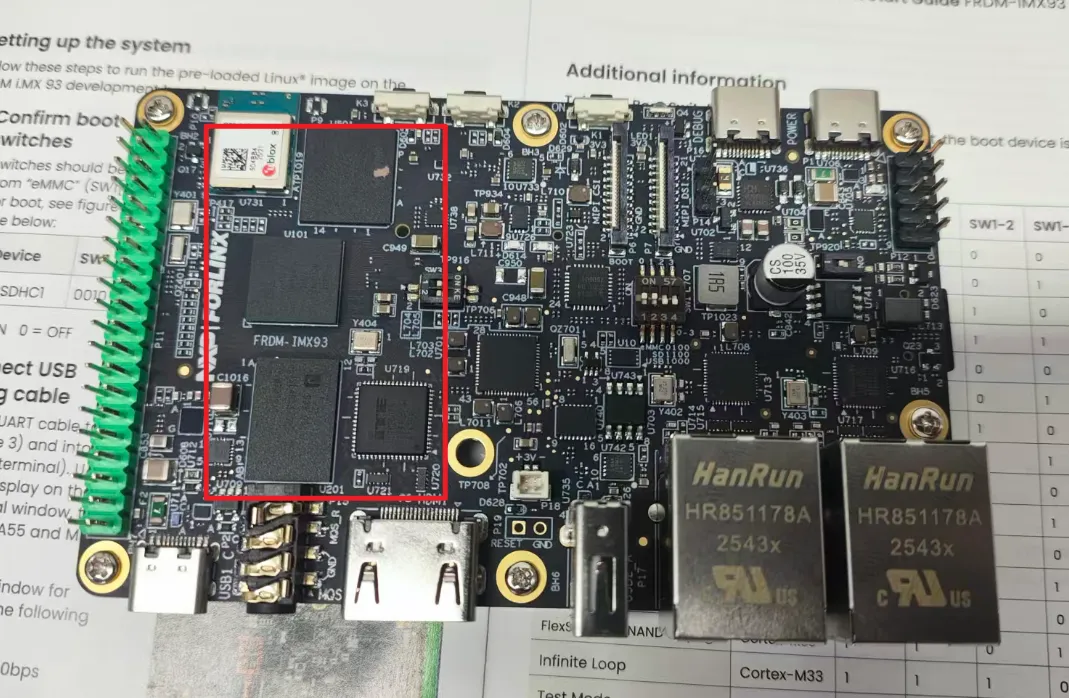
The FRDM-IMX93 features a compact form factor of 105 mm x 65 mm, with a standard 10-layer FR-4 PCB design. It integrates the i.MX 93 application processor, 2 GB LPDDR4X, 32 GB eMMC, dual Gigabit Ethernet, a tri-mode wireless module, MIPI camera/display interfaces, HDMI, USB, CAN, a debug UART port, and a 2x20 expansion header on board.
From the perspective of interface layout, it is more like an MPU platform oriented to Linux edge computing, lightweight AI and industrial networking verification, rather than a traditional MCU entry-level board that only runs bare-metal systems or RTOS.
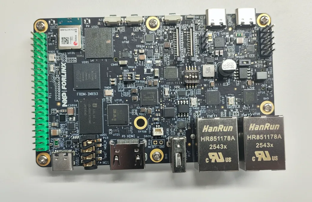
Figure 2 Front View of FRDM-IMX93 Development Board (Source: On-site Photo)
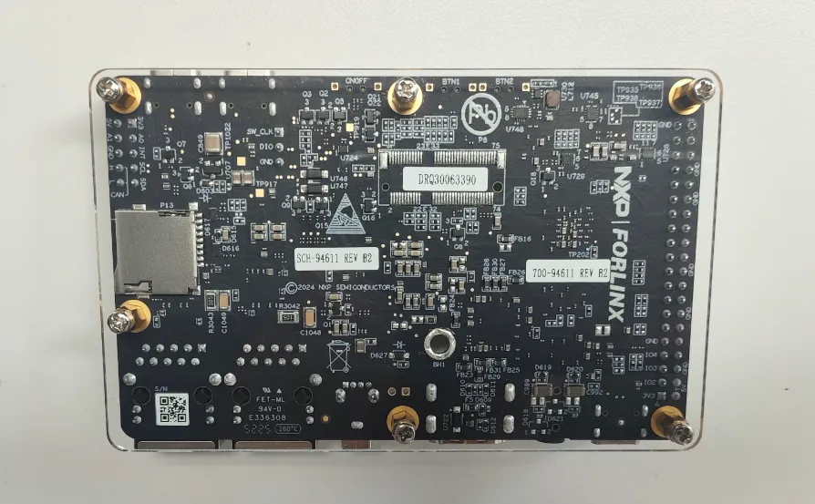
Figure 3 Back View of FRDM-IMX93 Development Board (Source: On-site Photo)
II. Product Positioning and Core Platform
2.1 Product Positioning
The FRDM i.MX 93 is an entry-level development board launched by NXP for the i.MX 93 application processor. It is not designed to stack the most complex peripherals, but to demonstrate the common capabilities of the i.MX 93 in a small-sized, low-cost form factor, making it suitable for verifying Linux systems, edge AI, human-machine interfaces, industrial connectivity and multi-protocol wireless functions before customizing hardware.
- Industrial HMI and Lightweight Graphical Interfaces
- Edge AI Inference and Sensor Data Processing
- High-Efficiency Linux IoT Gateway
- Multi-connection prototype for Ethernet, Wi-Fi 6, Bluetooth LE and 802.15.4
- Verification of accessories such as camera modules, display screens, and audio HATs
2.2 i.MX 93 Processor Core Information
Project | Parameters/Capabilities | Evaluation Value |
CPU | Dual-core Arm Cortex-A55 @ 1.7 GHz + single-core Arm Cortex-M33 @ 250 MHz | The A55 cores run Linux applications, while the M33 cores can handle real-time or low-power tasks. |
NPU | Arm Ethos-U65 microNPU, 0.5 TOPS @ 1 GHz | For GoPoint AI Demo, ML Benchmark or lightweight inference verification |
Safety | EdgeLock Secure Enclave, secure boot, key storage, etc. | Suitable for device identity, firmware protection and secure connection scenarios |
Connect | 2x GbE, 2x USB 2.0, CAN-FD, UART, SPI, I2C, I3C, FlexIO | Covers gateways, industrial interfaces and multi-peripheral prototypes |
multimedia | MIPI-CSI, MIPI-DSI, LVDS/HDMI, 2D graphics, PDM, I2S, MQS | covering display, camera, audio and HMI demonstrations |
Note: The product page block diagram of FRDM-IMX93.pdf is labeled as 2x Cortex-A55 @ 1.7 GHz, 1x Cortex-M33 @ 250 MHz, 0.5 TOPS NPU @ 1 GHz
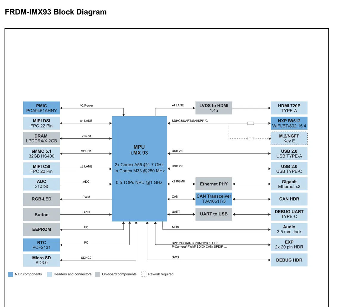
Figure 2 Block Diagram of the Official Product Page for FRDM-IMX93 (Source: NXP)
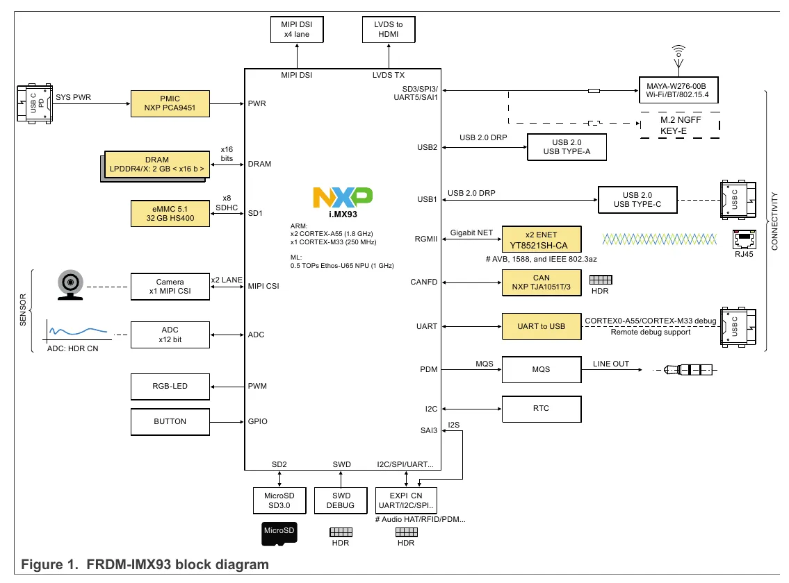
Figure 3 Block Diagram of FRDM-IMX93 Board-Level System (Source: NXP)
2.3 Differences from Common MCU Development Boards
General MCU development boards typically focus on bare-metal systems, RTOS, GPIO, serial ports and basic peripherals, while the FRDM i.MX 93 centers on Linux BSP, graphical interfaces, network connectivity, edge AI and multimedia input/output. The inclusion of the Cortex-M33 allows it to retain real-time control or low-power co-processing capabilities, yet the core user experience of the entire board should revolve around the A55 Linux system.
III. Onboard Hardware Resources
3.1 Memory and Storage
Resources | Manual Information | Description |
DRAM | 2 GB LPDDR4X, Micron MT53E1G16D1FW-046 AAT:A | LPDDR4X mode is selected by default |
eMMC | 32 GB eMMC 5.1, FORESEE FEMDRM032G-A3A55 | Default boot device, the factory preinstalled system is stored in eMMC |
microSD card | MicroSD 3.0, 4-bit, connected to uSDHC2 | Test media suitable for redeployment as an official mirror |
2 GB of LPDDR4X is sufficient for basic Linux desktops, network connectivity, lightweight demos, and entry-level AI inference experiments, while the 32 GB eMMC reduces the instability caused by booting from external storage.
3.2 Wireless Tri-mode Module
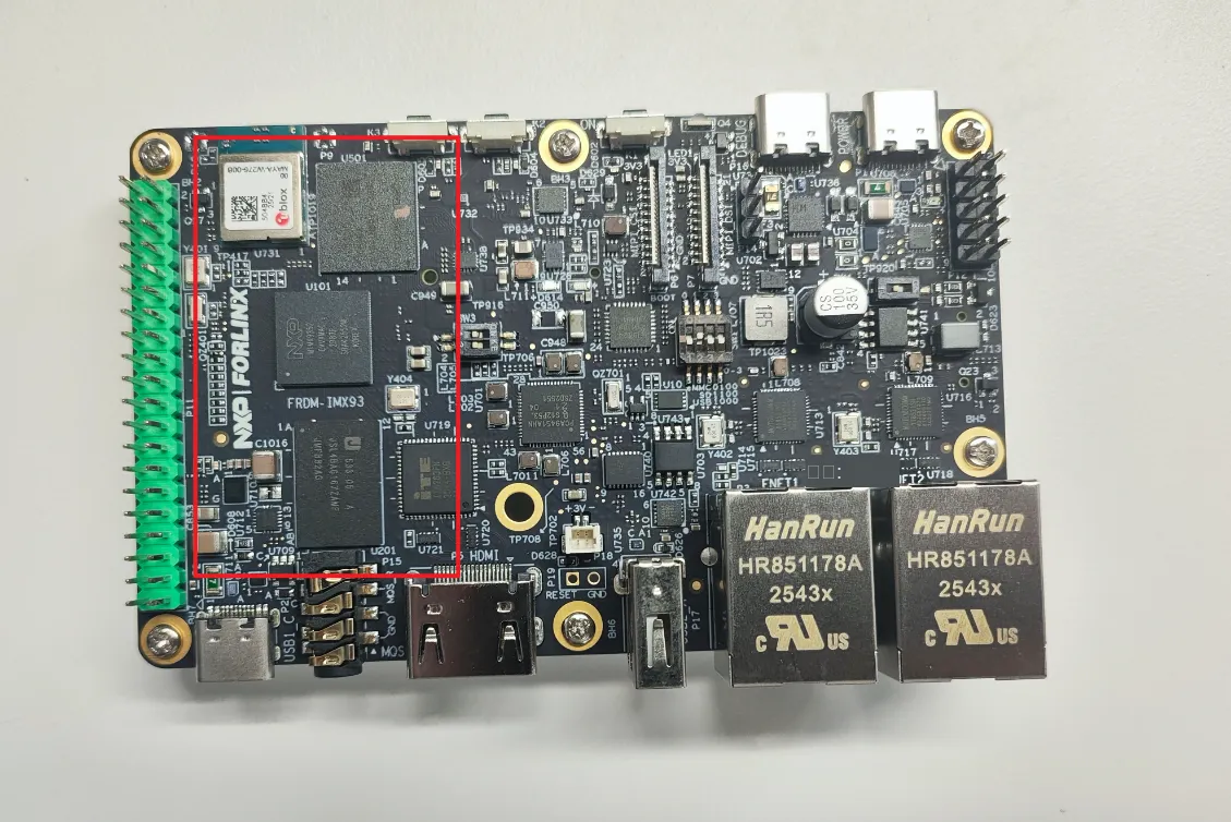
It is equipped with an onboard MAYA-W276-00B module, which is based on the NXP IW612/u-blox solution and supports Wi-Fi 6, Bluetooth/Bluetooth LE 5.4 and 802.15.4. By default, the host interfaces are configured as follows: Wi-Fi over SDIO, Bluetooth LE over UART, and 802.15.4 over SPI.
This module shares signals including SD3, UART5, SAI1, and SPI3 with the M.2 Key E interface, and the onboard tri-mode module is selected by default via a 0-ohm resistor. If you want to switch to the M.2 Key E slot, you need to rework the resistors according to Table 15 in the manual, so it should not be stated that the M.2 wireless adapter is plug-and-play by default.
3.3 Dual Gigabit Ethernet and Industrial Interfaces
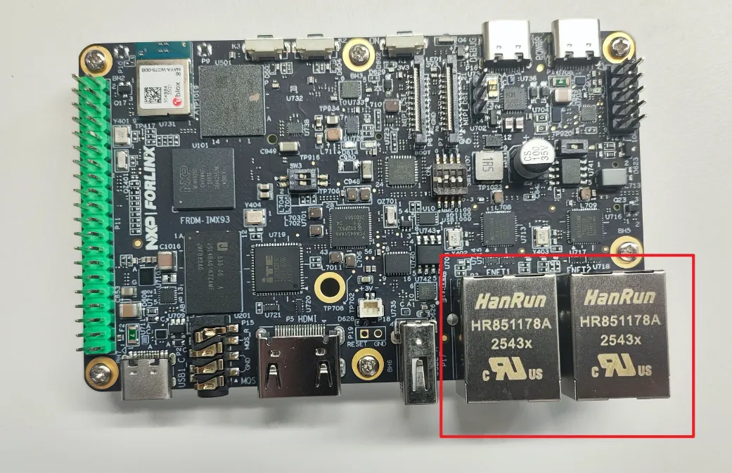
- P3: 10/100/1000 Mbit/s RGMII, with Ethernet PHY model YT8521, supporting TSN.
- P4: 10/100/1000 Mbit/s RGMII, with Ethernet PHY model YT8521.
The i.MX 93 Ethernet subsystem supports simultaneous operation of dual Gigabit Ethernet controllers, and is compatible with EEE, Ethernet AVB and IEEE 1588. It is recommended to only verify the basic connectivity of one Ethernet port in the evaluation; items such as dual-port Ethernet bridging and full-load operation of both ports can be presented as reference information or extended tests, and are not included as mandatory test items.
In terms of industrial interfaces, the P12 is equipped with a high-speed CAN transceiver for connection, the model of which is NXP TJA1051T/3. It also leads out I2C/I3C and ADC channels, making it suitable for industrial sensors or bus expansion prototypes.
3.4 Display, Camera and Audio
module | Onboard Interface | Description |
Camera | MIPI-CSI, P6, 22-pin FPC | 2-lane MIPI CSI, compatible with supporting camera accessories |
Show | MIPI-DSI, P7, 22-pin FPC | 4-lane MIPI DSI, suitable for screen accessory verification |
HDMI | P5 | Output via the IT6263 LVDS-to-HDMI conversion chip |
Audio | MQS, P15; I2S expandable via EXPI | Suitable for basic audio output or external audio HAT |
3.5 Buttons, LEDs and Auxiliary Resources
The board provides resources such as startup DIP switches, push buttons, RGB LEDs, and power/wireless status indicators, which are suitable for observing the board's operating status during power-on, system boot, wireless status monitoring, and basic demo execution.
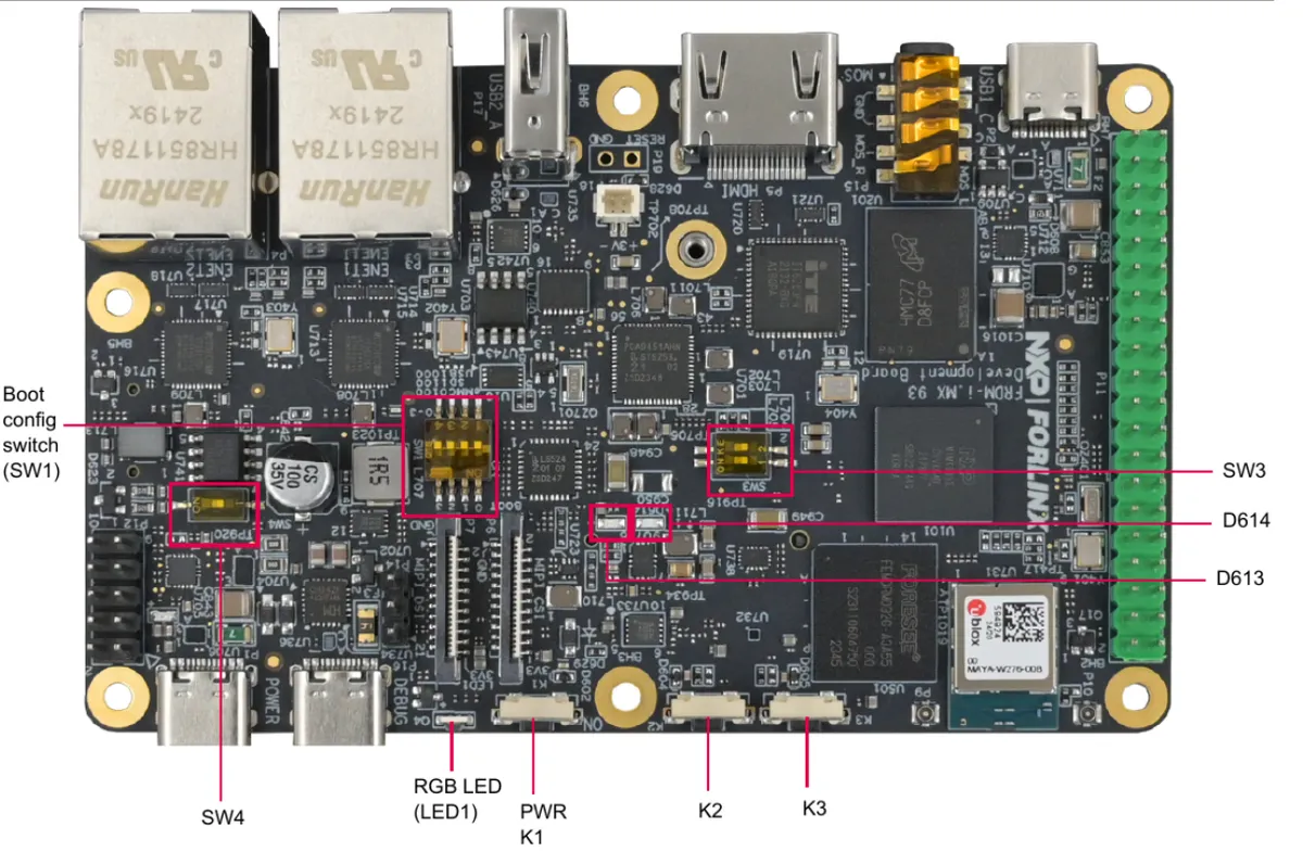
Figure 4 Labeling of Buttons and LEDs on FRDM-IMX93 (Source: NXP)
IV. Interfaces and Scalability
4.1 Top-level Interface
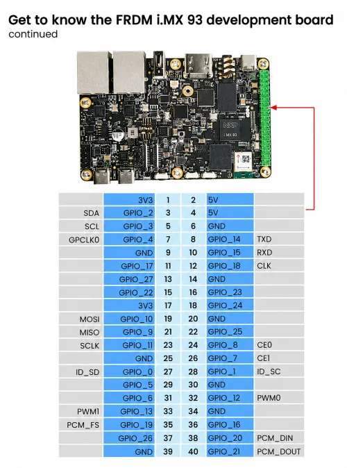
The top-level interfaces include dual RJ45, USB Type-A, HDMI, MQS audio, USB Type-C power supply, USB Type-C Debug, USB Type-C download/device port, MIPI-CSI, MIPI-DSI, SWD, P12 custom interface and 2x20 EXPI.
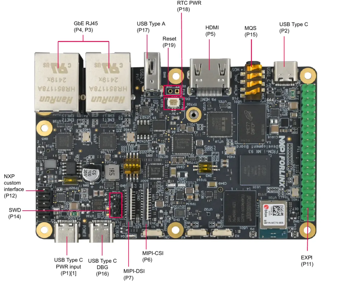
Figure 5 Top Interface Labels of FRDM-IMX93 (Source: NXP)
4.2 Bottom Interface
The bottom mainly features a visible M.2 Key E slot and a microSD card slot. The microSD card slot was used for official mirror redeployment in this evaluation, while the M.2 Key E slot, which shares signals with the onboard wireless module, will only be introduced in terms of its interface capabilities.
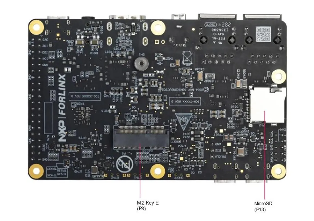
Figure 6 Labeling of Bottom Interfaces of FRDM-IMX93 (Source: NXP)
4.3 Overview of Main Interfaces
API | Tag No. | Applications |
|---|---|---|
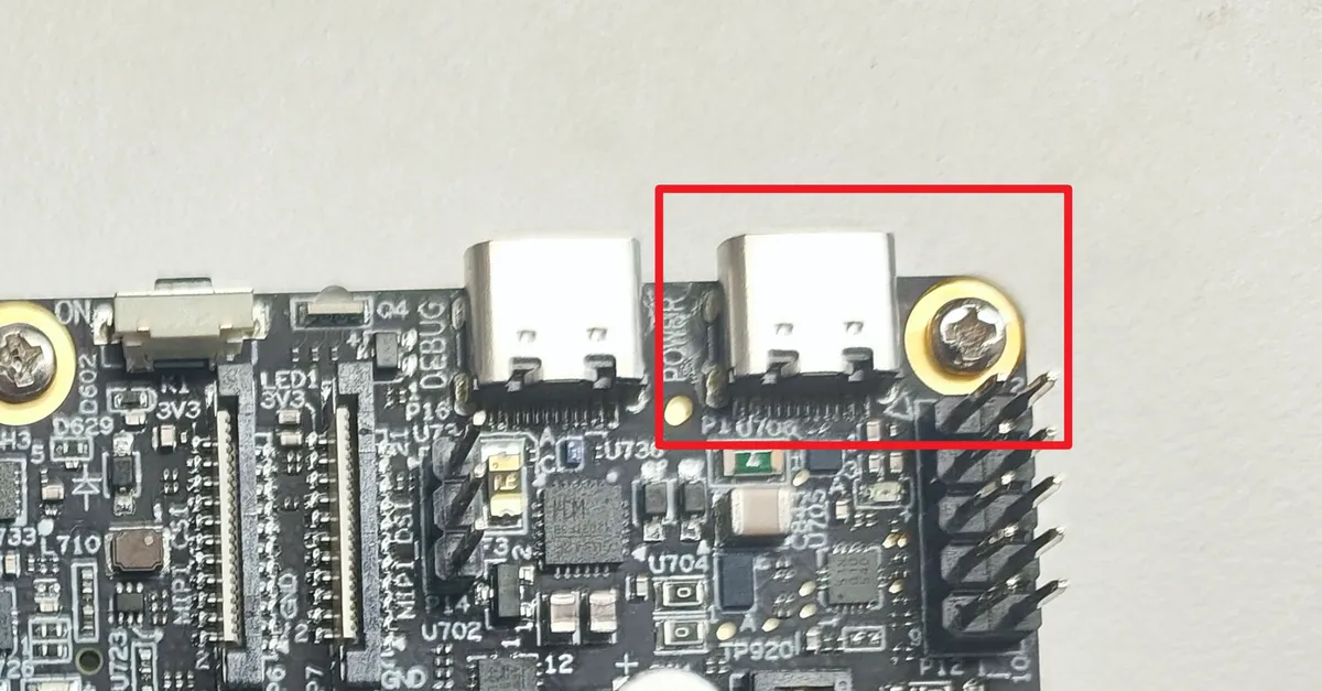
USB Type-C PWR | P1 | Main power port, USB Type-C PD, the user manual requires the main power input of the board to be 12 V - 20 V |
USB Type-C | P2 | USB 2.0, can function as host/device |
RJ45 | P3/p4 | Dual Gigabit Ethernet |
HDMI | P5 | LVDS-to-HDMI Output |
MIPI-CSI | P6 | Camera Interface |
MIPI-DSI | P7 | Display Interface |
M.2 Key E | P8 | Share wireless-related interfaces, with the default signal connected to the onboard tri-mode module |
EXPI | P11 | 2x20 expansion, I2S/UART/I2C/GPIO, etc. |
NXP custom interface | P12 | CAN, I2C/I3C, ADC |
microSD card slot | P13 | SD3.0, can be used as a boot medium |
SWD | P14 | SWD Debugging Related |
MQS | P15 | Audio Output |
USB Type-C DBG | P16 | USB to Dual UART Debug Port |
USB Type-A | P17 | USB 2.0 host/device |
V. Power Supply, Startup and Commissioning
5.1 Power Supply Requirements
It is recommended to use a 45 W USB Type-C PD power adapter for the development board. The power adapter itself supports multiple PD voltage levels, whereas the main power input at connector P1 on the board should operate within the range of 12 V to 20 V as specified in the user manual, and should be negotiated to the 15 V or 20 V level in actual use. The power adapter is not included with the development board kit and needs to be prepared separately in advance.
The main power components on the board include MP8759GD, PCA9451AHNY PMIC, MP1605C and MP2147GD, which are responsible for power conversion for SYS_5V, SoC/DDR/I/O, multimedia interfaces, and M.2/wireless modules respectively.
5.2 Startup Mode and DIP Switches
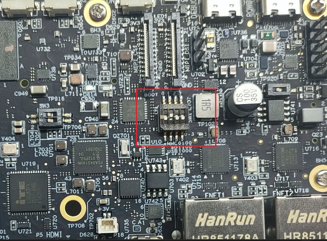
SW1 [4–1]is the boot configuration switch. By default, the boot device is eMMC/uSDHC1
| Purpose | BootCore | SW1-4 | SW1-3 | SW1-2 | SW1-1 |
|---|---|---|---|---|---|
| USB Serial Downloader mode | Cortex-A55 | 0 | 0 | 0 | 1 |
| eMMC boot | Cortex-A55 | 0 | 0 | 1 | 0 |
| microSD card boot | Cortex-A55 | 0 | 0 | 1 | 1 |
The dial switch direction, mirror file name and UUU parameters must be subject to the actually downloaded software package, the latest official guide and the silkscreen on the board.
5.3 Dual Serial Port Debugging Interface
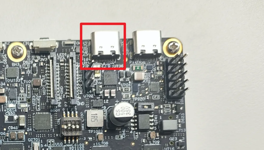
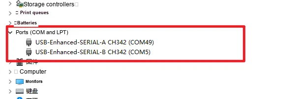
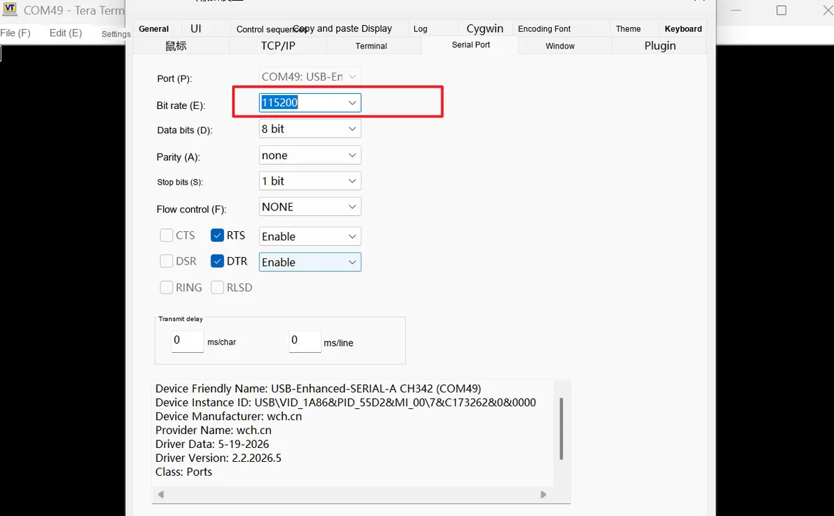
The FRDM-IMX93 provides two debug serial ports via the CH342F USB-to-Dual UART on P16. After installing the CH342F/CH343 series Windows serial port driver, two COM ports are expected to be enumerated on the PC side.
Serial Port | Applications |
|---|---|
COM Port 1 | Cortex-A55 System Debugging |
COM Port 2 | Cortex-M33 System Debugging |
Parameters | value |
|---|---|
Baud Rate | 115200 |
data bit | 8 |
parity bit | None |
Stop bit | 1 |
flow control | None |
VI. Windows Environment Preparation
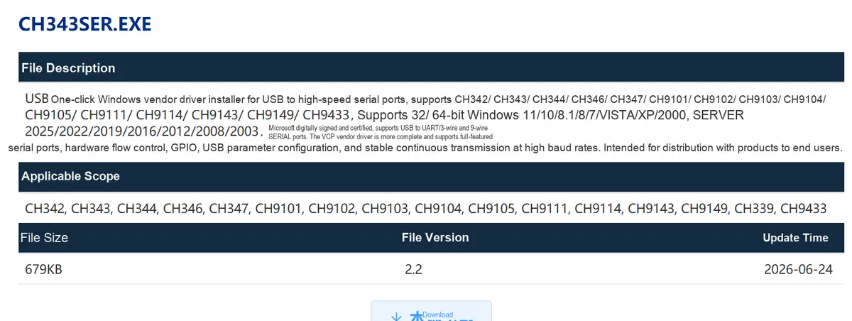
6.1 CH343SER Serial Port Driver
For Windows, you need to install CH343SER.EXE, which serves as the USB-to-serial driver for the CH342F/CH343 series. After the development board is connected, two COM ports are expected to appear: COM Port 1 corresponds to the Cortex-A55, and COM Port 2 corresponds to the Cortex-M33.
6.2 Tera Term Tool
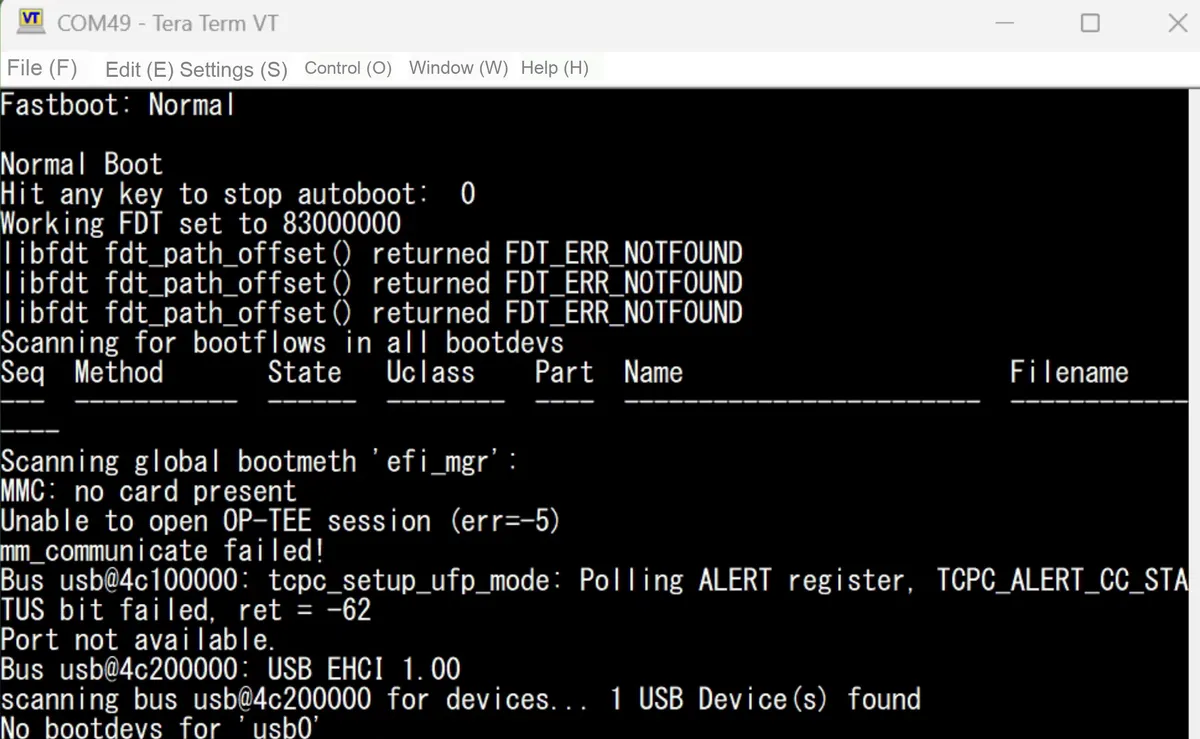
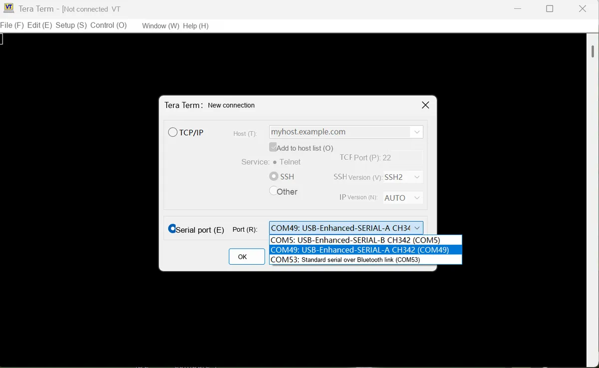
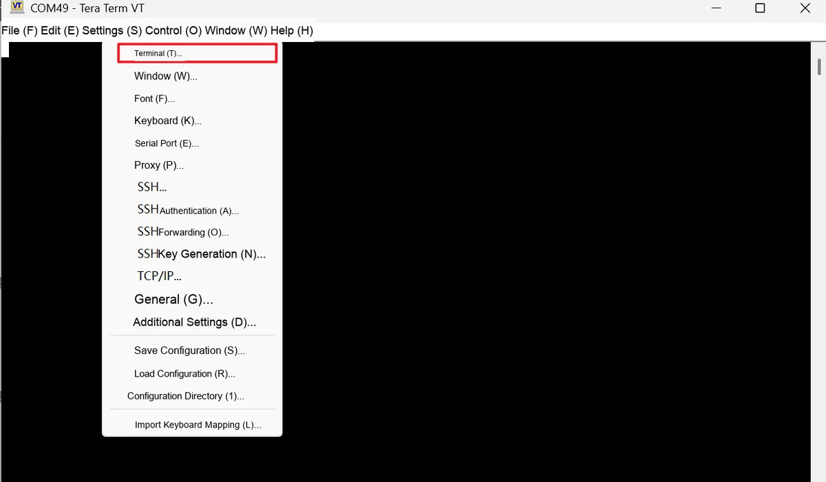
The existing Tera Term can be used to view U-Boot and Linux boot logs as well as input Linux commands. The serial port parameters are 115200 baud rate, 8 data bits, no parity, 1 stop bit, and no flow control.
6.3 NXP UUU Burning Tool
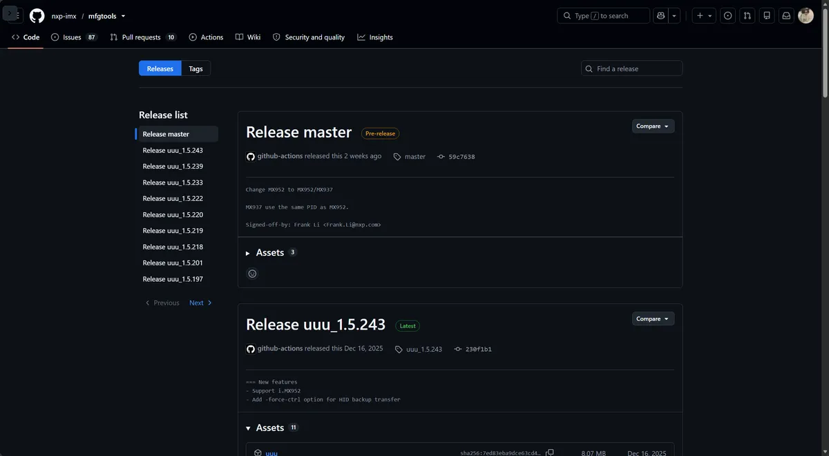
NXP Universal Update Utility (UUU) is a commonly used i.MX mirror flashing tool on Windows. It generally does not require traditional installation and can be invoked via the command line after download. This time, it is only used to write the official mirror to the microSD card, and will not serve as the main solution to overwrite the factory-programmed eMMC.
6.4 Official Pre-compiled Linux Mirror
It is preferred to use the officially pre-compiled Linux/Yocto mirror provided by NXP, without setting up a complete Yocto compile environment, nor compiling the Linux kernel, U-Boot, device tree or the full system on your own. The mirror version, compression format and file name shall be subject to the actual downloaded package.
6.5 Preparation of Test Cables and Peripherals
- 45 W USB Type-C PD power adapter, it is recommended to negotiate to 15 V or 20 V in actual use.
- USB Type-C data cable, intended for the P16 debug port.
- HDMI display, HDMI cable, USB mouse or USB flash drive.
- microSD card and card reader, for official mirror deployment.
- Network cables and available routers/switches for basic wired network testing.
VII. Factory System Live Demo
7.1 Wiring and Power-on of the Development Board
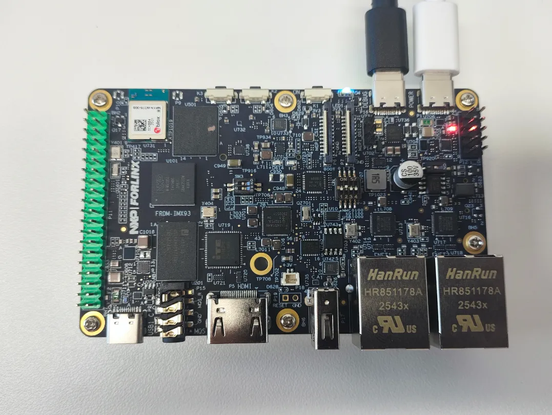
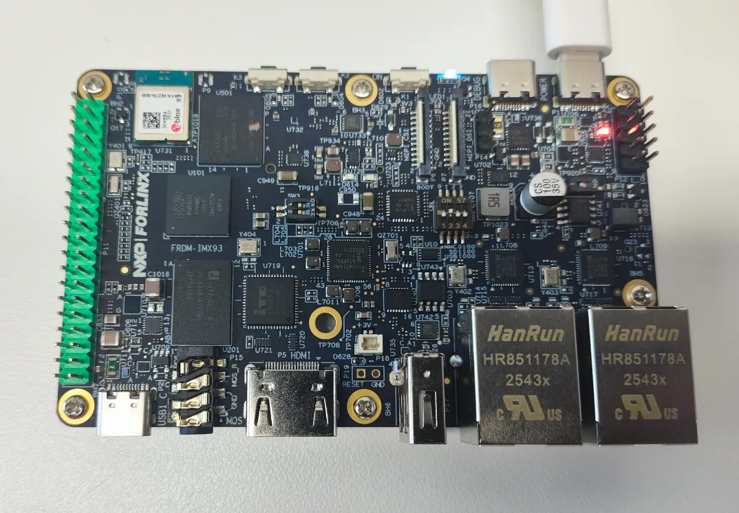
This real-machine demo prioritizes the factory-default eMMC system. The wiring connections include P1 USB Type-C PD power supply, P16 debug serial port connected to a PC, HDMI connected to a display, and a USB mouse or USB flash drive connected when necessary.
7.2 Factory eMMC Linux System Boot
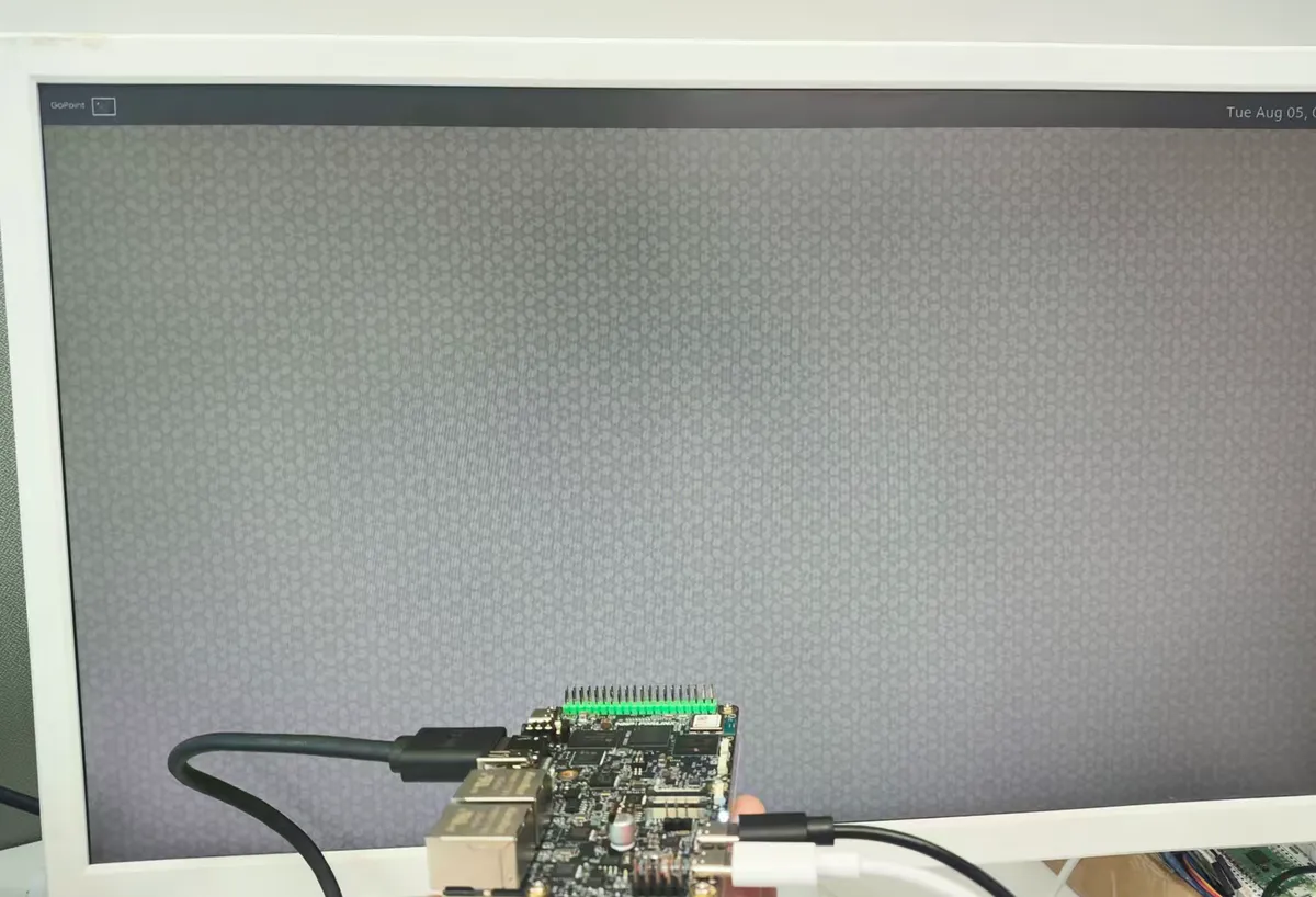
The Linux BSP is pre-installed in the factory eMMC of the FRDM i.MX 93. After power-on, observe the boot process of U-Boot and Linux via the serial port, and meanwhile check whether the graphical interface outputs properly through HDMI.
7.3 Startup Log
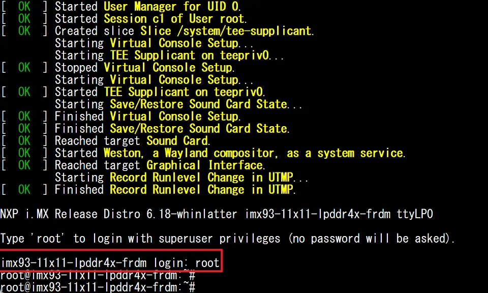
VOFA+ is primarily used to view boot logs and enter simple Linux commands. It is recommended to save the complete log from power-on until the login prompt appears, so as to record the U-Boot version, kernel version and boot time consumption.
Boot log.mp4 7.5 MB
Enter username:
rootNo password required
uname -a
View kernel information

imx93-11x11-lpddr4x-frdm
This is the host name of the device, where:
imx93: i.MX 93 Platform11x11: Corresponding to the chip package or platform configuration namelpddr4x: Uses LPDDR4X memoryfrdm: FRDM Development Board
6.18.2-1.0.0-gf49f45233f7b
This is the Linux kernel version:
6.18.2: Main version of the Linux kernel1.0.0: NXP BSP release version for this kernelgf49f45233f7b: Git commit ID corresponding to the kernel source code
It can be used to determine the specific kernel source code version currently in use by the mirror.
#1
Indicates that this is the first build number generated by this kernel configuration.
SMP
Indicates that the kernel supports multi-processor or multi-core operation.
Currently, the i.MX 93 features two Cortex-A55 cores, enabling Linux to schedule both cores simultaneously.
PREEMPT
Indicates that the kernel has enabled the preemption feature.
Simply put, when a high-priority task arrives, the kernel can suspend the current task and switch to the more important one in a timelier manner, which helps reduce system response latency.
Wed Feb 11 18:37:47 UTC 2026
This is the kernel compile time, not the current time of the development board.
aarch64
Indicates that the currently running program is:
64-bit ARM architecture Linux system.
GNU/Linux
which indicates that the system consists of the Linux kernel and GNU/Linux user-space tools.
cat /etc/os-release
The current system is displayed as NXP i.MX Release Distro 6.18-whinlatter, which is a Linux system provided by NXP for the i.MX platform.
lscpu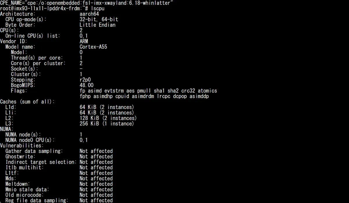
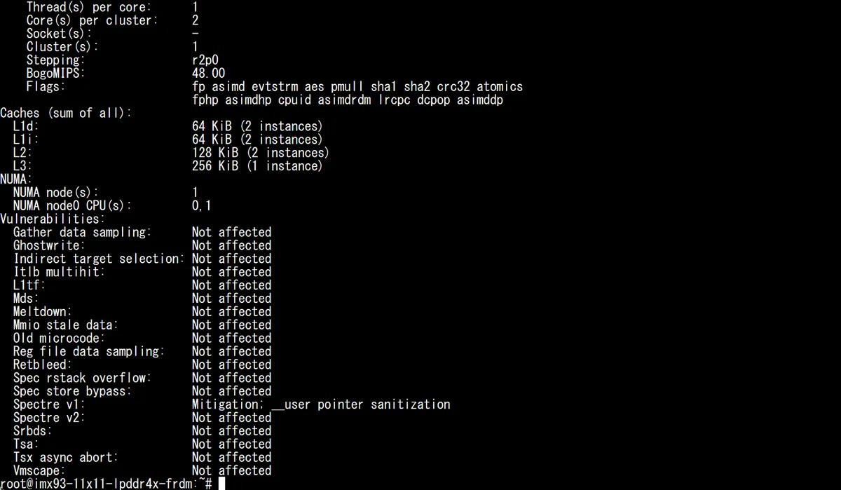
The system shows that two Cortex-A55 cores are detected, and both cores are online. The processor supports floating-point operations, NEON vector operations, as well as instructions such as AES, SHA, and CRC32. The onboard Cortex-M33 and NPU are not ordinary CPU cores for Linux, so they will not be displayed in lscpu.

free -h
The system shows that the available memory is approximately 1.9 GiB, the current usage is around 222 MiB, and the free memory is roughly 1.7 GiB, indicating that the memory footprint is relatively low right after the system boots. No Swap is configured, which is a common practice in embedded Linux systems.
df -h and lsblk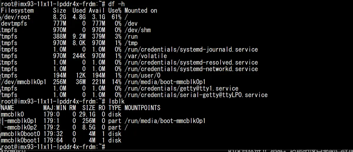
The onboard 32 GB eMMC is recognized by the system as approximately 29.1 GiB. It currently contains a 256 MiB boot partition and a root file system partition of around 8.5 GiB. About 4.8 GiB of the root file system has been used, leaving roughly 3.1 GiB of free space.
ip addr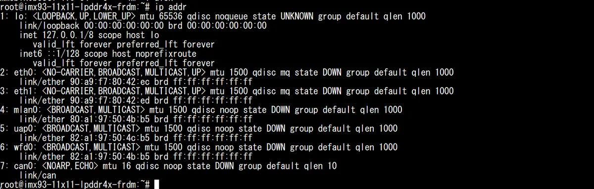
indicates that the system has identified the dual Gigabit Ethernet ports eth0, eth1, the Wi-Fi interface mlan0, the hotspot interface uap0, the Wi-Fi Direct interface wfd0 and the CAN interface can0. Currently, the wired Ethernet port shows NO-CARRIER, and the wireless interface is also in the off state, so no IP address has been obtained temporarily. This indicates that the interface driver has been loaded, but the actual network connection has not been completed yet
7.4 Linux Desktop and System Information
The Linux desktop and GoPoint graphical interface are viewed via an HDMI display. During the actual test, it is only necessary to record display recognition, resolution, mouse operations and basic system information, and there is no need to carry out complex stress testing.
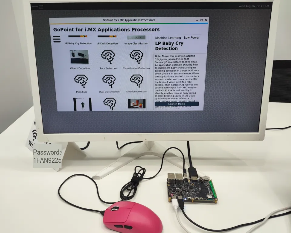
7.5 Full Power-on Video Demonstration
This video mainly introduces the eMMC system pre-installed on the development board at the factory and its basic usage. First, the video demonstrates the complete process of the device booting into the system via eMMC, and explains how to find the COM serial port corresponding to Cortex-A55 on the computer side. Then, it connects to this port through the Tera Term serial port tool to view the serial port logs output during system power-on, booting and entering the operating system in real time, which facilitates users to understand the current running status of the system and troubleshoot problems when booting exceptions occur.
After the system finishes booting, the video also demonstrates how to connect a mouse to the development board and operate the graphical interface with the mouse. In the GoPoint application, users can navigate to the Demo page, select the sample programs pre-provided by the system and run them, so as to quickly experience the graphical interface, multimedia and other hardware functions of the development board. Through this video, users can initially master basic operations such as eMMC system booting, serial port log viewing, and running GoPoint sample programs.
Full power-on video.mp4 183.5 MB
7.6 Official Demo of GoPoint
GoPoint runs in the Linux BSP of the development board, and there is no need to install the Windows version.
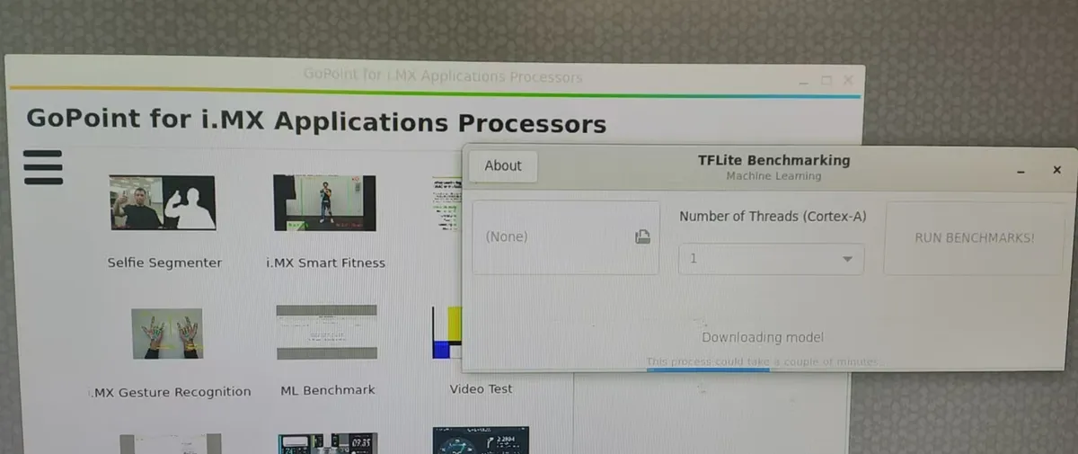
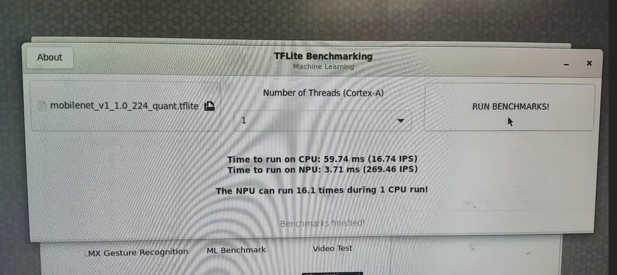
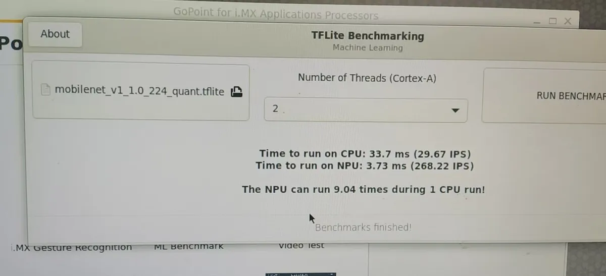
This test uses the ML Benchmark in GoPoint to conduct an inference performance test on the mobilenet_v1_1.0_224_quant.tflite model. The test is configured with Cortex-A55 using 1 thread and 2 threads respectively, and the results are compared with the running results of the onboard NPU.
| Test Configuration | CPU Inference Time | CPU Performance | NPU Inference Time | NPU Performance | NPU vs. CPU |
|---|---|---|---|---|---|
| Cortex-A55 Single Thread | 59.74 ms | 16.74 IPS | 3.71 ms | 269.46 IPS | About 16.1x |
| Cortex-A55 Dual Thread | 33.70 ms | 29.67 IPS | 3.73 ms | 268.22 IPS | About 9.04x |
Wherein, ms refers to the time required to complete one model inference, and a smaller value indicates better performance;IPS refers to the number of inferences that can be completed per second, and a larger value indicates better performance.
It can be seen from the test results that after Cortex-A55 switches from single-thread to dual-thread, the CPU inference time is reduced from 59.74 ms to 33.70 ms, and the inference speed is significantly improved. The inference time of NPU in the two tests basically remains around 3.7 ms, showing relatively stable performance.
The speedup ratio shown in the dual-thread test decreased from 16.1x to 9.04x. This does not mean that the NPU performance degraded; instead, the dual-thread configuration improved the CPU's inference speed, narrowing the gap between the CPU and the NPU. Overall, the inference speed of the NPU is still significantly higher than that of the dual-core Cortex-A55 CPU.
The final test conclusion can be summarized as follows:
The ML Benchmark runs properly. When using the same MobileNet V1 model, dual threads can significantly improve the inference performance of the Cortex-A55, while the inference performance of the NPU remains basically stable under different CPU thread settings. During the test, the inference speed of the NPU is about 9.04 to 16.1 times that of the CPU, which reflects the hardware acceleration capability of the i.MX 93 in lightweight AI inference.
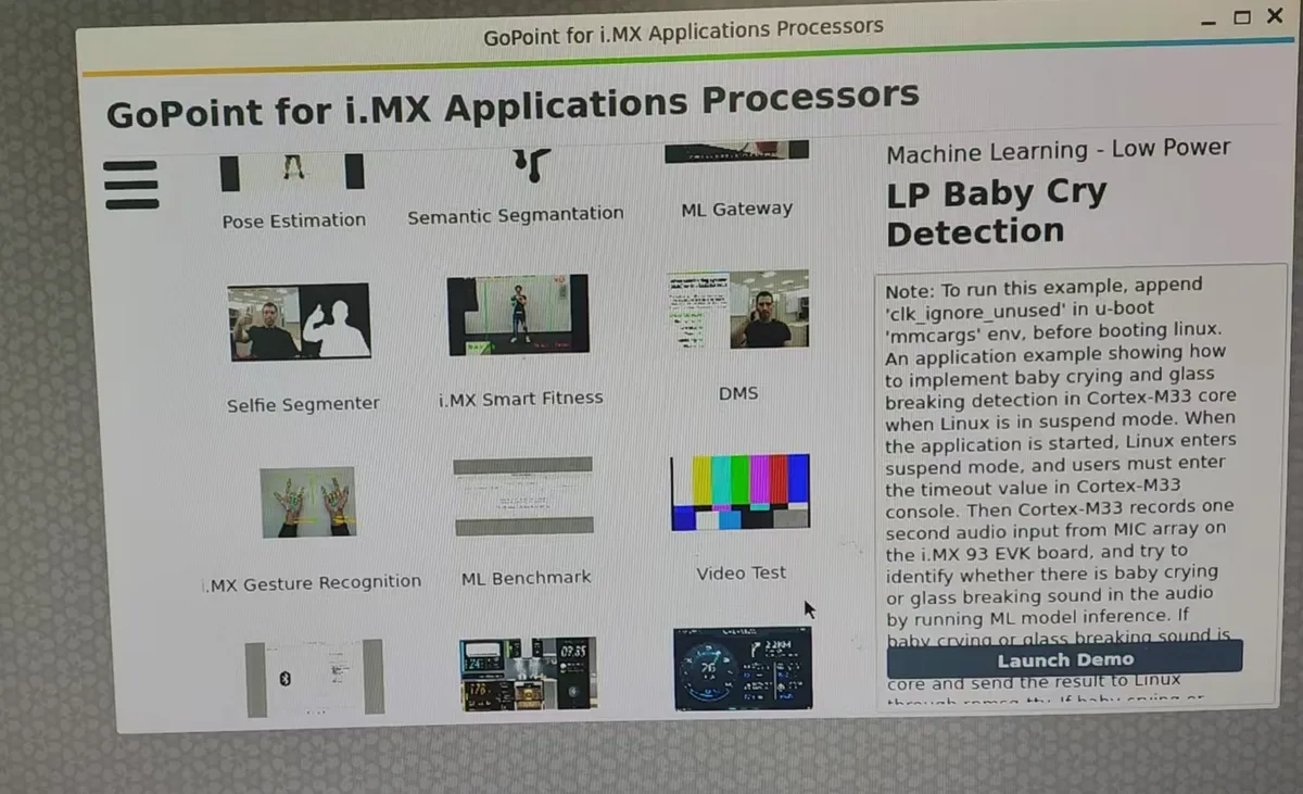
In addition, the factory-shipped eMMC Linux system comes with numerous demos for experimental testing:
VIII. Official Mirror Redeployment
8.1 Official mirror preparation
The supplementary test procedure is to download the NXP official pre-compiled Linux/Yocto mirror, and write it to the microSD card. This way, the factory eMMC system remains untouched while the mirror deployment process can be verified.
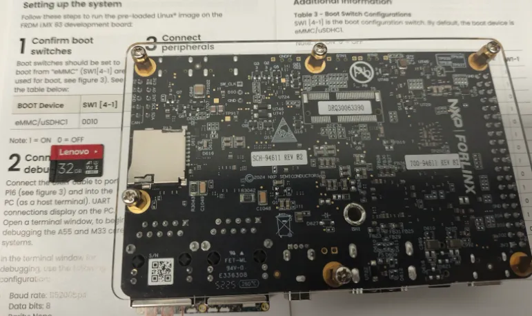
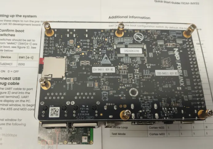
8.2 Enter USB Serial Downloader Mode
- Power off.
- According to the latest official guide and the silkscreen on the board, switch SW1 to the USB Serial Downloader mode.
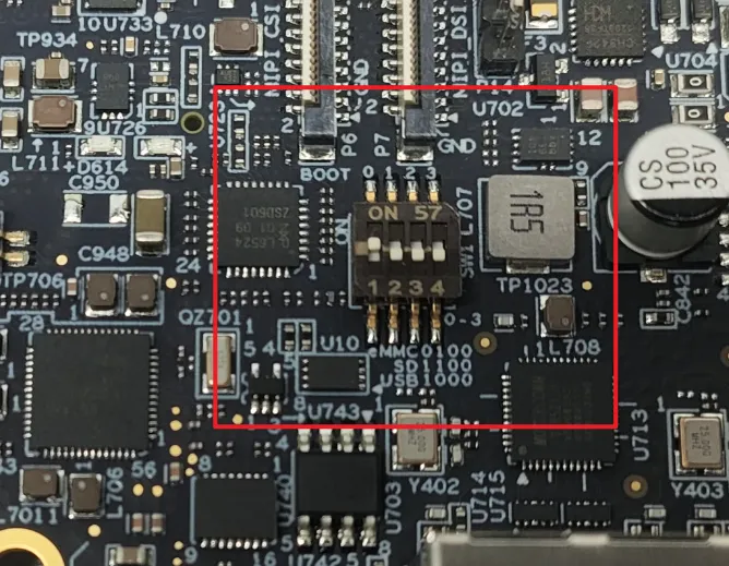
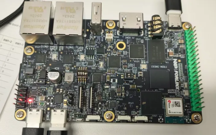
- Connect the USB for download, the debug serial port, and the PD power supply.
8.3 Using UUU to Flash Image to microSD Card
On Windows, open the command line in the directory where UUU and the mirror file are located, and perform the burning according to the actual mirror file name. The command example is as follows:
uuu.exe -b sd_all <actual mirror file name>. wic.zst
My example is as follows:
.\uuu.exe -lsusb

 .\uuu.exe -b sd_all .\imx-boot-imx93-11x11-lpddr4x-frdm-sd.bin-flash_singleboot .\imx-image-full-imx93evk.wi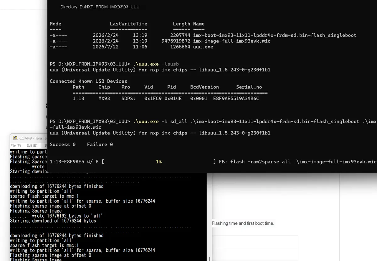
The mirror file name, UUU parameters, and DIP switch direction must be subject to the actually downloaded software package, the latest official guide, and the silkscreen on the board.
8.4 Switch to microSD Boot
- Power off the device after the programming is completed.
- Switch SW1 to the microSD/uSDHC2 boot mode.
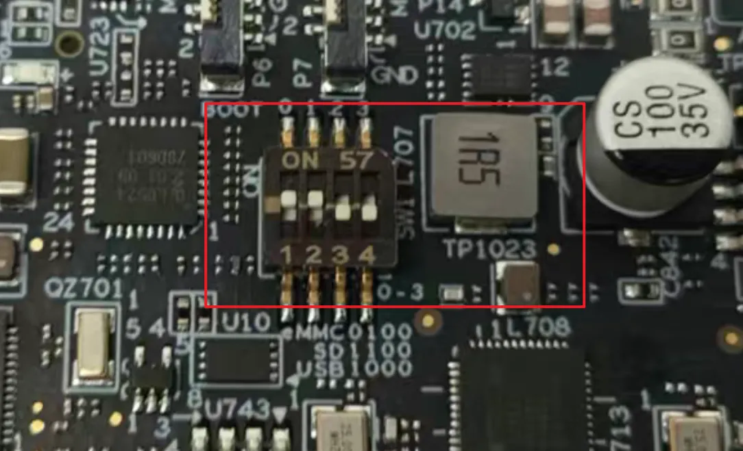
- Re-power the device after inserting the pre-programmed microSD card.
8.5 New System Startup and Function Verification
Verify whether the new system boots successfully via serial port and HDMI, and record the mirror version, UUU version, flashing time consumption and first boot time.

Compared with previous launches:

IX. Simple Function Test
9.1 System Information and Startup Time
For system information testing, only simple commands need to be retained; the focus is on recording the kernel version, distribution information, CPU, memory, storage and network interfaces, and no complex performance benchmarking is required.
uname -a
cat /etc/os-release
lscpu
free -h
df -h
lsblk
ip addr
You can refer to Section 7.1 for the records in the specific startup log.
9.2 HDMI Display
Verify that the HDMI display can properly output the Linux desktop or graphical interface, and check whether mouse operations function normally.
Screen Display and Mouse Control.mp4 25.7 MB
9.3 Wired Network
This mandatory test only verifies the connectivity of one Gigabit Ethernet port. After connecting the network cable, check the IP address and use ping to verify the connectivity of the local area network or gateway.
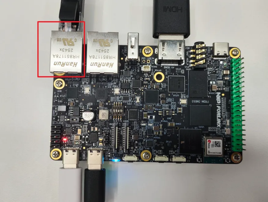
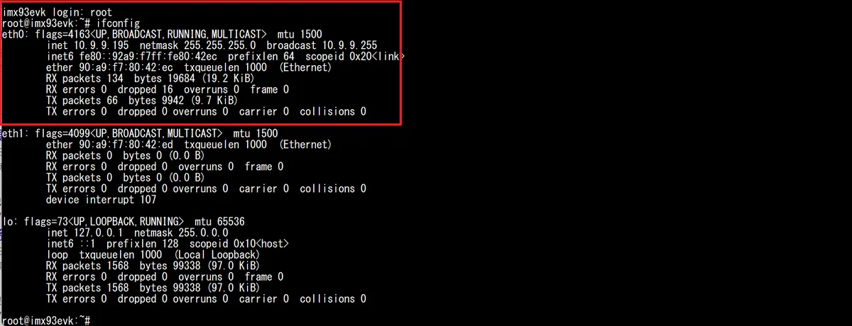
Your current IPv4 address is:
10.9.9.195It belongs to the eth0 network interface:
eth0
inet 10.9.9.195
netmask 255.255.255.0
broadcast 10.9.9.255
Note eth0 is already connected to the network and has obtained an IP address.
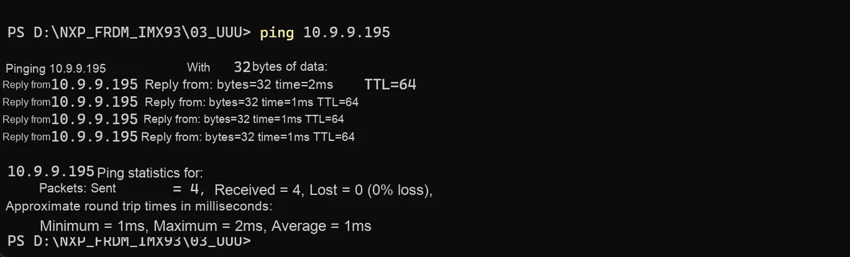
I pinged this address on my computer and found that information can be received.
9.4 Basic Wi-Fi Connection
Wi-Fi STA connection can be tested when conditions permit. If the wireless firmware, driver or network environment is incomplete, only the identification status can be recorded without conducting uAP, throughput stress or complex roaming tests.
The Wi-Fi Client interface of FRDM-i.MX93 is typically named mlan0
- Scan Wi-Fi
Execute in sequence:
modprobe moal mod_para=nxp/wifi_mod_para.confExecute after waiting for a few seconds:
ifconfig mlan0 upThen scan for nearby Wi-Fi:
iw dev mlan0 scanThe official NXP FRDM-i.MX93 guide also follows the procedure of "loading the
moaldriver → enablingmlan0→ usingiwfor scanning".If you just want to simply check the Wi-Fi name and signal strength, you can run the following command:
iw dev mlan0 scan | grep -E "SSID:|signal:"The output will be similar to:
signal: -42.00 dBm
SSID: MyWiFi

signal: -67.00 dBm
SSID: Phone_Hotspot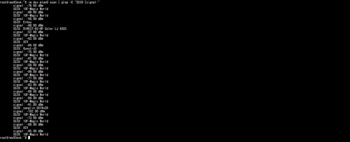
- Connect to Wi-Fi
Using ConnMan is the most convenient way to connect, and the NXP i.MX Linux mirror also recommends managing Wi-Fi via
connmanctl.Execute in sequence:
ifconfig mlan0 upGenerate temporary Wi-Fi configuration:
wpa_passphrase "10F-Magic World" '10FMW@2025' | sed '/^[[:space:]]*#psk=/d' > /tmp/wpa-magic.conf
Restrict configuration file permissions:
chmod 600 /tmp/wpa-magic.confConnecting:
wpa_supplicant -B -i mlan0 -D nl80211 -c /tmp/wpa-magic.conf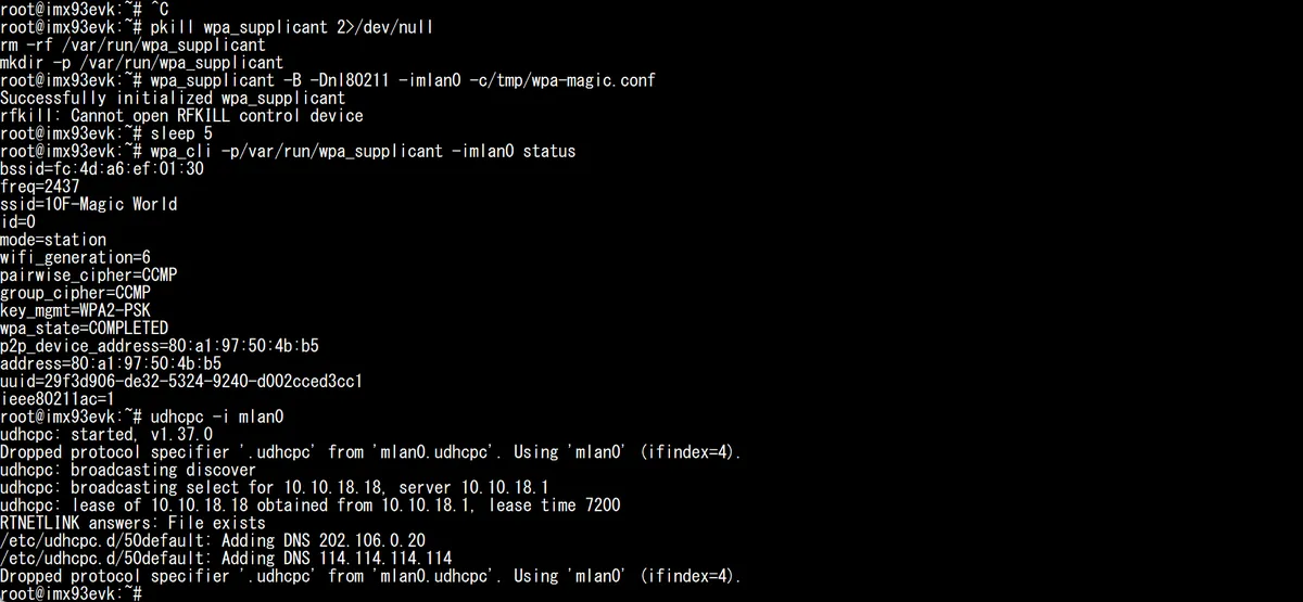
Wait for a few seconds and then check the connection status:
wpa_cli -i mlan0 statusNormal expected result:
ssid=10F-Magic World
wpa_state=COMPLETED
- Test Wi-Fi
Then obtain the IP address:
udhcpc -i mlan0
Check the Wi-Fi IP address:
ip -4 addr show mlan0
Test Wi-Fi network connection:
ping -I mlan0 -c 4 8.8.8.8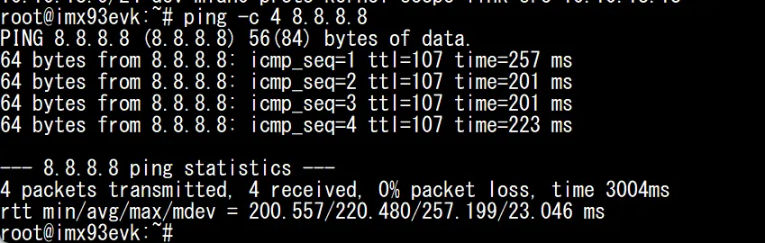
X. Introduction to Other Capabilities and Software Ecosystem
10.1 Cortex-M33 Heterogeneous Processing
The i.MX 93 integrates a Cortex-M33 core, which can be deployed for real-time control, low-power tasks or coprocessing operations. This evaluation only covers its positioning, and there is no requirement to build the M33 firmware separately.
10.2 Bluetooth LE
Bluetooth LE is connected to the IW612 via UART by default. If time permits, basic scanning can be performed; connection pairing, throughput and long-term stability are not listed as mandatory tests.
10.3 802.15.4 and OpenThread
802.15.4 is accessed via SPI by default, and OpenThread/OTBR relies on supporting mirror and software components. This document introduces them as reference materials, and there is no requirement to build a complete Thread network.
XI. Practical Experience and Summary
The following evaluation is mainly based on official hardware materials and software support conditions; the actual ease of use, boot speed, system stability and Demo running effect need to be supplemented based on the actual test results after the development board arrives.
11.1 Advantages
- The hardware resources feature wide coverage, with 2 GB LPDDR4X, 32 GB eMMC, dual Gigabit Ethernet ports, tri-mode wireless, HDMI, MIPI, CAN and expansion interfaces all integrated on a compact board.
- The factory-default eMMC comes preinstalled with Linux BSP, which is ideal for quick power-on verification.
- The GoPoint Demo route is suitable for visual demonstrations, as it can intuitively showcase the AI and multimedia capabilities of the i.MX 93.
11.2 Application Scenarios
- Linux edge gateways, industrial networking prototypes, and HMI demonstrations.
- Lightweight AI inference, GoPoint Demo demonstration, and NPU introductory verification.
- Pre-research on product solutions featuring dual Ethernet ports, wireless tri-mode, CAN, and display/camera interfaces.
11.3 Comprehensive Evaluation
The FRDM i.MX 93 is better suited as the first board for i.MX 93 product verification: it has complete enough hardware resources, the software path is supported by the official BSP, and you can focus on the factory system, serial port logs, HDMI, GoPoint, one Ethernet port and microSD mirror deployment when getting started. Complex peripherals and full Yocto compile can be left for the subsequent productization phase.
XII. Common Issues About Burning Mirror
Timeout while burning mirror
When burning the TF card with UUU, it stops at M33 prepare ok and prompts a timeout
When using the old version LF_v6.6.36-2.1.0 mirror to flash the FRDM-i.MX93, the serial port log stops at:
M33 prepare ok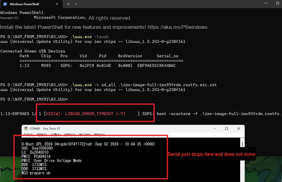
This is usually not a problem with the USB cable or the UUU tool; instead, the DDR configuration of the old version Bootloader may not be compatible with newer batches of FRDM-i.MX93, causing the development board to fail to enter the subsequent Fastboot flashing phase.
The solution is to download a newer official BSP:
Visit NXP's official BSP website:
Embedded Linux for i.MX Application Processors
Find the new version mirror
L6.18.2-1.0.0_MX93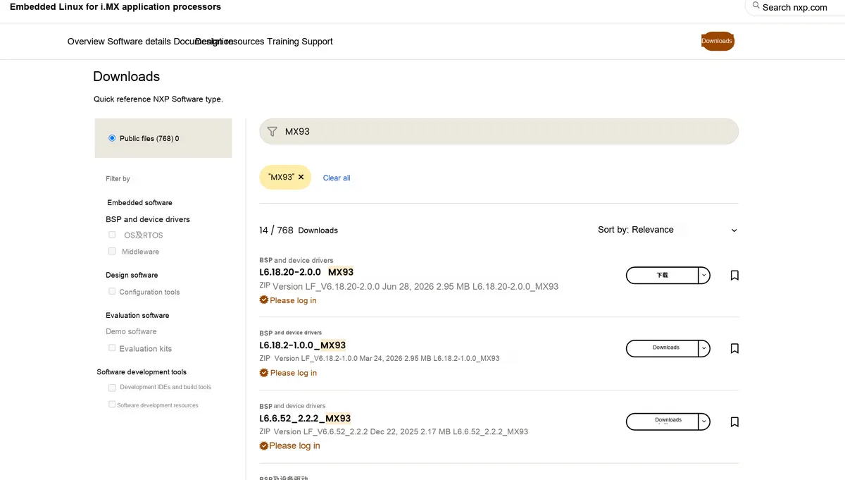
After decompression, select the FRDM-i.MX93 dedicated Bootloader whose file name contains frdm and lpddr4x, then use sd_all to write the mirror to the TF card.
This failure occurred during the temporary boot phase, and sd_all was used, so the original eMMC system will not be overwritten.
13. References
i.MX93 Block Diagram.pdf 94 KB
IMX93 Applications Processors Data Sheet.pdf 2.5 MB
FRDM i.MX 93 development board.pdf 957 KB
UM12181_FRDM-IMX93 Board User Manual.pdf 10.3 MB
i.MX Linux Release Notes.pdf 532 KB