Contents
- I. Module Introduction
- II. Introduction to Major Chips
- 2.1 Chip Overview
- 2.2 Pin Definition
- 2.3 Functional Block Diagram
- 2.4 Performance Parameters
- 2.5 Reference Circuit
- 2.6 Chip Configuration
- 2.7 Communication Interfaces and Related Protocols
- 2.8 PCB Routing Precautions
- III. Circuit Engineering
- 3.1 Circuit Source Engineering
- 3.2 Module Usage Instructions
- 3.3 Application Experiment
- IV. Drivers
- 5. BOM & Recommended Alternative Parts
- VI. Revision History
- VII. Relevant Materials
- 7.1 Chip Datasheet
- 7.2 Unique Icons for PCB Silkscreen
I. Module Introduction
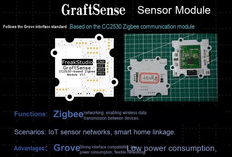
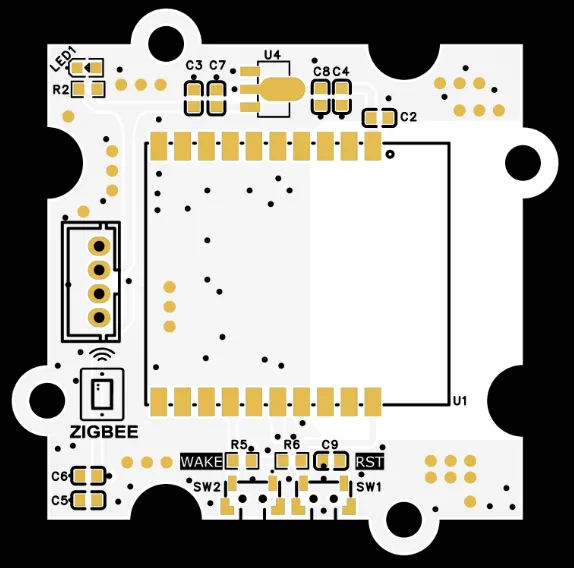
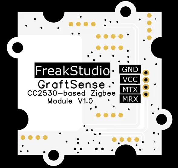
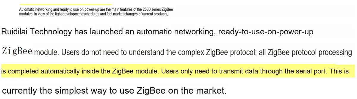
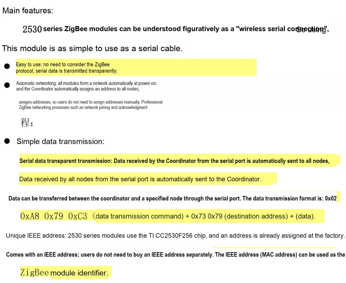
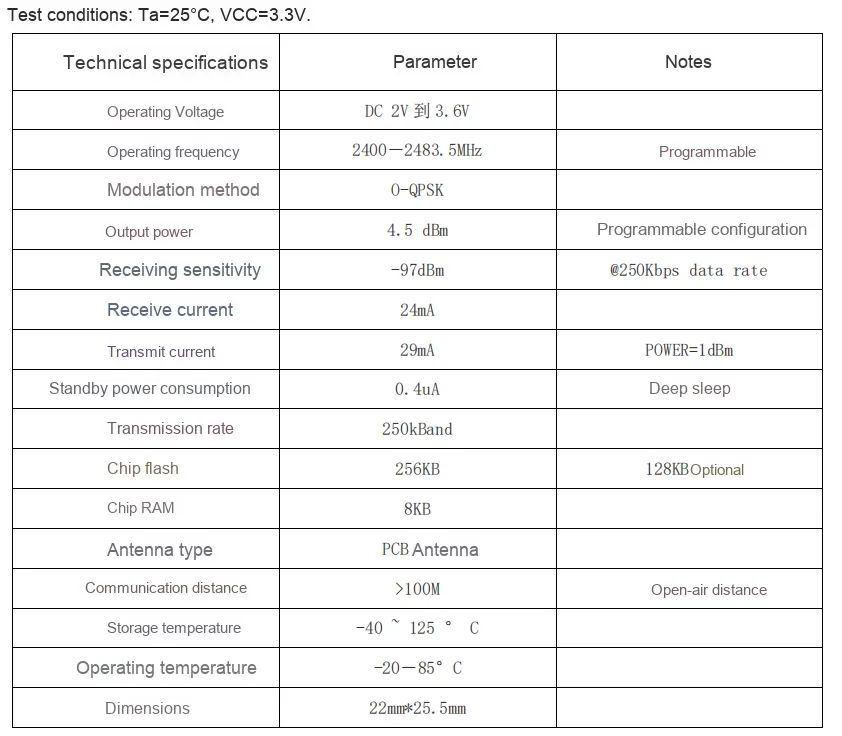
ZigBee communication module based on CC2530 takes CC2530 chip as the core, supports IEEE 802.15.4 and ZigBee protocols, operates at a voltage of 2 - 3.6V, with a receiving current of 24mA, a transmitting current of 29mA (1dBm), a transmission rate of 250kbps, and an operating temperature range of -40~85℃. It is equipped with a UART interface, which can realize low-power short-distance wireless communication, and is suitable for scenarios such as smart homes, industrial Data Acquisition, and wireless sensor networks.
II. Introduction to Major Chips
Here, we adopt a CC2530 series-based ZigBee wireless data transmission module CC2530-A1.
2.1 Chip Overview
2.2 Pin Definition
2.3 Functional Block Diagram
None.
2.4 Performance Parameters
2.5 Reference Circuit
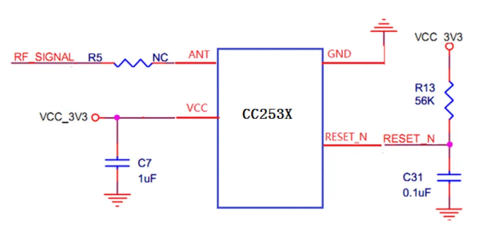
R13 (a 56 kΩ resistor) has one terminal connected to VCC_3V3, and the other terminal connected in series with C31 (a 0.1 μF capacitor) to ground, while also connected to the RESET_N pin of the CC253X.
R13 and C31 form a reset circuit with the following operating principle: The RESET_N pin of the CC253X chip is active low; when the pin is pulled low, the chip enters a reset state and stops executing programs. As the capacitor C31 gradually charges up, the voltage at the RESET_N pin rises steadily to VCC_3V3 (high level). Once the voltage exceeds the chip's reset threshold, the reset signal is released and the chip resumes normal operation.
2.6 Chip Configuration
This module is of Plug and Play type, requiring no hardware configuration or software register setup. ZigBee performs communication to exchange data with other devices via the serial port.
2.7 Communication Interfaces and Related Protocols

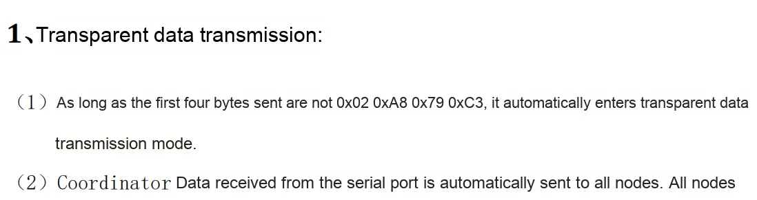
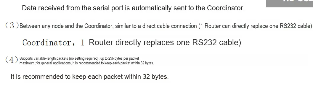
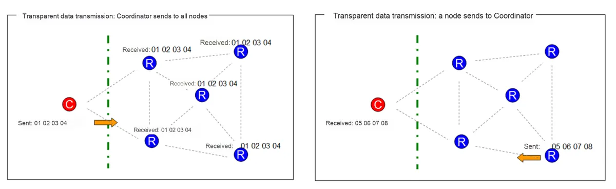
2.7.1 Introduction to Data Transparent Transmission
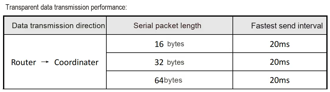
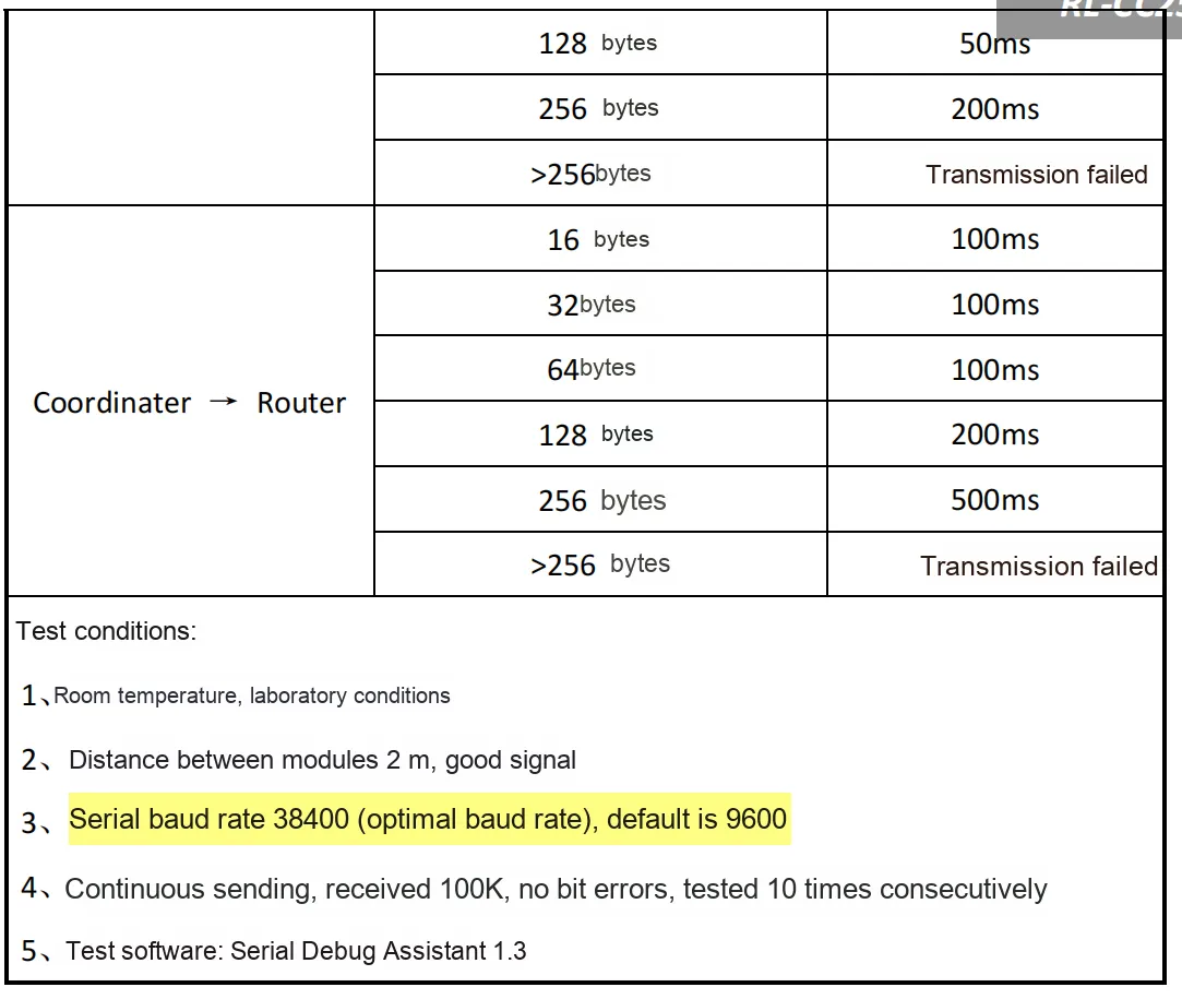
Transparent data transmission is similar to serial port pass-through. It supports variable-length packets, with a maximum length ≤256 bytes; a length ≤32 bytes is recommended.
2.7.2 Introduction to Peer-to-Peer Data Transmission

- The
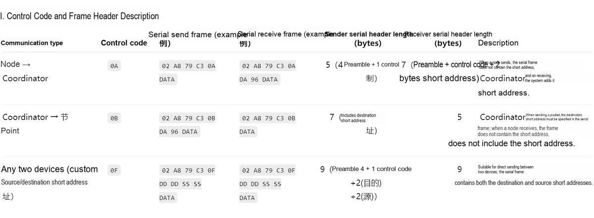
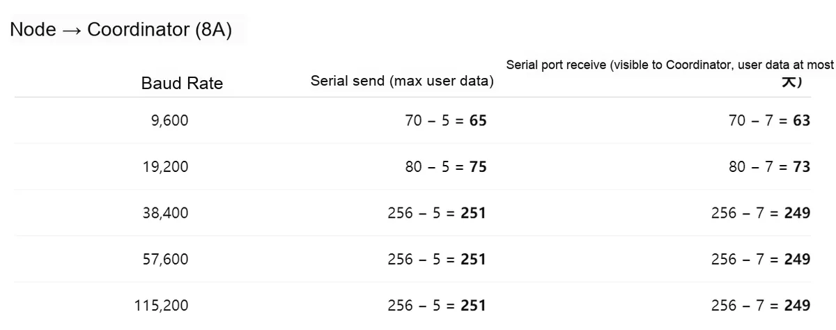
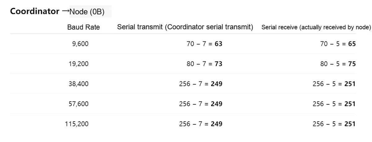
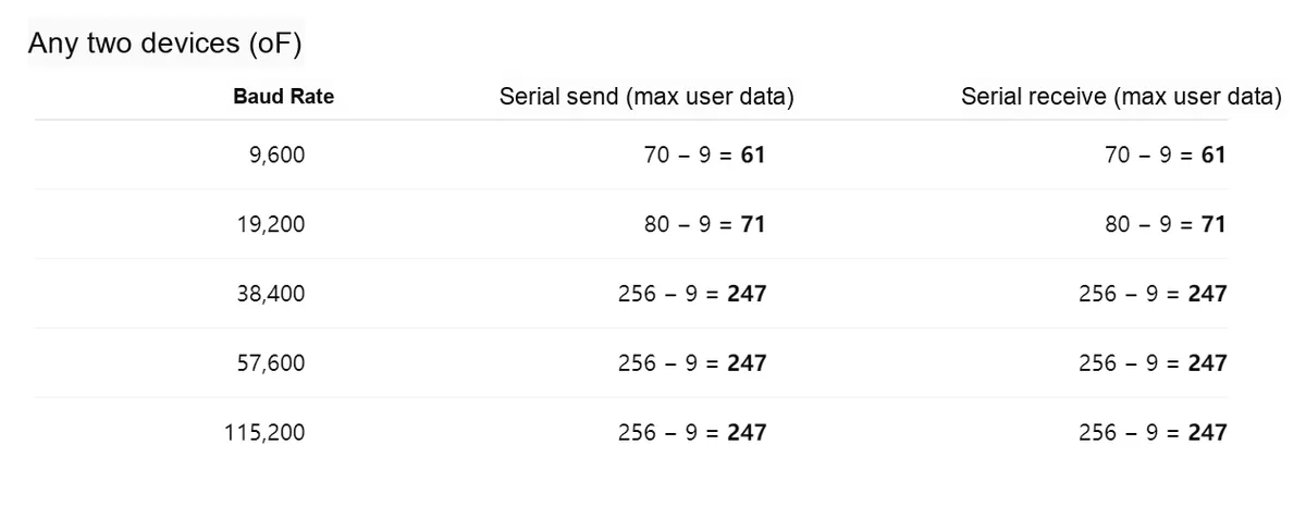
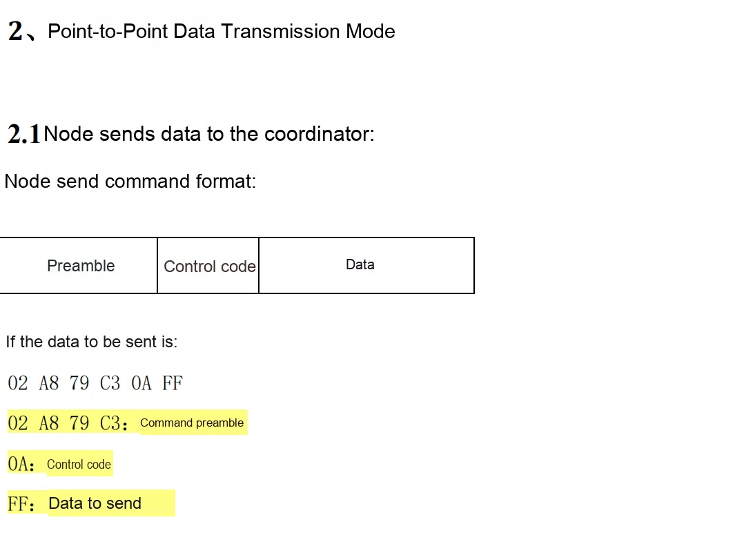
FFin the example is just sample data (1 byte), and it does not mean that the protocol limits the transmission to only 1 byte. - Actually, user data is of variable length, and its length is limited by "the maximum single-packet length corresponding to the baud rate" and the frame header length (see the previous table).
- Recommended engineering practice: each packet ≤ 32 bytes (stable and with good compatibility).
2.7.2.1 Node to Coordinator
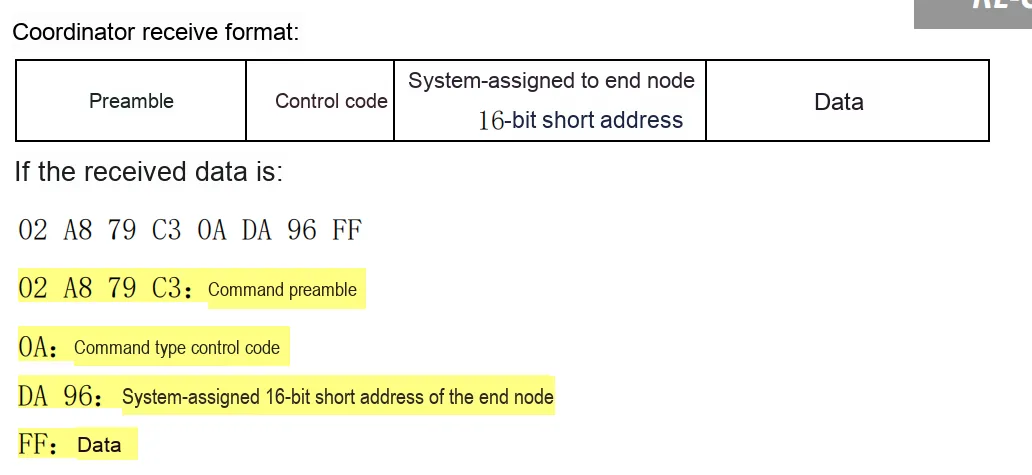
2.7.2.2 Coordinator to Node
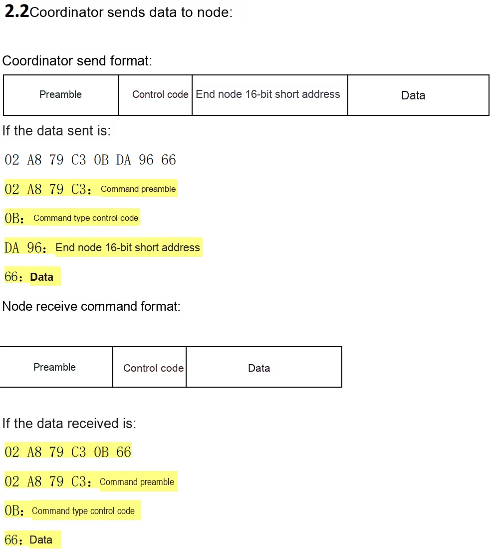
2.7.2.3 Node to Node
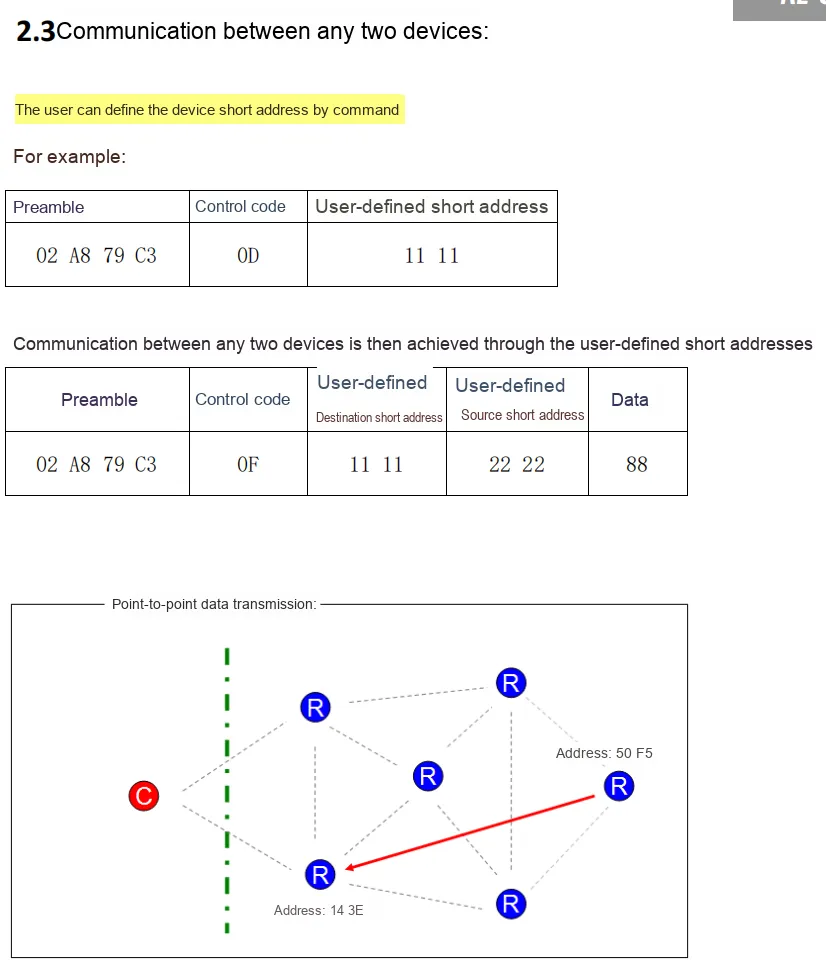
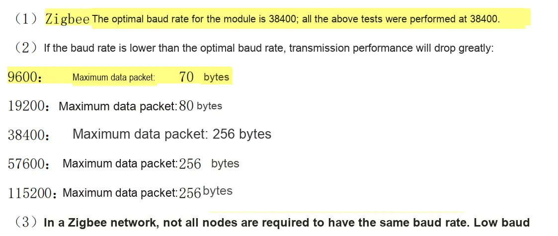
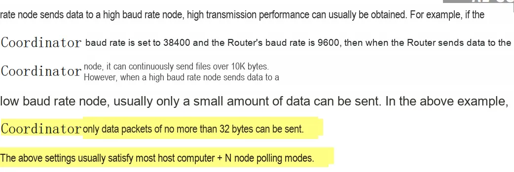
2.7.3 Specific Instructions
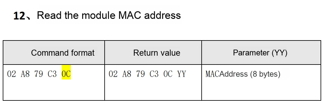
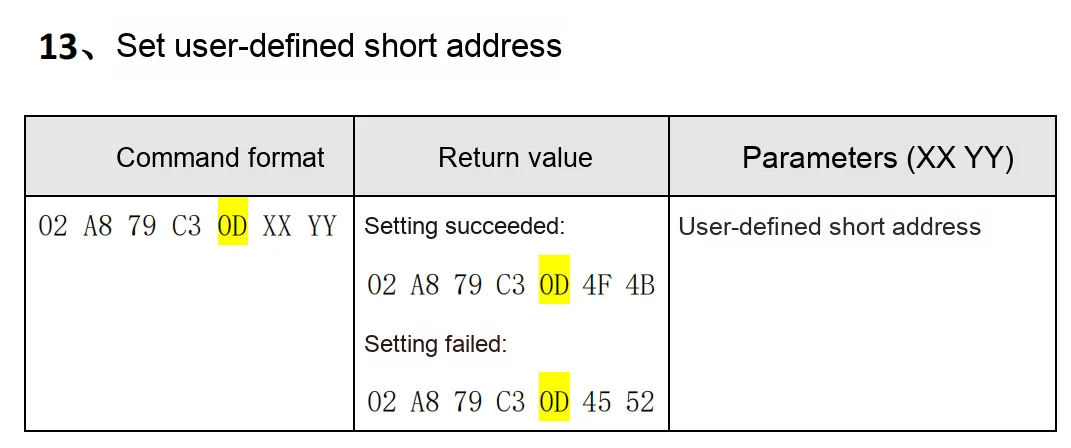
2.7.3.1 Basic Settings and Query Commands
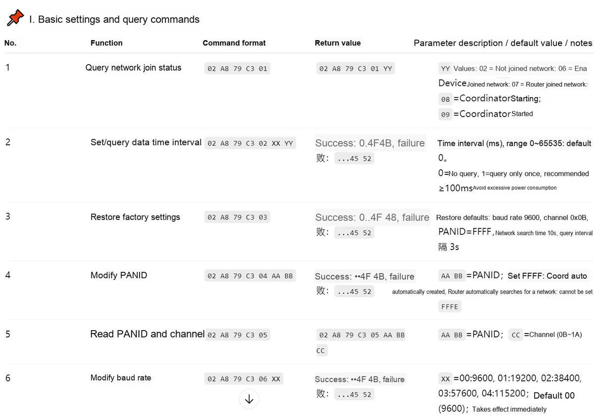
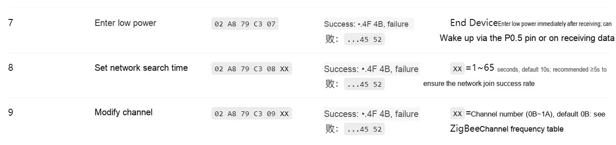
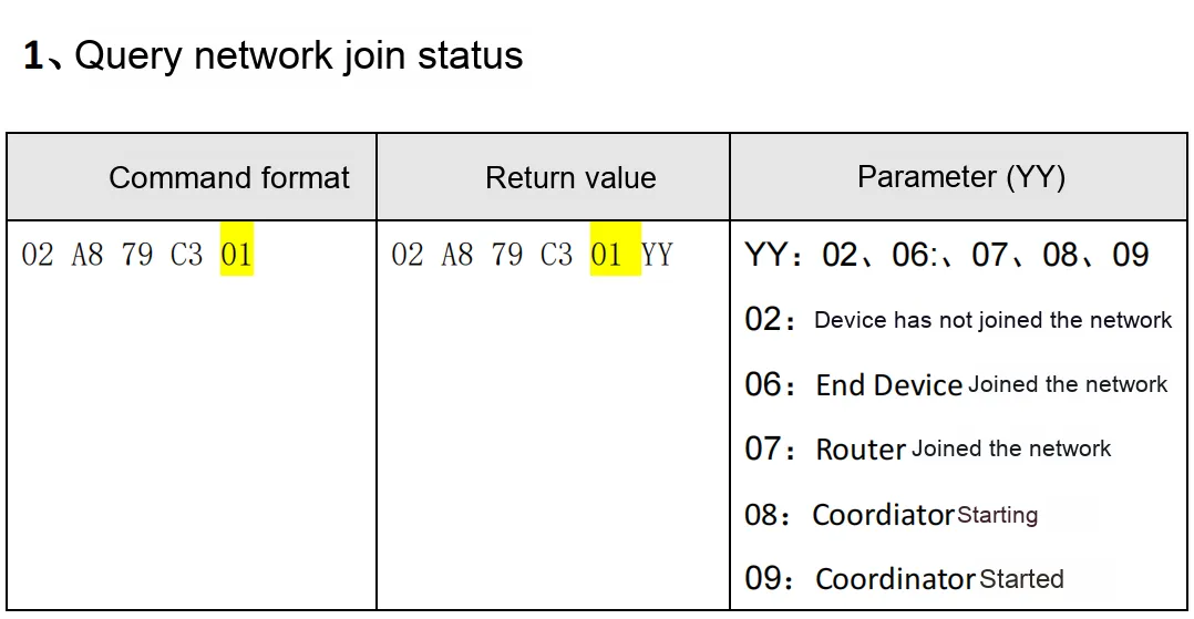
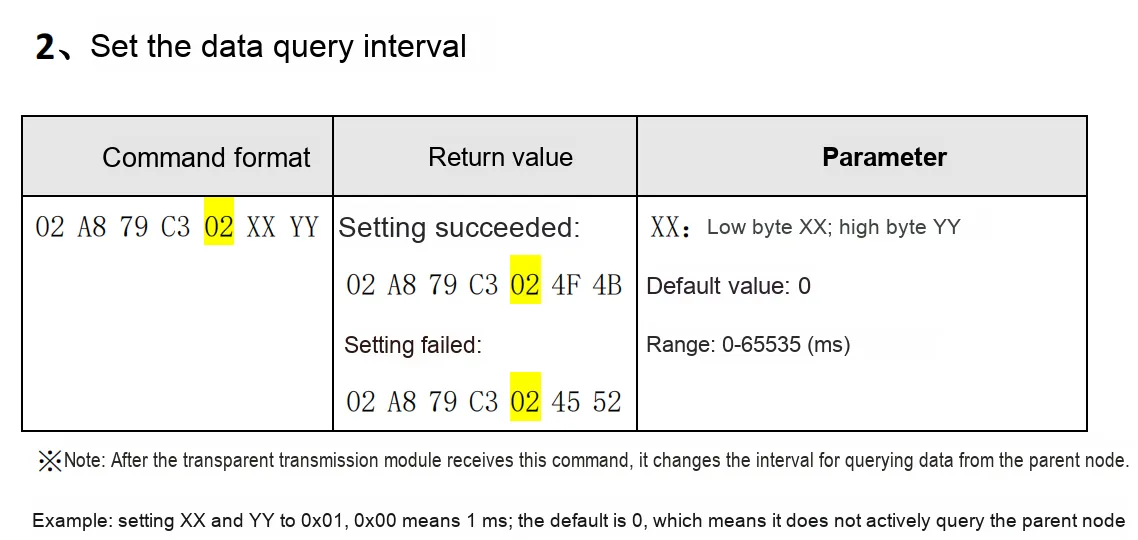

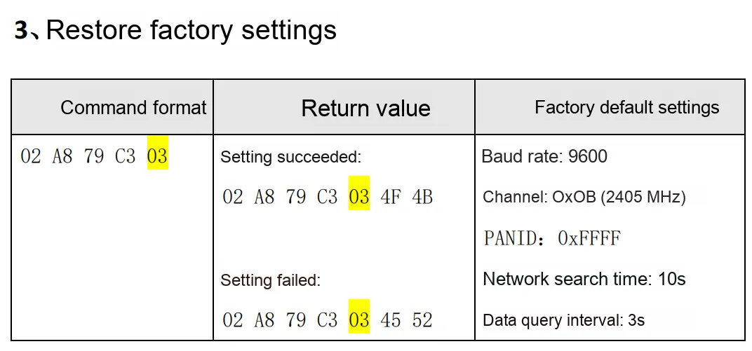
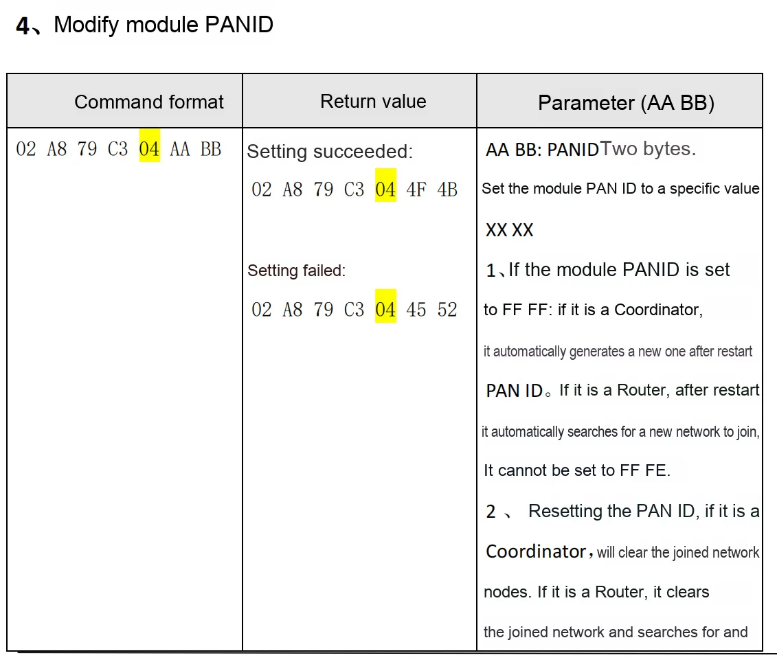
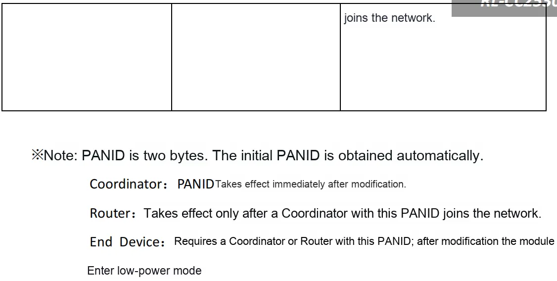
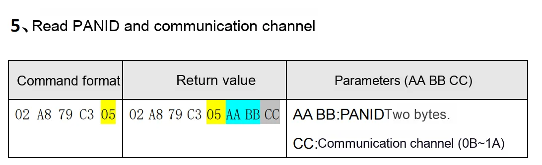
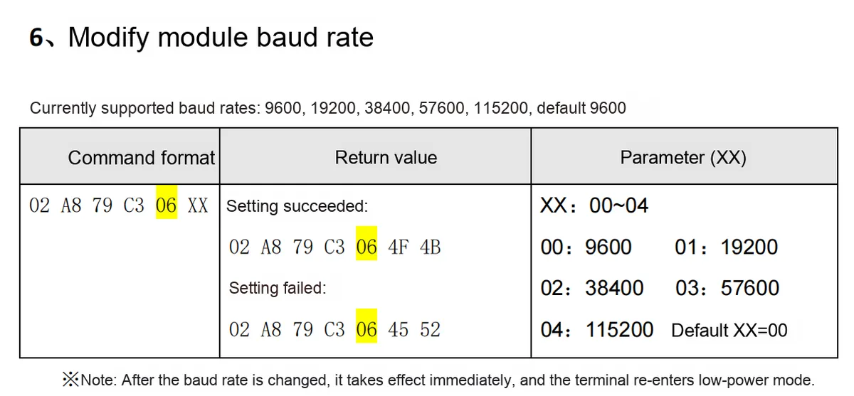
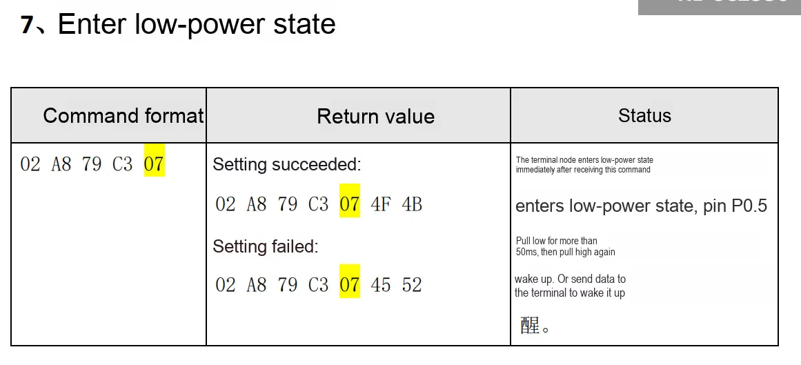
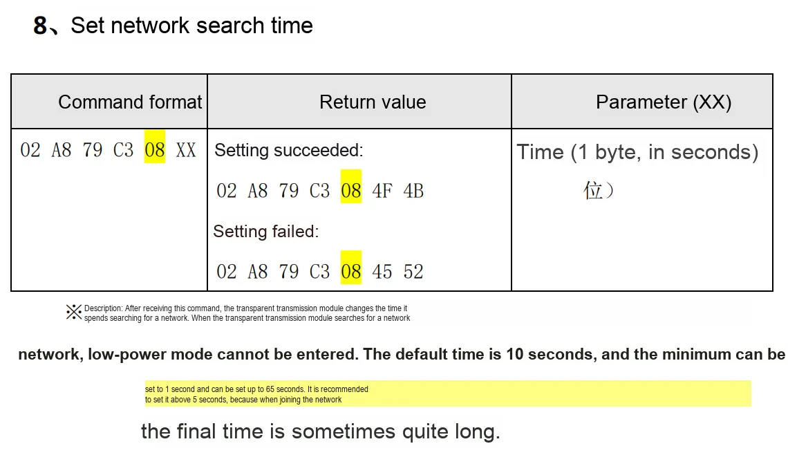
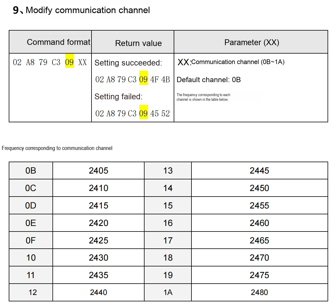
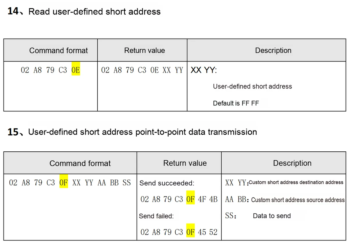
2.7.3.2 Instructions Related to Peer-to-Peer Communication
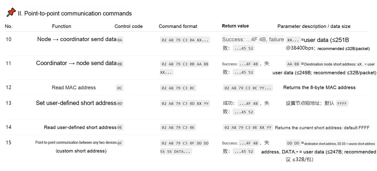
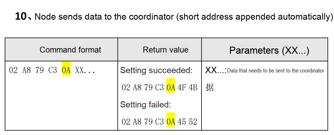
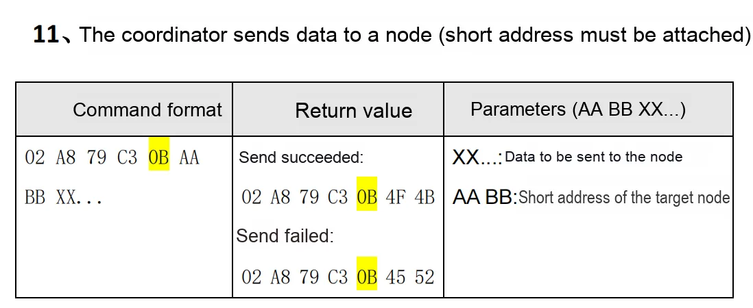
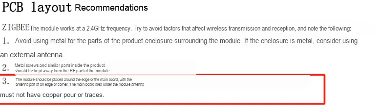
2.8 PCB Routing Precautions
III. Circuit Engineering
3.1 Circuit Source Engineering
To obtain the source project of the circuit, please follow the official account [Freak Embedded]
3.2 Module Usage Instructions
The schematic diagram of this module is shown below:
SCH_Schematic1_CC2530-Based Zigbee Communication Module-V1.0.0_2025-10-24.pdf 2.2 MB
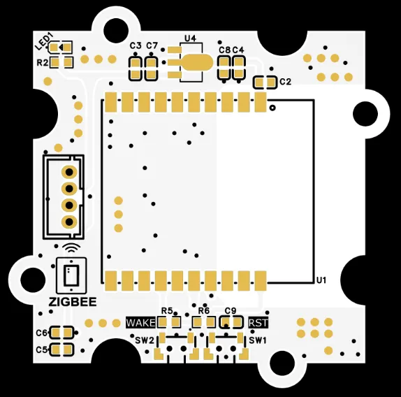
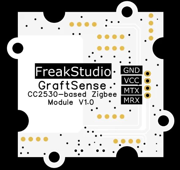
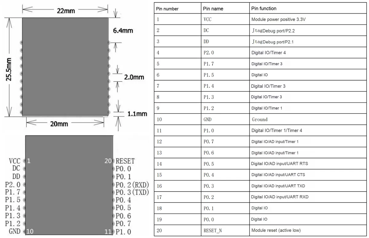
This module provides a serial port UART interface MRX and MTX: here M stands for master, which means the MCU 's RX corresponds to the module' s TX.
Of particular note is that when using this module, MRX is directly connected to the RXD pin of the MCU's serial port, and MTX is directly connected to the TXD pin of the MCU's serial port; be sure not to cross-connect them.
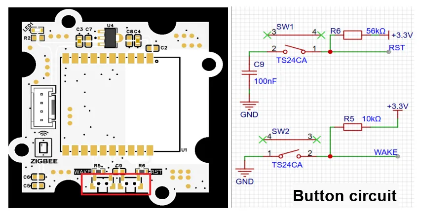
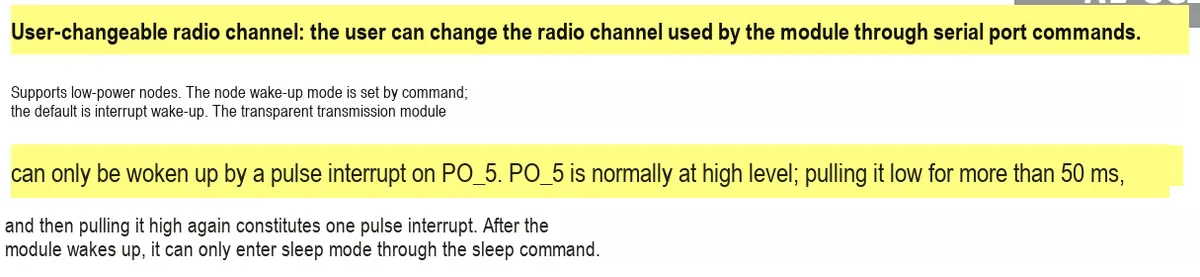
Functions of the two tact switches: SW1 is the module reset button, the module is reset at low level, SW2 serves as the interrupt wake-up pin.
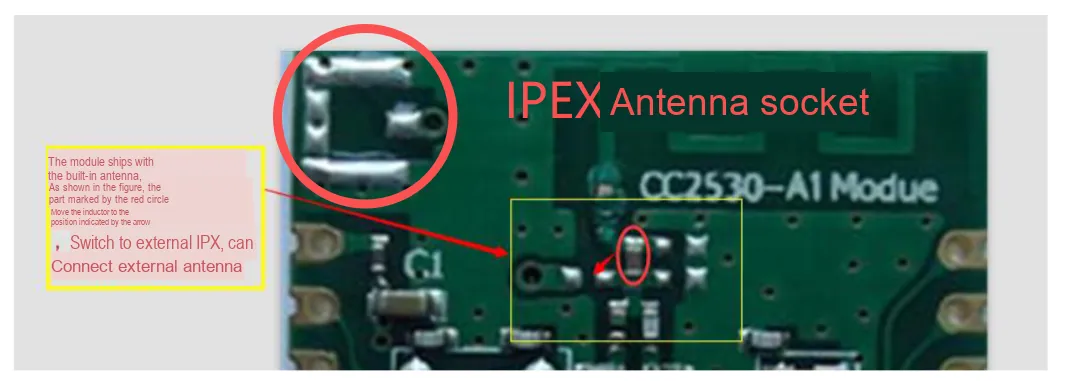
Switching Method for External Antenna of Module:
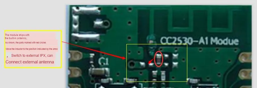
When switching to an external antenna, it is necessary to solder the IPEX connector housing to the IPEX pad located in the upper left corner:
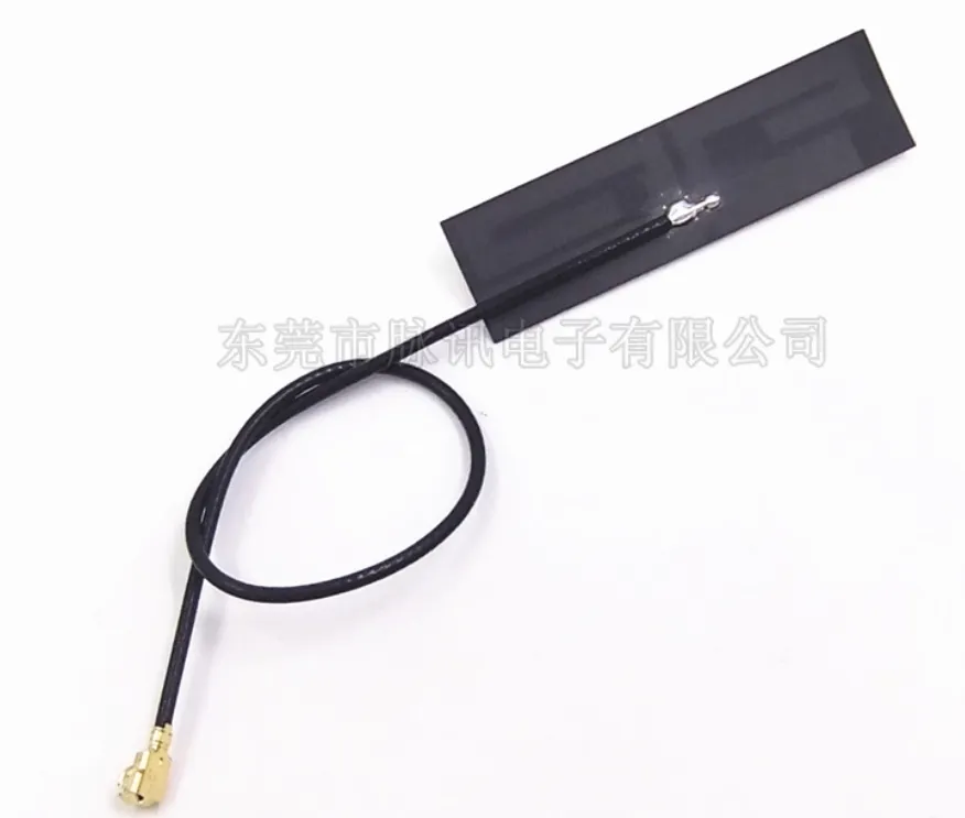
Then you can use an antenna with the following IPEX interface:
3.3 Application Experiment
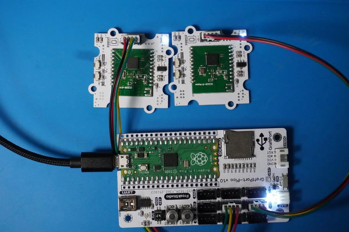
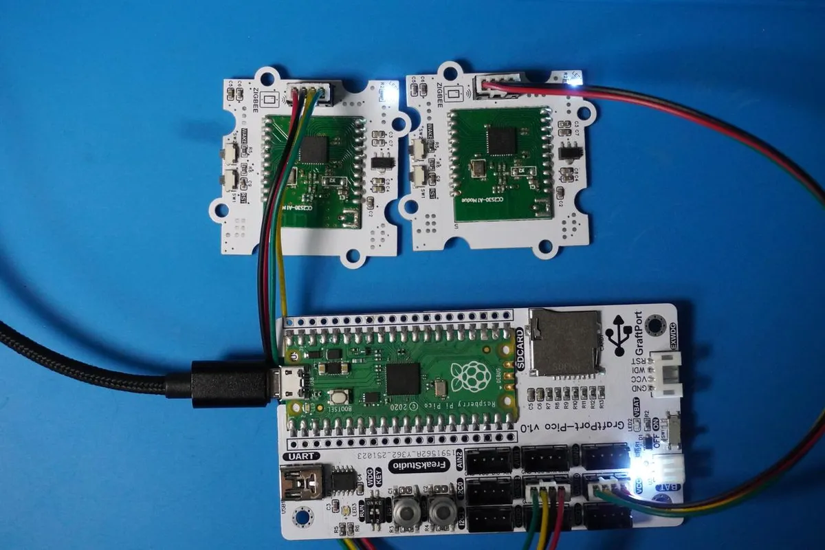
Here, we use the GraftPort-RP2040 development board for testing, and we adopt two CC2530-based Zigbee communication modules (acting as a router and a coordinator respectively) to communicate with the main controller via the UART interface.
3.3.1 Transparent Transmission Experiment
Here, we first use the HY2.0-4P cable to connect the module to the GraftPort-RP2040 development board's UART0 and UART1 interfaces:
The module connections are shown in the following table:
Router Zigbee:
Development Board Pins | Module Pins | Description |
Pin 16 |
|
|
Pin 17 |
|
|
Coordinator Zigbee:
Development Board Pins | Module Pins | Description |
Pin 8 |
|
|
Pin 9 |
|
|
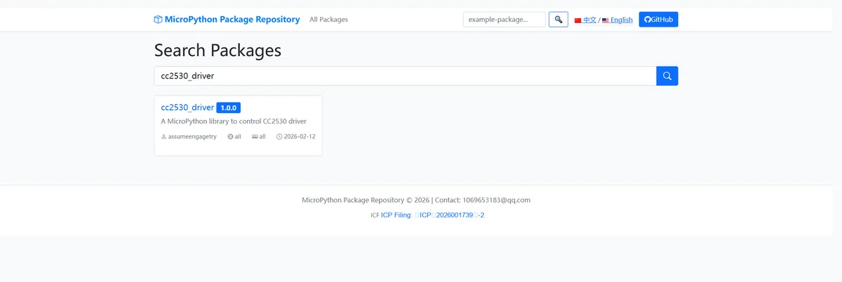
Here, we need to search for the relevant driver packages on uPyPI: https://upypi.net/zh/
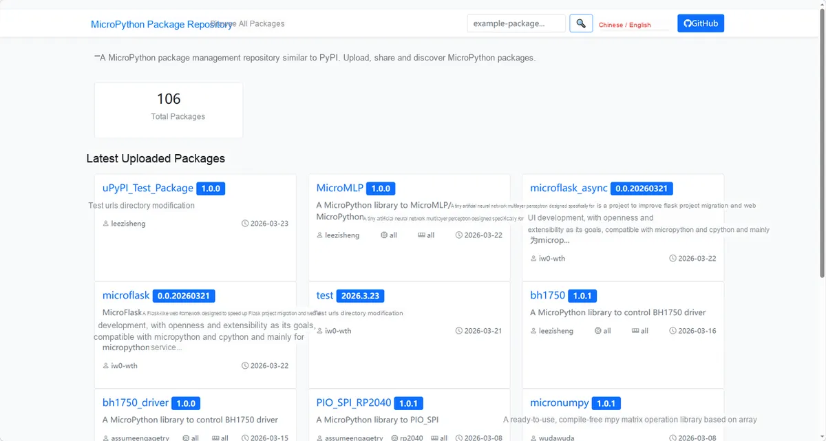
Enter cc2530_driver to search, and the following will be displayed:
Click to copy the local installation command:
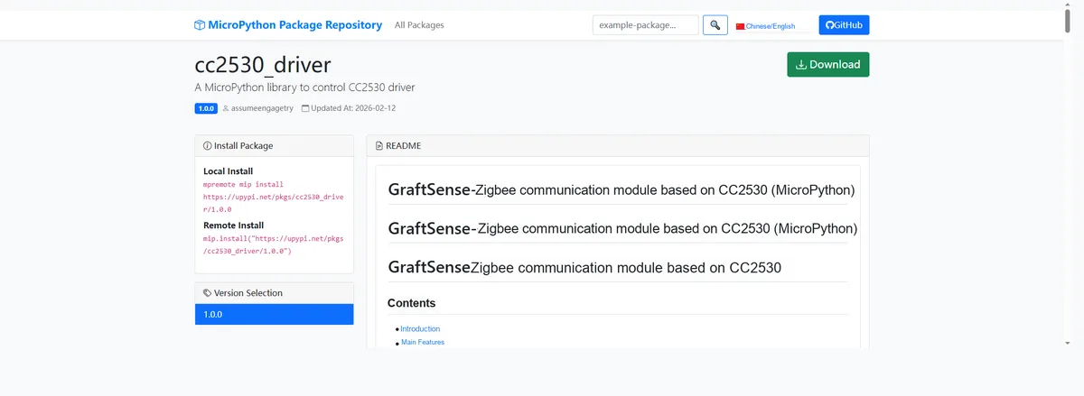
Here, we can use the mip tool to import module driver library code. Below are the usage commands for the mpremote tool:
mpremote mip install github:FreakStudioCN/GraftSense-Drivers-MicroPython/communication/cc2530_driverImport the CC2530 Zigbee driver - MicroPython driver code, then in the REPL call transparent. py
# Import file as the main program
import transparent
transparent. py The content is as follows:
# Python env   : MicroPython v1.23.0
# -*- coding: utf-8 -*-
# @Time    : 2025/9/5 10:11 PM
# @Author  : ben0i0d
# @File    : transparent.py
# @Description : cc253x_ttl transparent transmission test file

# ======================================== Import Modules =========================================

# Import hardware-related modules
import time
from machine import UART, Pin
# Import the third-party driver module
from cc253x_ttl import CC253xTTL

# ======================================== Global Variables ============================================

# ======================================== Functions ============================================

# ======================================== Custom Classes =============================================

# ======================================== Initialization configuration ===========================================

# Power-on delay of 3 s
time.sleep(3)
# Print debug information
print("FreakStudio: cc253x_ttl transparent test")

# Declare serial port instance
uart0 = UART(0, baudrate=9600, tx=Pin(16), rx=Pin(17))
uart1 = UART(1, baudrate=9600, tx=Pin(8), rx=Pin(9))

# Coordinator
cor = CC253xTTL(uart0)
# Router
env = CC253xTTL(uart1)

# Set the router and coordinator to the same PANID
while cor.read_status() is None:
    pass
while env.read_status() is None:
    pass

# Get the coordinator PANID and channel
pamid, ch = cor.read_panid_channel()
print(f"cor:pamid:{pamid},channel:{ch}")

while env.set_panid(int(pamid,16)) is False:
    pass
while env.set_channel(int(ch,16)) is False:
    pass

# Output the router PANID and channel
time.sleep(0.5)
pamid, ch = env.read_panid_channel()
print(f"env:pamid:{pamid},channel:{ch}")

# ========================================  Main Program  ===========================================

while True:
    # Router sends
    cor.send_transparent("Here is transparent")
    time.sleep(0.5)

    # Coordinator receives and outputs
    mode, data, addr1, addr2 = env.recv_frame()
    print(f" Coordinator Received Data:")
    print(f"   Mode: {mode}")
    print(f"   Data: {data}")
    print(f"   Address 1: {addr1}")
    print(f"   Address 2: {addr2}")
    time.sleep(1)
REPL outputs the following:
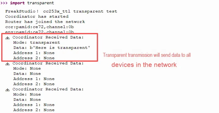
It can be seen that the two modules can transparently transmit data to each other.
3.3.2 Node-to-Coordinator Transmission Experiment
Here, we first use the HY2.0-4P cable to connect the module to the GraftPort-RP2040 development board's UART0 and UART1 interfaces:
The module connections are shown in the following table:
Router Zigbee:
Development Board Pins | Module Pins | Description |
Pin 16 |
|
|
Pin 17 |
|
|
Coordinator Zigbee:
Development Board Pins | Module Pins | Description |
Pin 8 |
|
|
Pin 9 |
|
|
Import the CC2530 Zigbee driver - MicroPython driver code, then call REPL to invoke node_to_coord.py
# Import file as the main program
import node_to_coord
node_to_coord.py The content is as follows:
# Python env   : MicroPython v1.23.0
# -*- coding: utf-8 -*-
# @Time    : 2025/9/5 10:11 PM
# @Author  : ben0i0d
# @File    : main.py
# @Description : cc253x_ttl node_to_coord test file

# ======================================== Import Modules =========================================

# Import hardware-related modules
import time
from machine import UART,Pin
# Import the third-party driver module
from cc253x_ttl import CC253xTTL

# ======================================== Global Variables ============================================

# ======================================== Functions ============================================

# ======================================== Custom Classes =============================================

# ======================================== Initialization configuration ===========================================

# Power-on delay of 3 s
time.sleep(3)
# Print debug information
print("FreakStudio: cc253x_ttl node_to_coord test")

# Declare serial port instance
uart0 = UART(0, baudrate=9600, tx=Pin(16), rx=Pin(17))
uart1 = UART(1, baudrate=9600, tx=Pin(8), rx=Pin(9))

# Coordinator
cor = CC253xTTL(uart0)
# Router
env = CC253xTTL(uart1)

# Set the router and coordinator to the same PANID
while cor.read_status() is None:
    pass
while env.read_status() is None:
    pass

# Get the coordinator PANID and channel
pamid,ch=cor.read_panid_channel()
print(f"cor:pamid:{pamid},channel:{ch}")
while env.set_panid(int(pamid,16)) is False:
    pass
while env.set_channel(int(ch,16)) is False:
    pass

# Output the router PANID and channel
time.sleep(0.5)
pamid,ch=env.read_panid_channel()
print(f"env:pamid:{pamid},channel:{ch}")

# ========================================  Main Program  ===========================================

while True:
    # Router sends to the coordinator
    env.send_node_to_coord("node_to_coord")
    time.sleep(0.5)

    # Coordinator receives and outputs
    mode, data, addr1, addr2 = cor.recv_frame()
    print(f" Coordinator Received Data:")
    print(f"   Mode: {mode}")
    print(f"   Data: {data}")
    # node_to_coord returns the coordinator address addr1
    print(f"   Address 1: {addr1}")
    print(f"   Address 2: {addr2}")
    time.sleep(1)
REPL outputs the following:
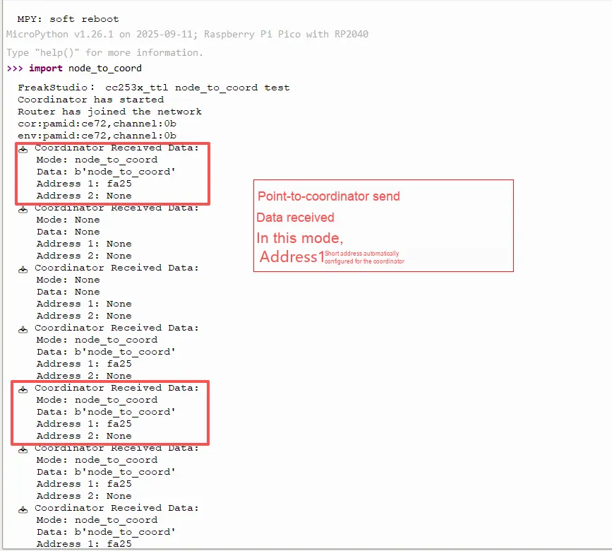
The node sends data, and the master controller successfully parses the information transmission mode.
3.3.3 Coordinator-to-Node Transmission Experiment
Here, we first use the HY2.0-4P connection cable to connect the module to the GraftPort-RP2040 development board's UART0 and UART1 interfaces:
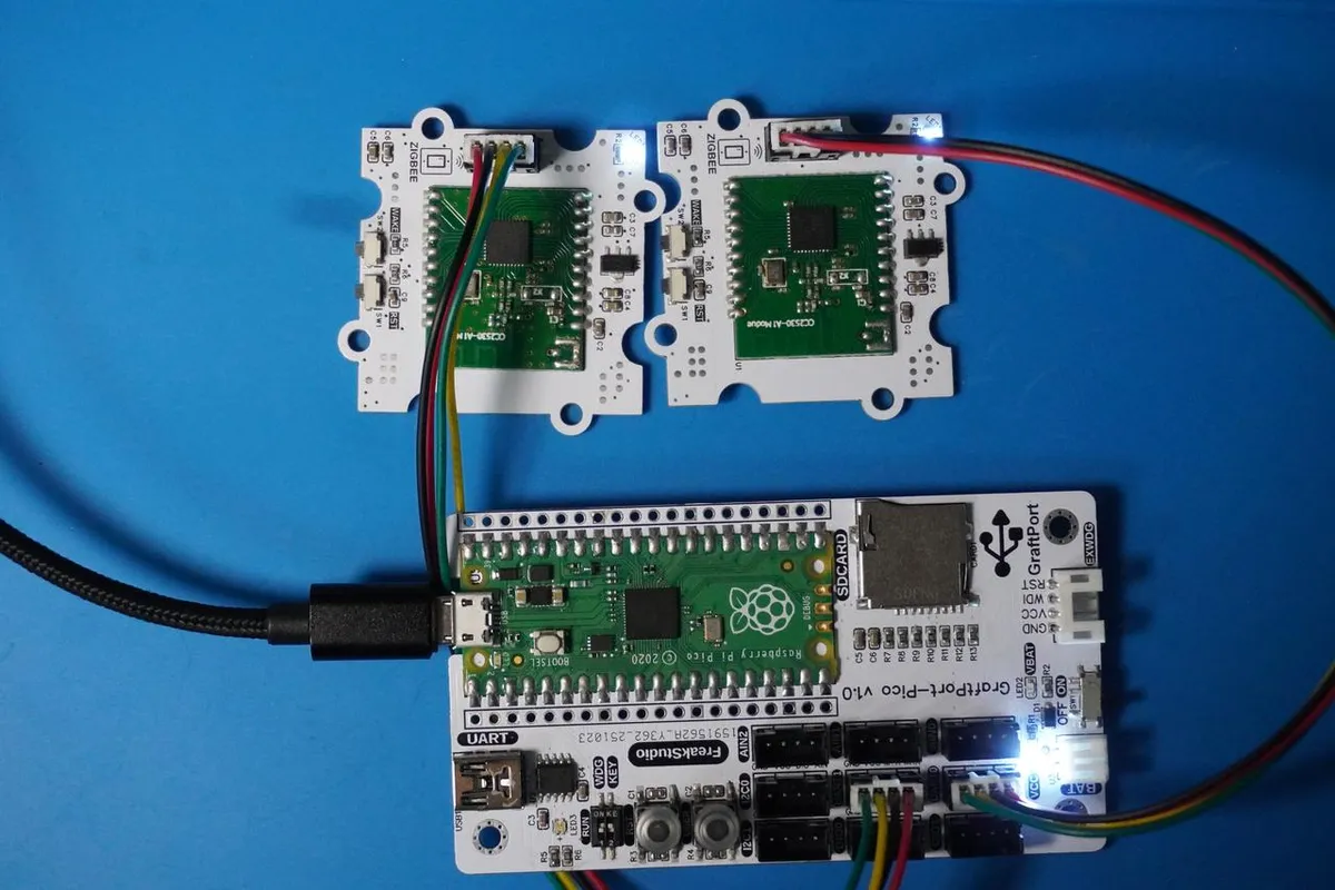
The module connections are shown in the following table:
Router Zigbee:
Development Board Pins | Module Pins | Description |
Pin 16 |
|
|
Pin 17 |
|
|
Coordinator Zigbee:
Development Board Pins | Module Pins | Description |
Pin 8 |
|
|
Pin 9 |
|
|
Import the CC2530 Zigbee driver - MicroPython driver code, then in REPL call coord_to_node. py
# Import file as the main program
import coord_to_node
coord_to_node.py The content is as follows:
# Python env   : MicroPython v1.23.0
# -*- coding: utf-8 -*-
# @Time    : 2025/9/5 10:11 PM
# @Author  : ben0i0d
# @File    : coord_to_node.py
# @Description : cc253x_ttl coord_to_node test file

# ======================================== Import Modules =========================================

# Import hardware-related modules
import time
from machine import UART,Pin
# Import the third-party driver module
from cc253x_ttl import CC253xTTL

# ======================================== Global Variables ============================================

# ======================================== Functions ============================================

# ======================================== Custom Classes =============================================

# ======================================== Initialization configuration ===========================================

# Power-on delay of 3 s
time.sleep(3)
# Print debug information
print("FreakStudio: cc253x_ttl coord_to_node test")

# Declare serial port instance
uart0 = UART(0, baudrate=9600, tx=Pin(16), rx=Pin(17))
uart1 = UART(1, baudrate=9600, tx=Pin(8), rx=Pin(9))

# Coordinator
cor = CC253xTTL(uart0)
# Router
env = CC253xTTL(uart1)
# Set the router and coordinator to the same PANID
while cor.read_status() is None:
    pass
while env.read_status() is None:
    pass

# Get the coordinator PANID and channel
pamid, ch = cor.read_panid_channel()
print(f"cor:pamid:{pamid},channel:{ch}")
while env.set_panid(int(pamid,16)) is False:
    pass
while env.set_channel(int(ch,16)) is False:
    pass

# Output the router PANID and channel
time.sleep(0.5)
pamid, ch = env.read_panid_channel()
print(f"env:pamid:{pamid},channel:{ch}")
# Set the router short address to 0xffff
env.set_custom_short_addr(0xffff)
# ========================================  Main Program  ===========================================

while True:
    # Coordinator sends to the router
    cor.send_coord_to_node(0xffff,"coord_to_node")
    time.sleep(0.5)

    # Coordinator receives and outputs
    mode, data, addr1, addr2 = env.recv_frame()
    print(f"   Coordinator Received Data:")
    print(f"   Mode: {mode}")
    print(f"   Data: {data}")
    # node_to_coord returns the coordinator address addr1
    print(f"   Address 1: {addr1}")
    print(f"   Address 2: {addr2}")
    time.sleep(1)
In this code, we set the short address of the router to 0xffff, and the coordinator will send data to the router node with the address of 0xffff.
REPL Output is as follows:
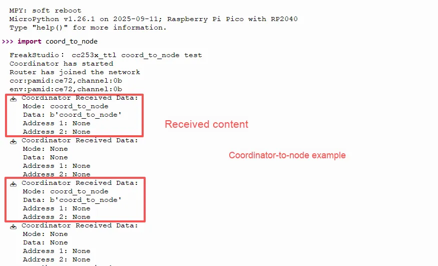
The coordinator sends data, and the main control successfully parses the information transmission mode.
In the communication test between the coordinator and the node, if after modifying the target node address, the coordinator can still only receive messages sent via 0xFFFF (broadcast address), as shown in the following figure:
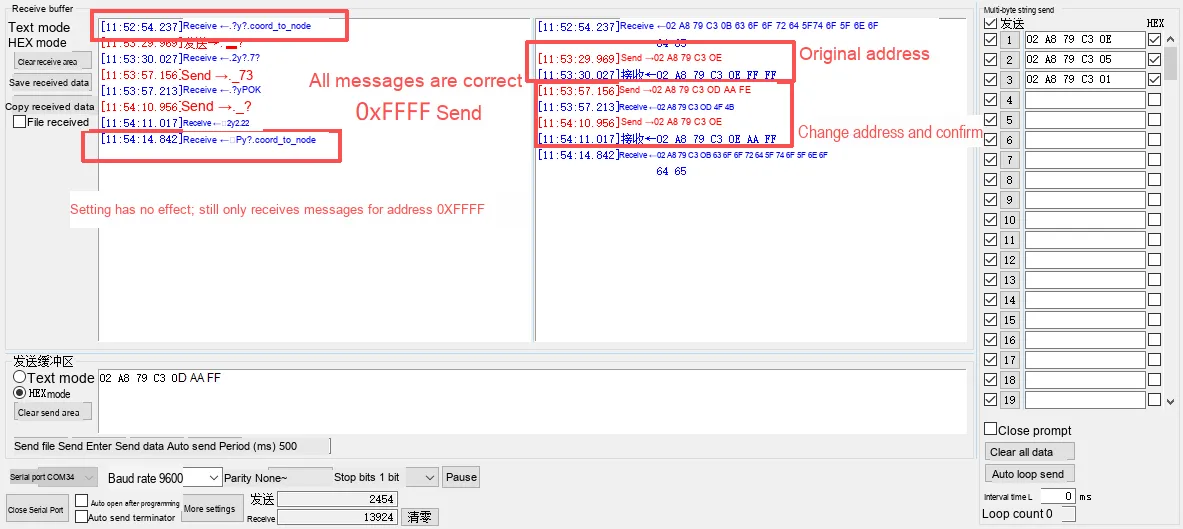
3.3.4 Node-to-Node Transmission Experiment
First, use the HY2.0-4P connection cable to connect the module to the GraftPort-RP2040 development board's UART0 and UART1 interfaces.
This experiment requires 3 ZigBee modules, with the specific configuration as follows: 2 router modules and 1 coordinator module; the coordinator needs to be connected to the TTL serial port module, and the data communication status can be viewed via the XCOM serial port tool.
The module connections are shown in the following table:
Router 1 Zigbee:
Development Board Pins | Module Pins | Description |
Pin 16 |
|
|
Pin 17 |
|
|
Router 2 Zigbee:
Development Board Pins | Module Pins | Description |
Pin 8 |
|
|
Pin 9 |
|
|
Coordinator Zigbee:
| Module Pins | Description |
|
|
|
|
|
|
Import the CC2530 Zigbee driver - MicroPython driver code, we need to obtain the coordinator's PAMID and channel before running the example
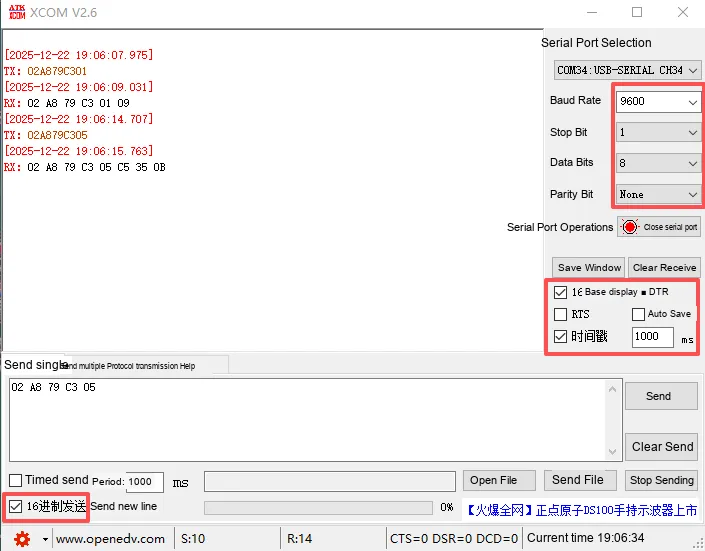
- Baud rate: set to
9600(the rate of serial communication, which needs to be consistent with the hardware end (such as ZigBee module)). - Stop bit:
1bit (a frame format parameter for serial communication, with 1 bit being the common default value). - Data bits:
8bits (the number of valid bits for serial port data, commonly 8 bits). - Parity Bit:
None(no parity, meaning no additional parity bit will be added). - Check items:
Hexadecimal Display: When enabled, the received serial port data will be displayed in hexadecimal format
Open the serial port and send the following hexadecimal commands in sequence
# Get network join status (the reply here should be: 02 A8 79 C3 01 09)
02 A8 79 C3 01
# Get the coordinator PANID and channel (obtain them from the table below)
02 A8 79 C3 05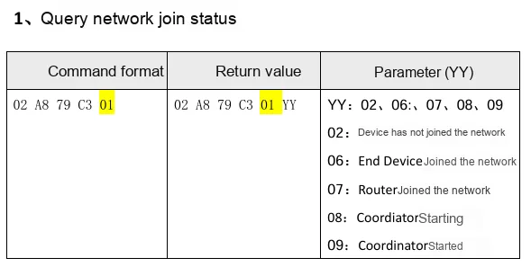
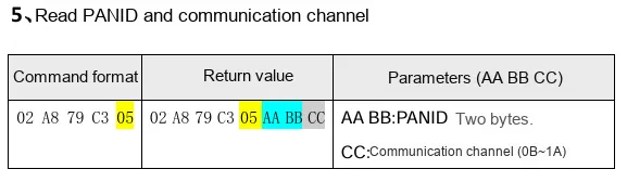
Modify node_to_node.py the global variables in it (after running the code, the communication parameters of the two routers will be consistent with those of the coordinator):
# Coordinator PANID and channel (modify as needed)
pamid =0xc535
ch = 0x0b
coord_to_node.py The content is as follows:
# Python env   : MicroPython v1.23.0
# -*- coding: utf-8 -*-
# @Time    : 2025/9/5 10:11 PM
# @Author  : ben0i0d
# @File    : node_to_node.py
# @Description : cc253x_ttl node_to_node test file

# ======================================== Import Modules =========================================

# Import hardware-related modules
import time
from machine import UART, Pin
# Import the third-party driver module
from cc253x_ttl import CC253xTTL

# ======================================== Global Variables ============================================

# Coordinator PANID and channel (modify as needed)
pamid =0xc535
ch = 0x0b

# ======================================== Functions ============================================

# ======================================== Custom Classes =============================================

# ======================================== Initialization configuration ===========================================

# Power-on delay of 3 s
time.sleep(3)
# Print debug information
print("FreakStudio: cc253x_ttl node_to_node test")

# Declare serial port instance
uart0 = UART(0, baudrate=9600, tx=Pin(16), rx=Pin(17))
uart1 = UART(1, baudrate=9600, tx=Pin(8), rx=Pin(9))

# Router 1
env1 = CC253xTTL(uart0)
# Router
env2 = CC253xTTL(uart1)

# Check network join status and command response
while env1.read_status() is None:
    pass
while env2.read_status() is None:
    pass

# Set the router and coordinator to the same PANID
# Get Router 1 PANID and channel
while env1.set_panid(pamid) is False:
    pass
while env1.set_channel(ch) is False:
    pass

# Get Router 2 PANID and channel
while env2.set_panid(pamid) is False:
    pass
while env2.set_channel(ch) is False:
    pass


# Output the router PANID and channel
time.sleep(0.5)
pamid,ch=env1.read_panid_channel()
print(f"cor1:pamid:{pamid},channel:{ch}")
time.sleep(0.5)
pamid,ch=env2.read_panid_channel()
print(f"cor2:pamid:{pamid},channel:{ch}")

# Router 1 address is 0xaaff
while env1.set_custom_short_addr(0xaaff)[0] is False:
    pass

# Router 2 address is 0xffaa
while env2.set_custom_short_addr(0xffaa)[0] is False:
    pass

# ========================================  Main Program  ===========================================

while True:
    # Coordinator sends to the router
    env2.send_node_to_node(source_addr=0xaaff ,target_addr=0xffaa ,data="node_to_node")
    time.sleep(0.5)
    # Coordinator receives and outputs
    mode, data, addr1, addr2 = env1.recv_frame()
    print(f"   Coordinator Received Data:")
    print(f"   Mode: {mode}")
    print(f"   Data: {data}")
    # node_to_coord returns the coordinator address addr1
    print(f"   Address 1: {addr1}")
    print(f"   Address 2: {addr2}")
    time.sleep(1)
Burn the code, then REPL call node_to_node.py
# Import file as the main program
import coord_to_node
REPL outputs the following:
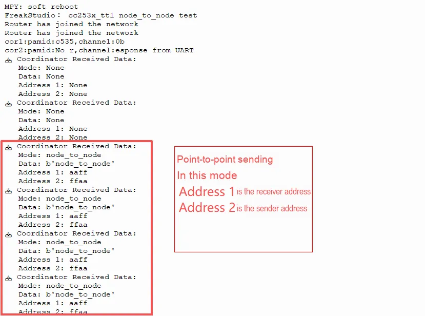
After forming a network, they successfully communicate with each other based on addresses.
IV. Drivers
cc2530_driver.zip 16 KB
5. BOM & Recommended Alternative Parts
None.
VI. Revision History
Document Version | Date of Revision | Modifier | Modified Content |
v1.0 | 2025-10-24 | Ling Gaoxing | Initialize the document |
v1.1 | 2025-12-29 | Li Zisheng | Added application experiments and production files |
v1.2 | 2025-12-31 | Xin Ruili | Create an open version of the document based on the internal document version v1.1. |
v1.3 | 2026-03-29 | Xin Ruili | Modified the application experiment section. |
VII. Relevant Materials
7.1 Chip Datasheet
RL-CC2530-A1.doc 784 KB
ZIGBEE Serial Transparent Transmission Module User Manual V1.3.docx 1.0 MB
7.2 Unique Icons for PCB Silkscreen