Contents
- I. Module Introduction
- II. Introduction to Major Chips
- 2.1 Chip Overview
- 2.2 Pin Definition
- 2.3 Functional Block Diagram
- 2.4 Performance Parameters
- 2.5 Reference Circuit
- 2.6 Chip Configuration
- 2.7 Communication Interfaces and Related Protocols
- 2.8 PCB Routing Precautions
- III. Circuit Engineering
- 3.1 Circuit Source Engineering
- 3.2 Module Usage Instructions
- 3.3 Application Experiment
- IV. Drivers
- 5. BOM & Recommended Alternative Parts
- VI. Revision History
- VII. Relevant Materials
- 7.1 Chip Datasheet
- 7.2 Unique Icons for PCB Silkscreen
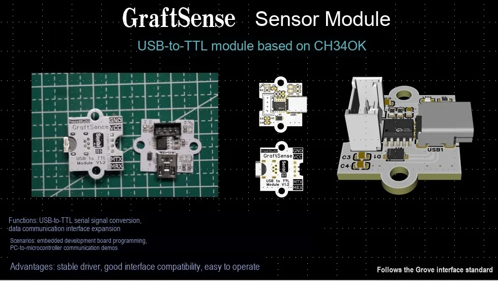
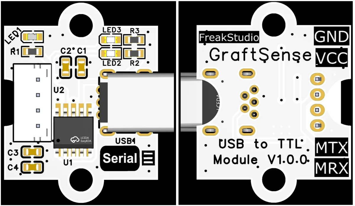
I. Module Introduction
CH340K-based USB-to-TTL Module Designed based on the CH340K chip, this module integrates the USB-to-TTL level serial port function, is equipped with a sensor interface, indicator lights and filter circuit, supports external USB power supply, and can realize serial communication between USB and devices such as MCUs. It also reduces interference through designs such as decoupling capacitors, making it suitable for serial communication scenarios such as embedded development.
II. Introduction to Major Chips
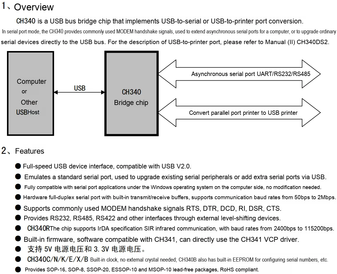
Adopts CH340K USB-to-TTL chip.
2.1 Chip Overview
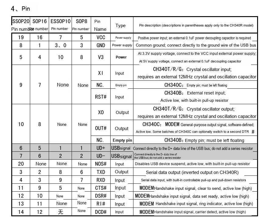
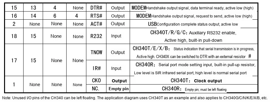
2.2 Pin Definition
2.3 Functional Block Diagram
This chip does not have a functional block diagram, but its internal structure can be divided into the following parts:
- USB Interface Unit: Serving as the communication bridge between the CH340K and the computer, it supports the USB 2.0 Full-Speed protocol (backward compatible with USB 1.1), can recognize USB data commands from the computer side, transmit the USB data sent by the computer to the inside of the chip, and meanwhile convert the feedback data from the TTL serial port side into USB format for postback to the computer, so as to realize the two-way data interaction between the computer and the chip.
- TTL Serial Port Unit: Responsible for serial communication between the chip and external TTL level devices (such as 51 microcontrollers, STM32, sensor modules, etc.), it supports adjustable baud rates from 300bps to 2Mbps, and is compatible with 8 data bits, 1/2 stop bits, and no parity/odd parity/even parity bits. It can receive TTL level data from external devices and transmit it to the chip, as well as convert the USB data processed by the chip into TTL level and send it to external devices.
- Control Logic Unit: the "core scheduling hub" of the chip, which is responsible for parsing computer instructions transmitted from the USB interface unit, configuring communication parameters of the TTL serial port unit (such as baud rate and parity mode), coordinating the read and write timing of the data buffer unit, and managing the working status of the status indication unit, so as to ensure the orderly and logical collaboration of all components and realize the data format conversion and bidirectional transmission between USB and TTL serial port.
- Data buffer unit: used to temporarily store interactive data between the USB interface and the TTL serial port, so as to avoid data loss caused by the mismatch of communication rates between the two ends (for example, the USB rate is much higher than the serial port rate). When the data transmission rate of one end is slow, the data can be temporarily stored in the buffer unit first, and then transmitted gradually after the other end is ready, so as to improve the stability of data transmission.
- Power Management Unit: It supports 5V USB power supply or external 5V/3.3V DC power supply, with built-in voltage regulator circuit and overcurrent protection mechanism. It can stably convert the input voltage into the operating voltage required inside the chip (e. g., 3.3V), and meanwhile provide optional 3.3V/5V auxiliary power supply for external TTL devices, so as to ensure the stable operation of the chip and external circuits in different power supply scenarios and prevent voltage fluctuations from interfering with communication.
- Status Indication Unit: Typically connected to external LED indicators (such as TX transmit indicator, RX receive indicator, and power indicator), which are triggered by the control logic unit according to the operating status: a steadily lit power indicator indicates normal power supply to the chip; a flashing TX indicator indicates that the chip is transmitting data to an external TTL device; a flashing RX indicator indicates that the chip is receiving data from an external TTL device. It intuitively feeds back the chip's power supply and data transmission status through the lighting status, facilitating development and debugging.
2.4 Performance Parameters
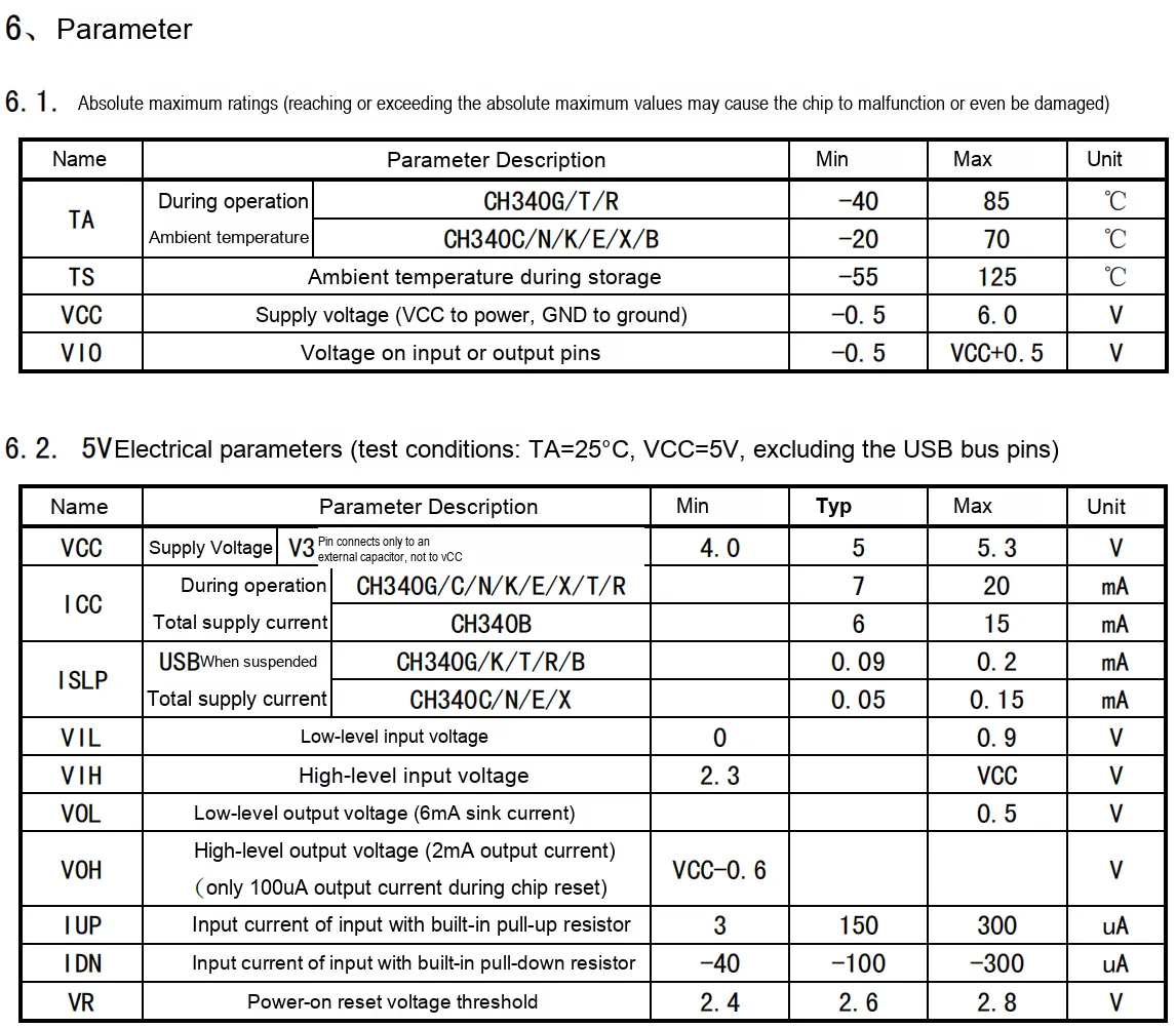
- Absolute Maximum Ratings: Operating ambient temperature (e. g., -40℃ to 85℃ for CH340G/T/R), storage ambient temperature (-55℃ to 125℃), power supply voltage VCC (-0.5V to 6.0V), I/O pin voltage (-0.5V to VCC+ 0.5V) — these are the limiting conditions for safe chip operation; exceeding them may cause malfunction or damage.
- 5V Electrical Parameters:
- Supply Voltage
VCC(typical value 5V, range 4.0V~5.3V), which provides a range reference for the 5V power supply of the chip; - Total operating current
ICC(e. g., typical 7mA for theCH340Gseries), which reflects the power consumption during 5V operation; - High and low level input voltage (
VILmax. 0.9V,VIHmin. 2.3V), which defines the identification thresholds for input logic "0" and "1"; - High and low level output voltage (
VOLmax. 0.5 V,VOHmin. VCC – 0.6 V), which specifies the driving capability of the output logic level; - Input current with internal pull-up/down resistors (
IUPmax. 300μA,IDNmin. -300μA), which affects the current characteristics when external pull-up/down resistors are connected to the pin; - Power-on reset voltage threshold of the power supply
VR(2.4V~2.8V), which is the voltage range that triggers reset when the power supply starts up.
- Supply Voltage
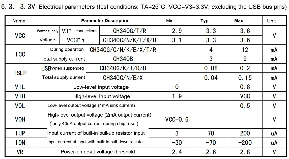
- 3.3V Electrical Parameters:
- Power Supply Voltage
VCC(Typical value: 3.3V; for CH340G/T/R, the operating range is 2.9V to 3.6V), suitable for 3.3V power supply scenarios; - Total operating current
ICC(e. g., typical 4mA for the CH340G series), which reflects the power consumption when operating at 3.3V; - High and low level input voltage (
VILmax. 0.8V,VIHmin. 1.9V), which defines the identification threshold of input logic level at 3.3V; - High and low level output voltage (
VOLmax. 0.5V,VOHmin. VCC-0.6V), which specifies the driving capability of the output logic level when powered by 3.3V; - The input current of the pull-up/pull-down resistors built into the chip (
IUPmax. 200μA,IDNmin. -200μA) will affect the current characteristics of the external pull-up/pull-down resistors connected to the pins at 3.3V; - Power-on reset voltage threshold
VR(2.4V~2.8V), which refers to the voltage range for power supply start-up reset when powered by 3.3V.
- Power Supply Voltage
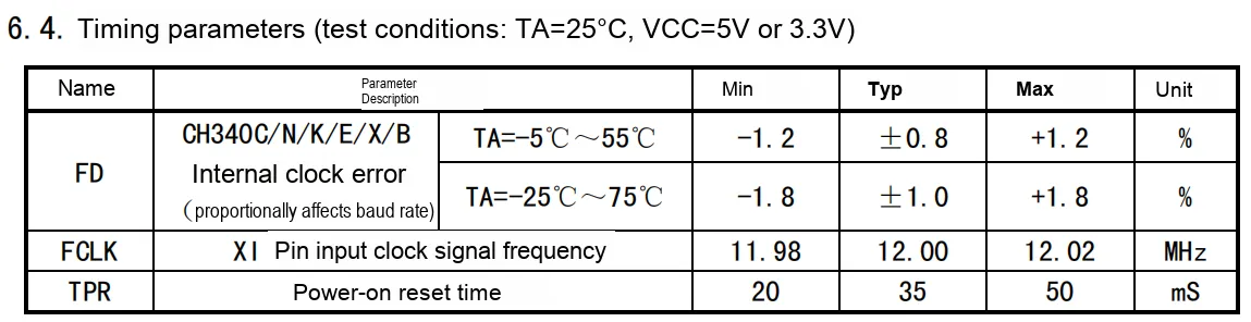
- Timing Parameters:
- internal clock error
FD(the error varies across different temperature ranges; for example, whenTA= -5°C to 55°C, the typical value is ±0.8%), which determines the accuracy of the serial communication baud rate; - Input clock frequency
FCLK(typically 12.00MHz, ranging from 11.98MHz to 12.02MHz), which serves as the clock reference for the chip operation; - Power-on reset time
TPR(typical value: 35mS, range: 20mS~50mS), which refers to the reset duration from power supply startup to the chip being able to operate normally.
- internal clock error
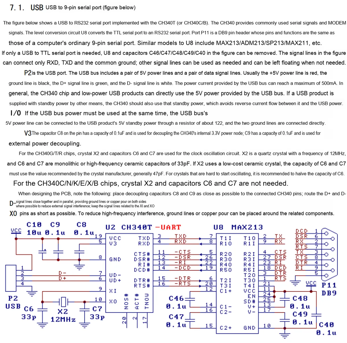
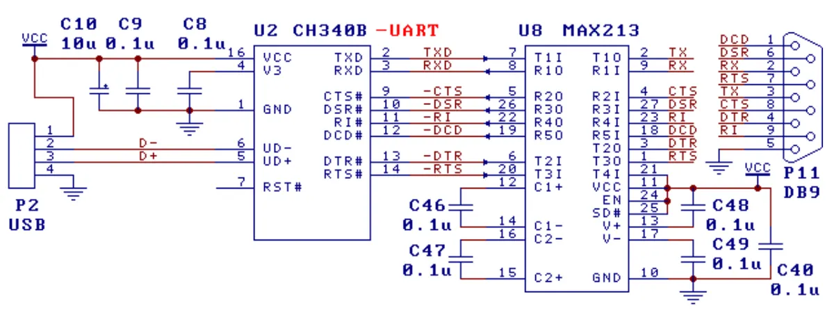
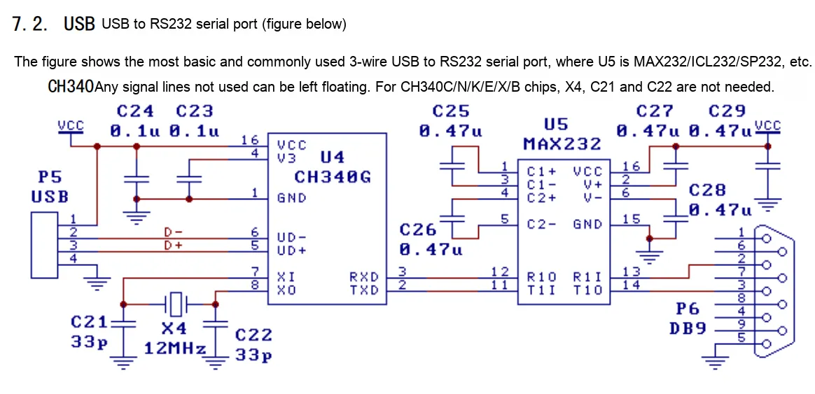
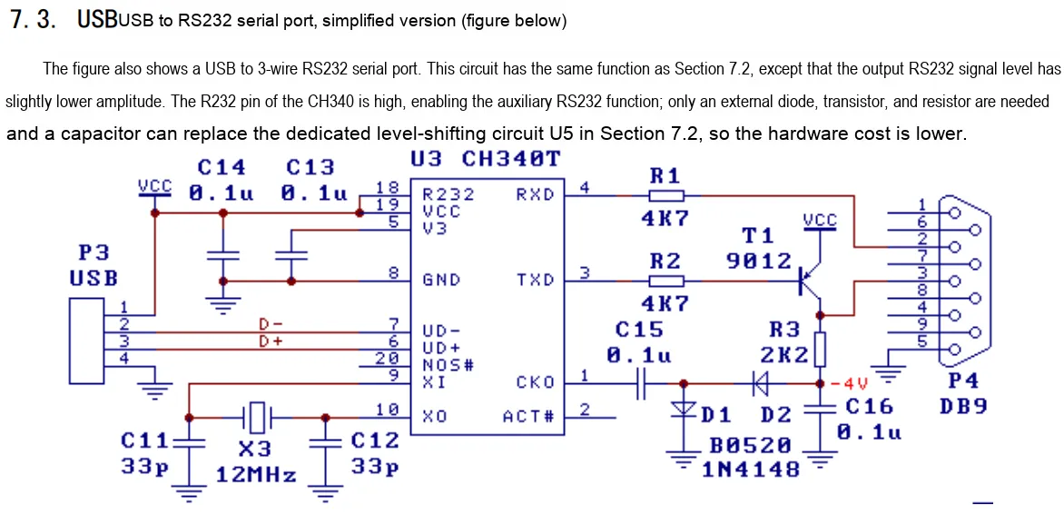
2.5 Reference Circuit

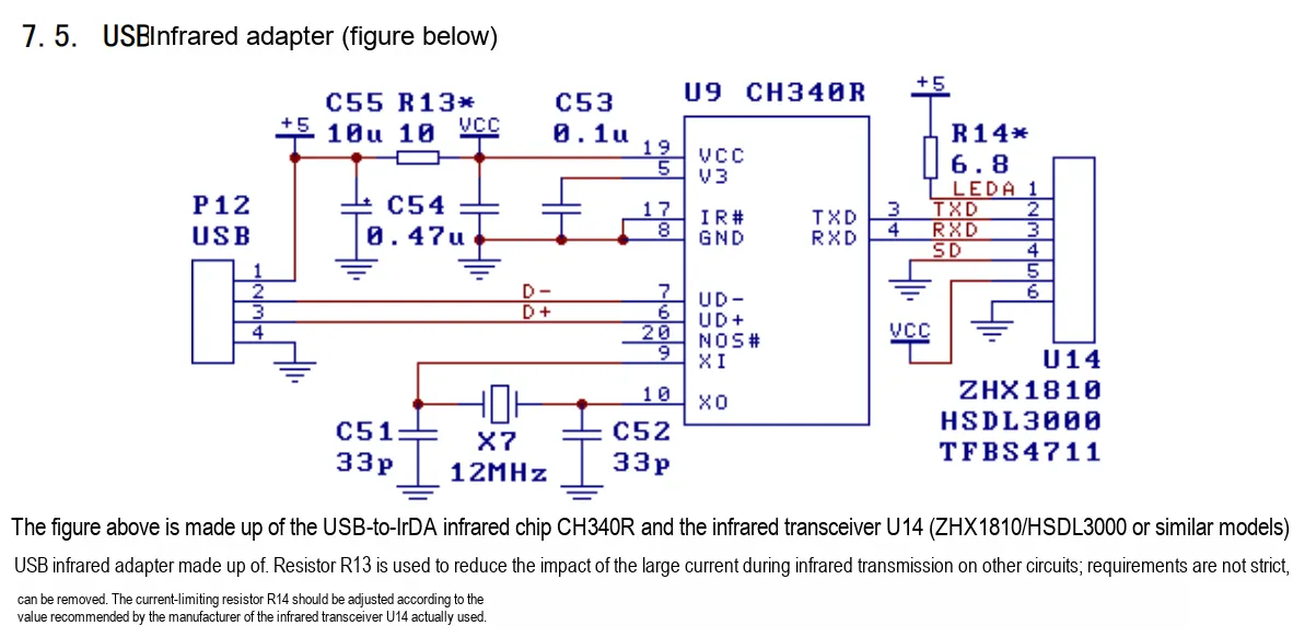
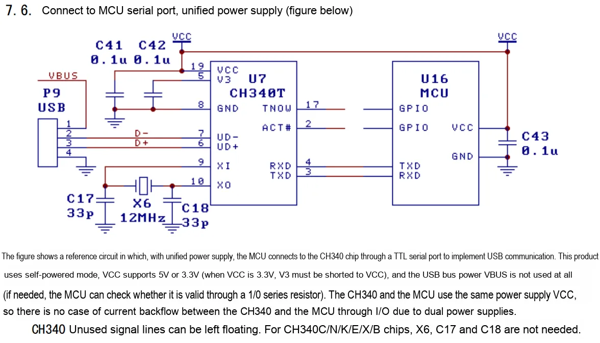
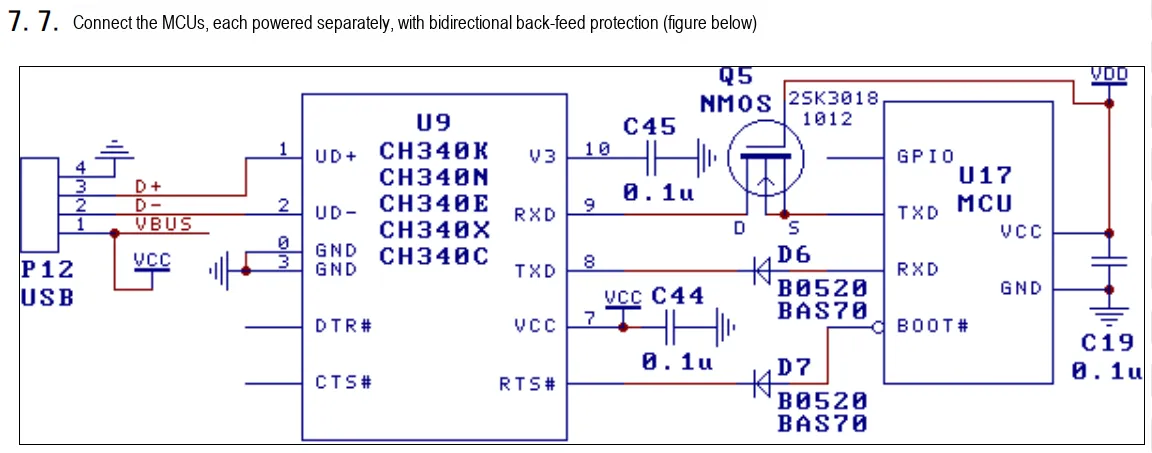
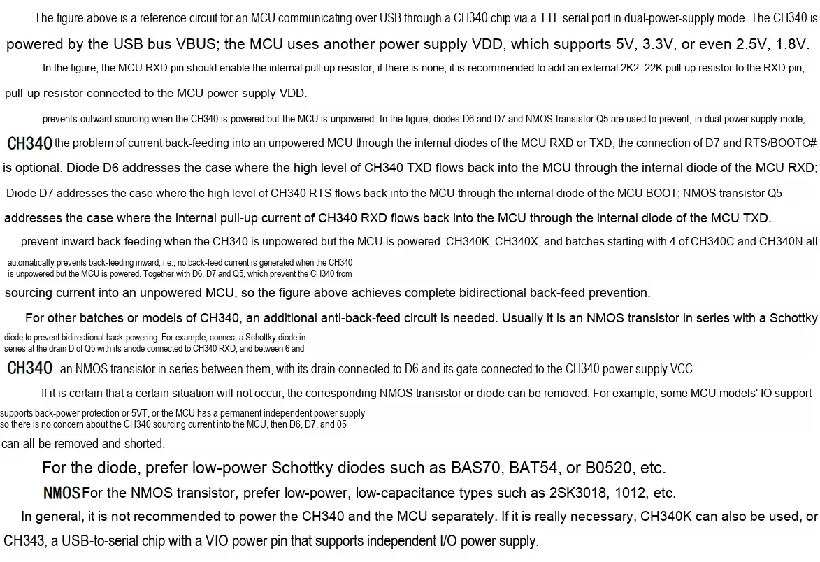
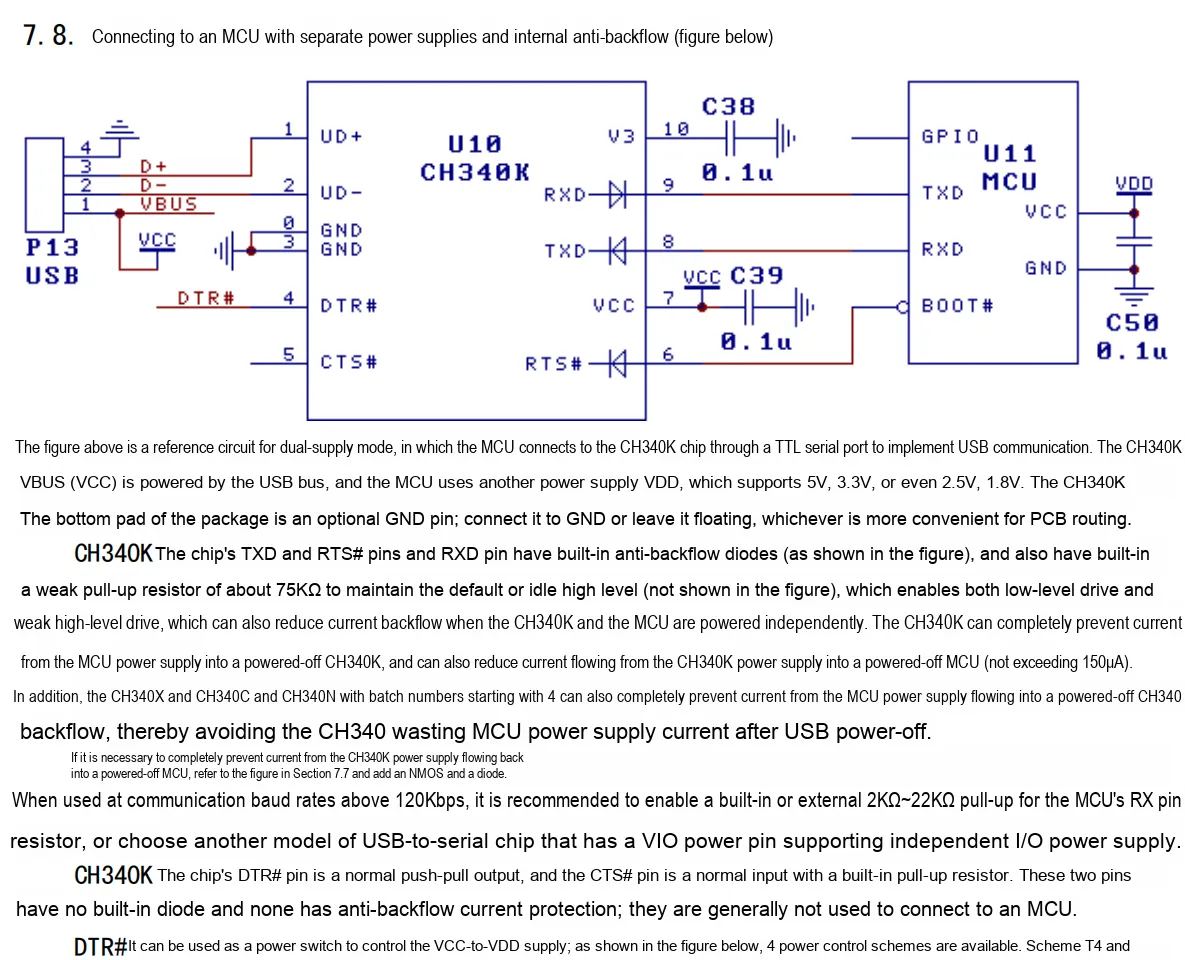
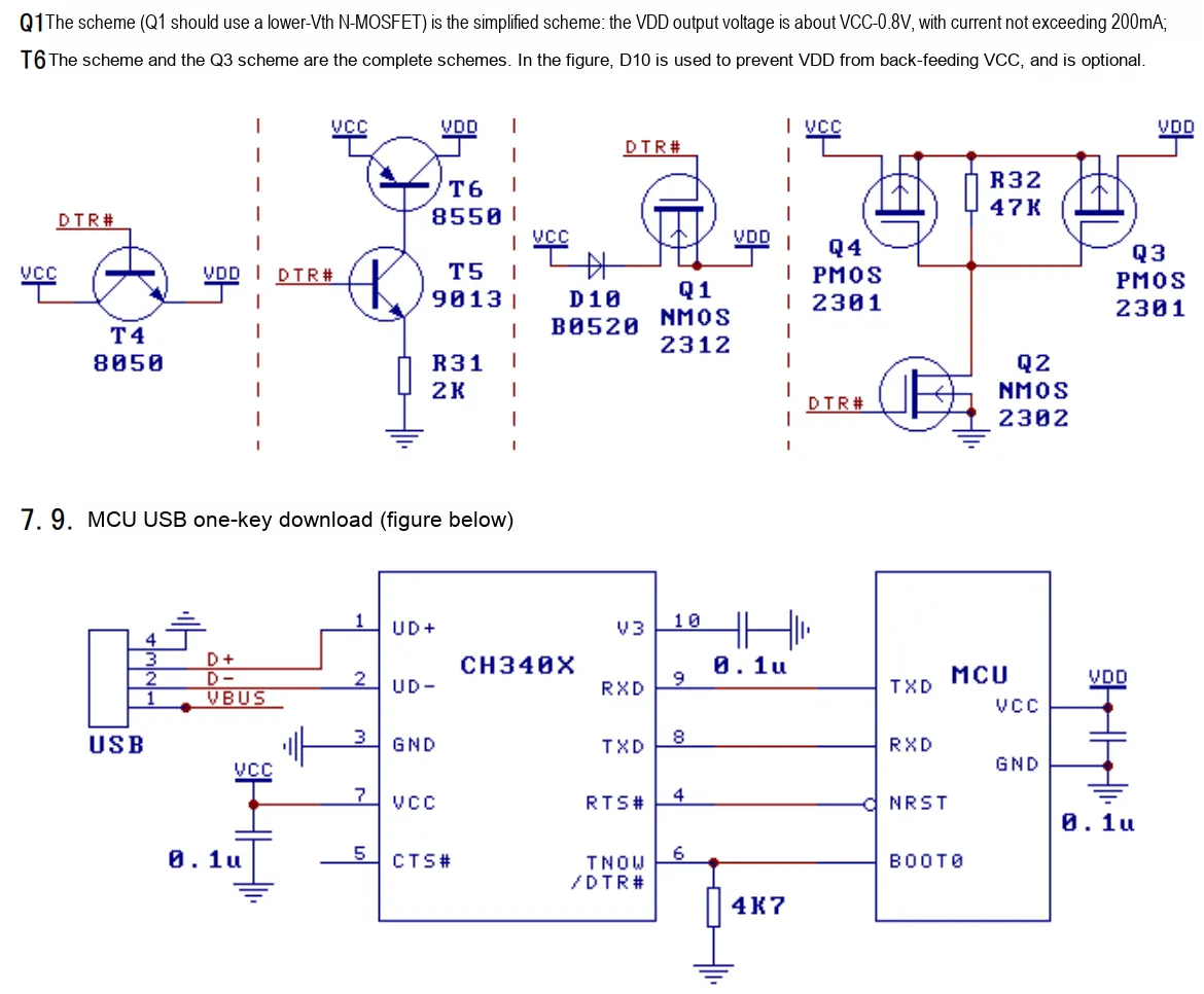
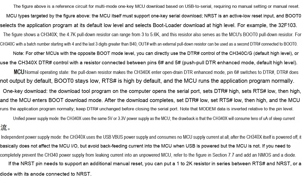
2.6 Chip Configuration
None.
2.7 Communication Interfaces and Related Protocols
None.
2.8 PCB Routing Precautions
None.
III. Circuit Engineering
3.1 Circuit Source Engineering
To obtain the source project of the circuit, please follow the official account [Freak Embedded]
3.2 Module Usage Instructions
The schematic diagram of this module is shown below:
SCH_USB to TTL Module Based on CH340K_v1.0_2025-09-25.pdf 2.4 MB
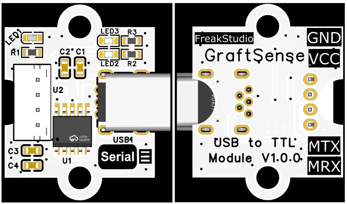
The MRX (corresponding to the UART RXD pin of the MCU) of this module is actually connected to the CH340K 's TXD pin, and the MTX (corresponding to the UART TX pin of the MCU) is actually connected to the CH340K ' s RXD pin; this is because UART serial communication follows the "cross-transmit-receive" rule — the transmit terminal (TX) of both communication parties needs to be connected to the receive terminal (RX) of the other party, and this design ensures correct bidirectional transmission of UART serial data between the MCU and the CH340K.
Of particular note is that when using this module, MRX is directly connected to the RXD pin of the MCU's serial port, and MTX is directly connected to the TXD pin of the MCU's serial port; be sure not to cross-connect them.
3.3 Application Experiment
Here, we use the GraftPort-RP2040 development board for testing, and the USB-to-TTL module based on CH340K uses the UART interface on it to communicate with the main controller.
Here, we first use the HY2.0-4P cable to connect the module to the GraftPort-RP2040 development board's UART1 interface:
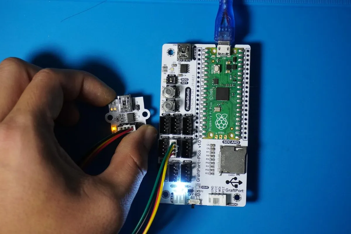
Meanwhile, use the Mini-USB cable to connect the computer to the USB-to-TTL module based on CH340K via the USB port:
The module connections are shown in the following table:
Development Board Pins | Module Pins | Description |
Pin 8 |
|
|
Pin 9 |
|
|
Import Serial Port Loopback Test Code - MicroPython Driver Code
Then copy the following test main.py code into our project:
# Python env   : MicroPython v1.23.0
# -*- coding: utf-8 -*-
# @Time    : 2025/09/04 10:00
# @Author  : 侯钧瀚
# @File    : main.py
# @Description : Serial loopback test code

# ======================================== Import Modules =========================================

from machine import UART, Pin
import time

# ======================================== Global Variables ============================================

# Test message counter
count = 1

# ======================================== Functions ============================================

# ======================================== Custom Classes ============================================

# ======================================== Initialization ==========================================

# Power-on delay of 3 s
time.sleep(3)
print("FreakStudio: UART loopback test started. Sending data every 2 seconds...")

# Initialize UART1: TX=Pin8, RX=Pin9, baud rate 9600
uart = UART(0, baudrate=9600, tx=Pin(8), rx=Pin(9))

# ========================================  Main Program  ===========================================

try:
    while True:
        # Build test message with counter
        test_msg = f"Test message {count}: Hello, UART loopback!"
        print(f"\nSent: {test_msg}")

        # Send message
        uart.write(test_msg.encode('utf-8'))

        # Wait a short time to receive data
        time.sleep(0.1)

        # Read and print received data
        if uart.any():
            received = uart.read(uart.any()).decode('utf-8')
            print(f"Received: {received}")
        else:
            print("Received: No data (check connections)")

        # Increment counter and wait 2 seconds before the next send
        count += 1
        time.sleep(2)

except KeyboardInterrupt:
    # Catch keyboard interrupt to end the test
    print("\nTest stopped by user")
Burn the code and open the terminal
After the code runs, it will send serial data through the module, and the content sent from the computer side will be printed to the terminal:
The code for the serial port loopback function has been successfully implemented, and the function verification is normal.
IV. Drivers
usb_ttl_code.zip 1 KB
This module requires the installation of the CH340 driver on the computer. After the driver is installed, the USB-to-TTL module will appear in the operating system as a virtual serial port device. The CH340 driver can be downloaded below:
CH341SER.EXE 643 KB
5. BOM & Recommended Alternative Parts
None.
VI. Revision History
Document Version | Date of Revision | Modifier | Modified Content |
v1.0 | 2025-08-31 | Ling Gaoxing | Initialize the document |
v1.1 | 2025-09-25 | Li Zisheng | Added 2.8 PCB routing precautions Revised Section 3, Instructions for Circuit Source Project and Module Usage, and added a secondary heading: 3.1 Circuit Source Engineering, 3.2 Module Usage Instructions, 3.3 Application Experiments The driver has not been rechecked yet, 3.3 Application Experiment Not yet specified. |
v1.2 | 2025-12-29 | Li Zisheng | Added application experiments and production files |
v1.3 | 2025-12-31 | Xin Ruili | Create an open version of the document based on the internal document version v1.2. |
VII. Relevant Materials
7.1 Chip Datasheet
USB to TTL Module.pdf 228 KB
7.2 Unique Icons for PCB Silkscreen