Contents
- I. Module Introduction
- II. Introduction to Major Chips
- 2.1 Chip Overview
- 2.2 Pin Definition
- 2.3 Functional Block Diagram
- 2.4 Performance Parameters
- 2.5 Reference Circuit
- 2.6 Chip Configuration
- 2.7 Communication Interfaces and Related Protocols
- 2.8 PCB Routing Precautions
- III. Circuit Engineering
- 3.1 Circuit Source Engineering
- 3.2 Module Usage Instructions
- 3.3 Application Experiment
- IV. Drivers
- 5. BOM & Recommended Alternative Parts
- VI. Revision History
- VII. Relevant Materials
- 7.1 Chip Datasheet
- 7.2 PCB Silkscreen Specific Icons
I. Module Introduction
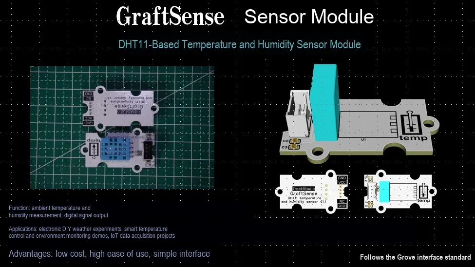
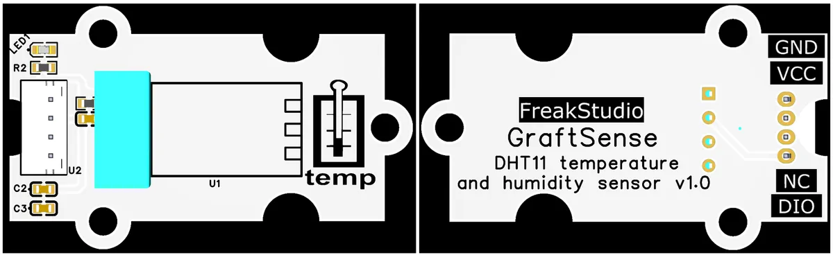
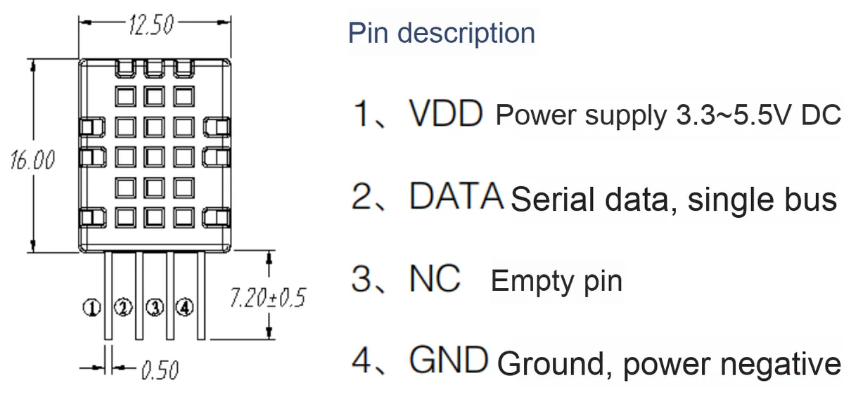
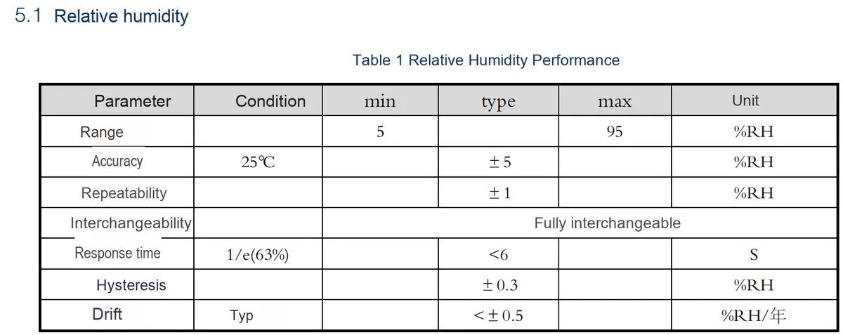
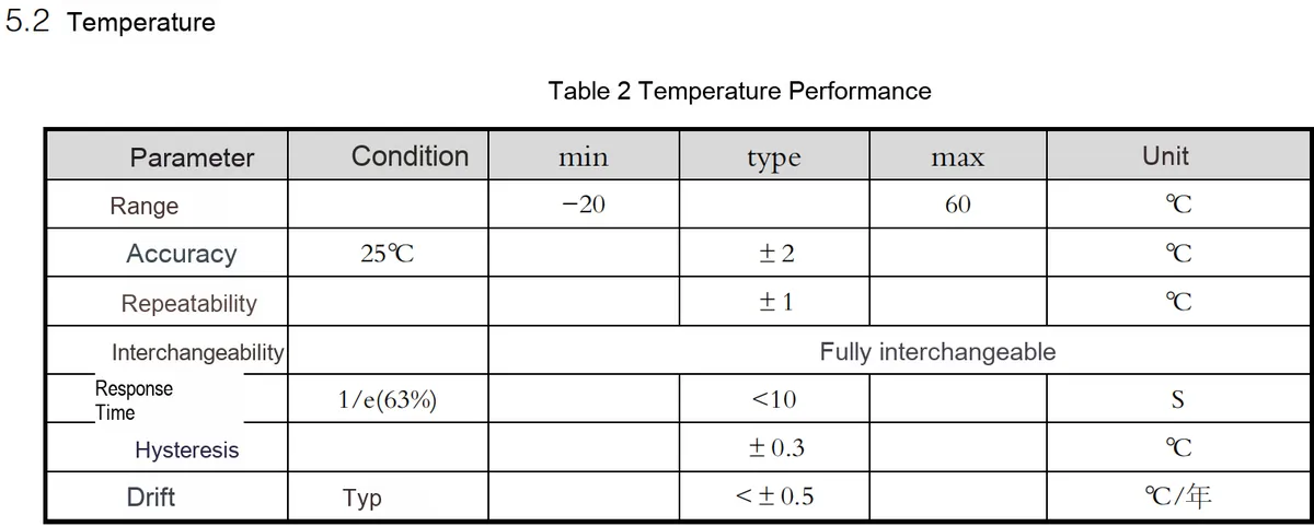
DHT11-based Temperature and Humidity Sensor Module takes DHT11 digital temperature and humidity sensor as the core. In terms of hardware, it builds a stable measurement circuit through a 4.7kΩ pull-up resistor and a 100nF filter capacitor, adopts + 5V power supply, and realizes one-wire digital communication via the DIO pin. Functionally, it can collect ambient temperature and humidity in real time (temperature: 0 - 50℃ ±2℃, humidity: 20 - 90% RH ±5% RH), and is applicable to temperature and humidity Data Acquisition in scenarios such as smart homes and environmental monitoring.
II. Introduction to Major Chips
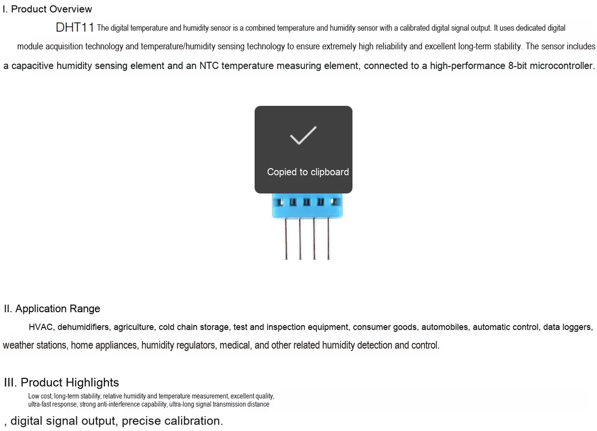
The core of the module is DHT11 digital temperature and humidity sensor (Guangzhou Aosong Electronics, Version V1.3).
- Key Features: With built-in temperature and humidity acquisition and A/D conversion, it outputs a single-bus digital signal; factory-calibrated for excellent long-term stability.
- Internal Structure: Consists of a capacitive humidity sensor, an NTC temperature sensor, an 8-bit microcontroller, and a calibration storage unit.
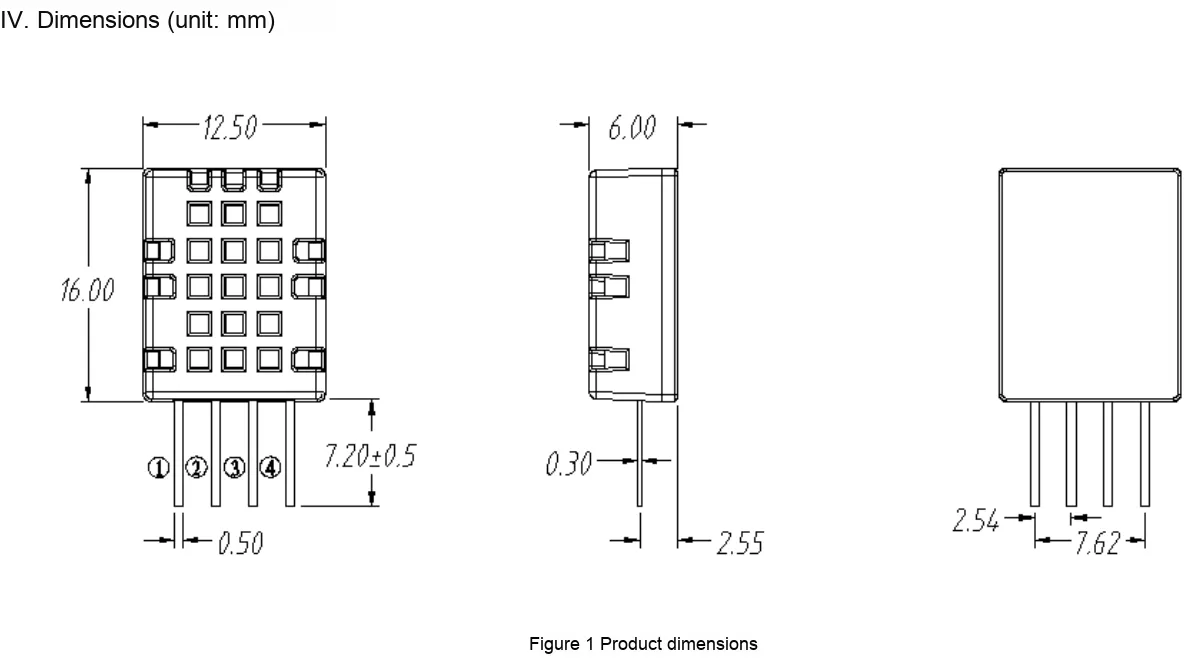
- Package form: Commonly available in 4-pin plastic encapsulated configuration (through-hole or surface-mount).
2.1 Chip Overview
2.2 Pin Definition
2.3 Functional Block Diagram
None.
2.4 Performance Parameters
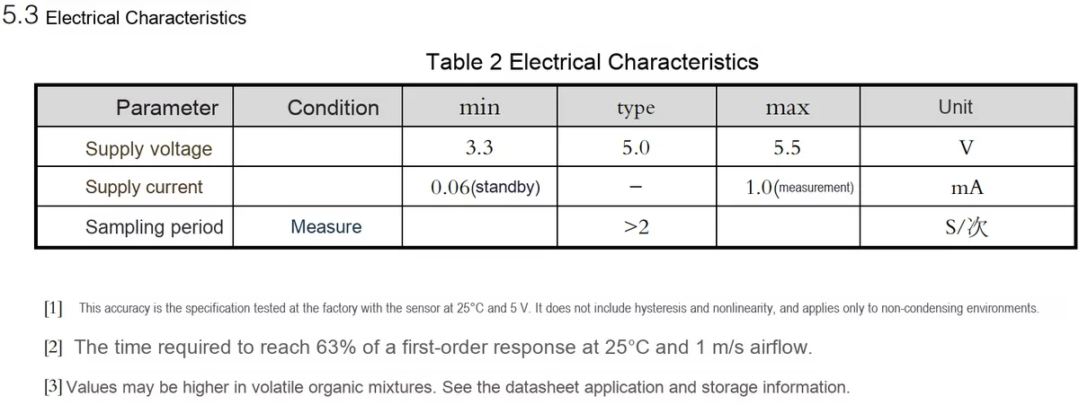
2.5 Reference Circuit
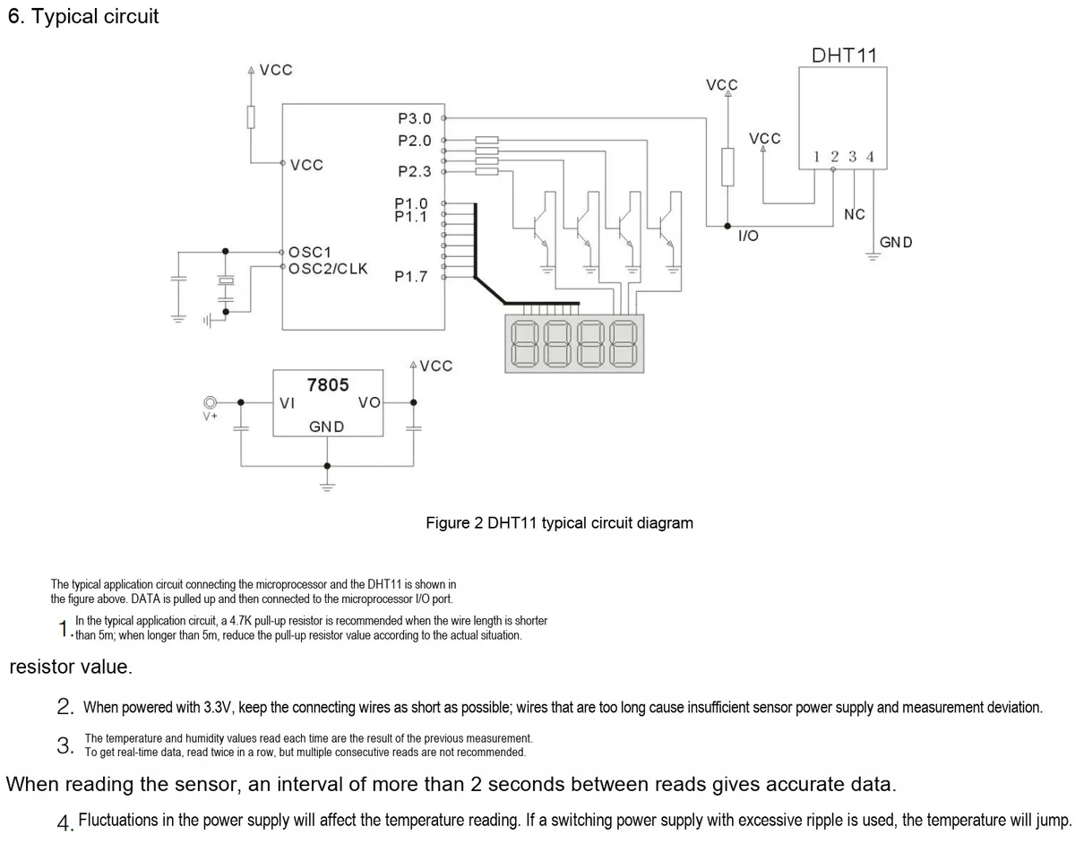
2.6 Chip Configuration
None.
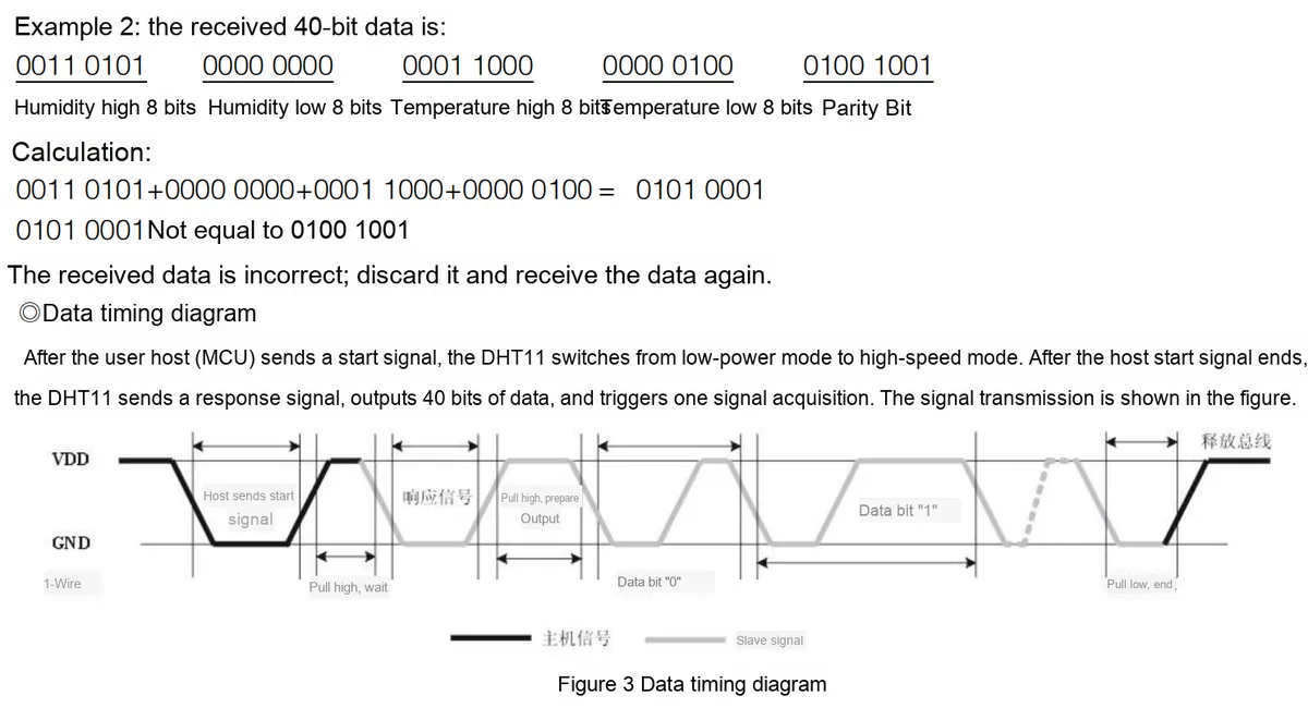
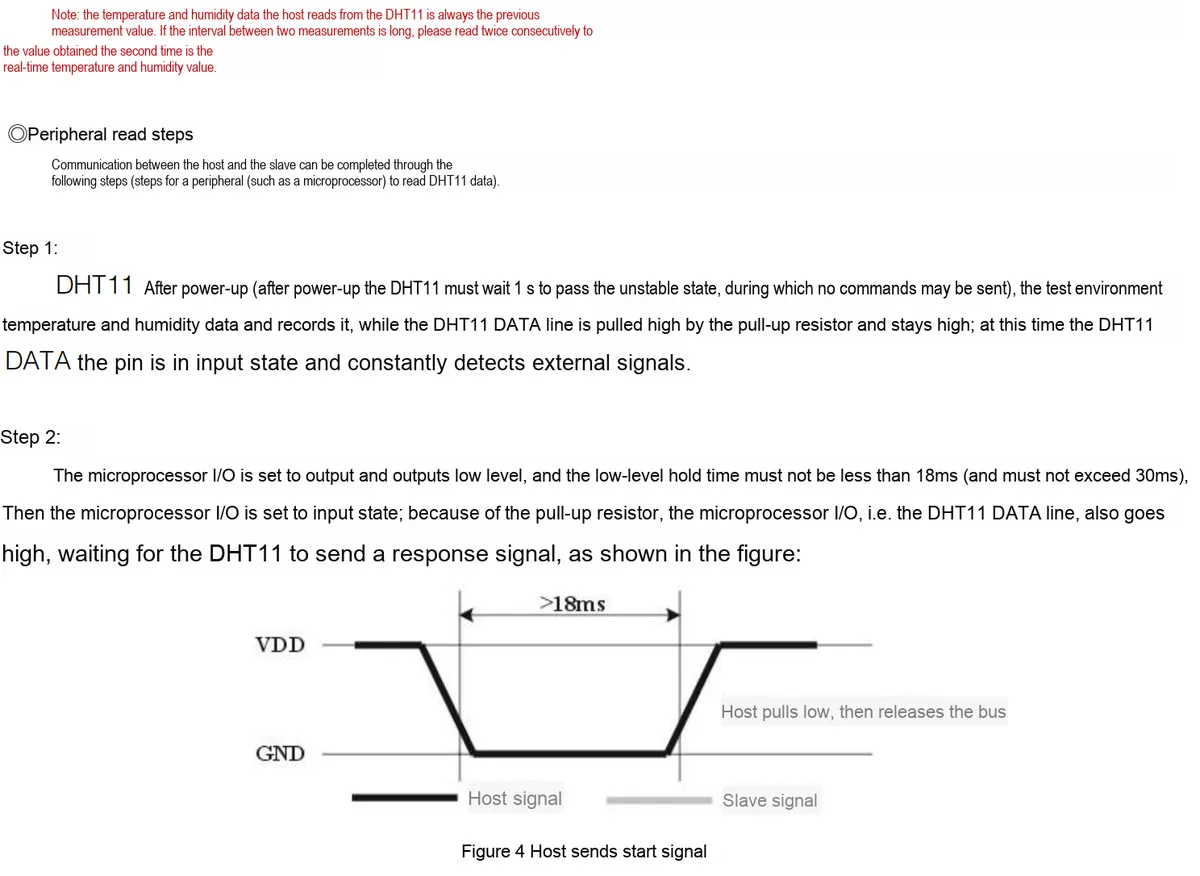
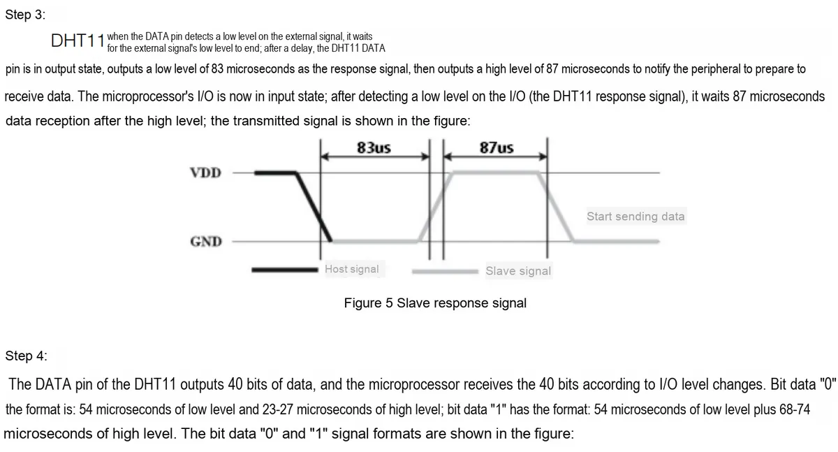
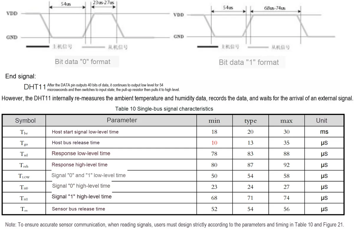
2.7 Communication Interfaces and Related Protocols
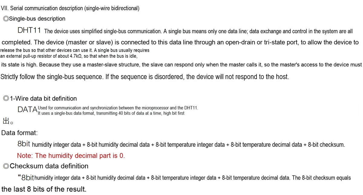
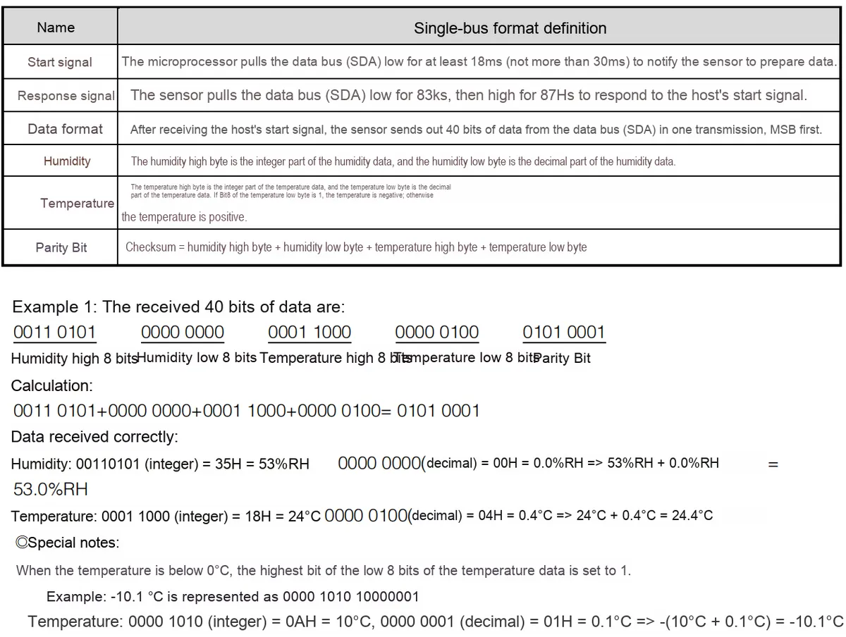
2.8 PCB Routing Precautions
None.
III. Circuit Engineering
3.1 Circuit Source Engineering
To obtain the source project of the circuit, please follow the official account [Freak Embedded]
3.2 Module Usage Instructions
The schematic diagram of this module is shown below:
SCH_Temperature and Humidity Sensor Module Based on DHT11_v1.1_2025-10-10.pdf 1.7 MB
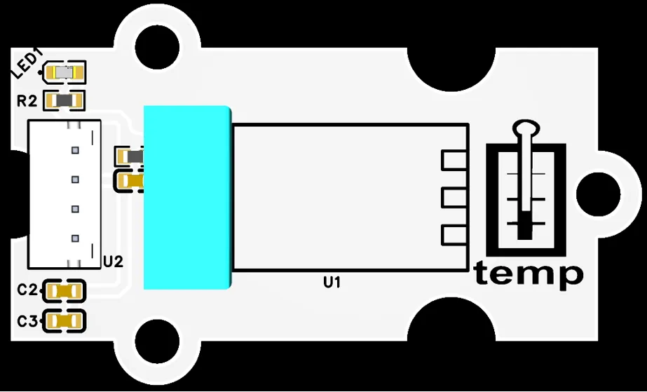
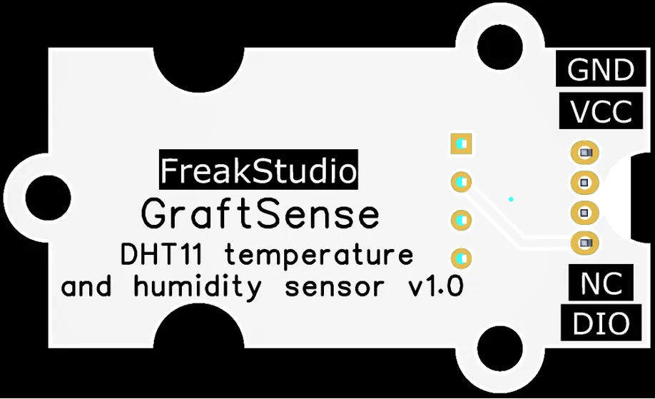
This module adopts single-bus signal output DIO: When the external master device initiates communication, the module establishes a single-bus connection with the master through the DIO pin, and completes the interaction of temperature and humidity data via the single-bus protocol of the DHT11 sensor. Specifically, the master can trigger data transmission by pulling down the DIO pin, and the DHT11 will feed back temperature and humidity information in the format of "humidity integer, humidity decimal, temperature integer, temperature decimal, checksum" with a 40-bit digital signal;Meanwhile, the 4.7kΩ pull-up resistor in the circuit ensures that DIO pin remains at a high level when idle, and the 100nF filter capacitor suppresses signal interference to make one-wire communication more stable, thus realizing accurate and convenient collection of ambient temperature and humidity.
3.3 Application Experiment
Here, we use the GraftPort-RP2040 development board for testing, and connect the DHT11-based temperature and humidity sensor module to communicate with the main controller via the DIO interface.
Here, we first use the HY2.0-4P connection cable to connect the module to the GraftPort-RP2040 development board's DIO0 interface:
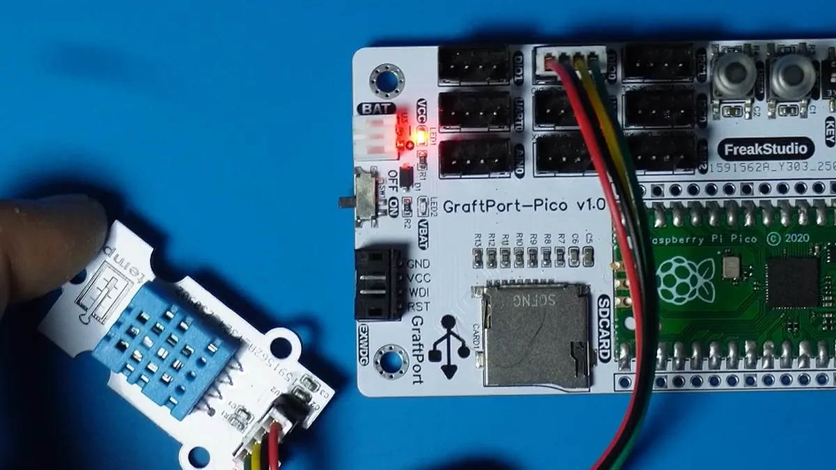
The module connections are shown in the following table:
Development Board Pins | Module Pins | Description |
Pin 6 |
| 1-Wire communication pin |
Pin 7 |
| - |
Here, we need to search for the relevant driver packages on uPyPI: https://upypi.net/zh/
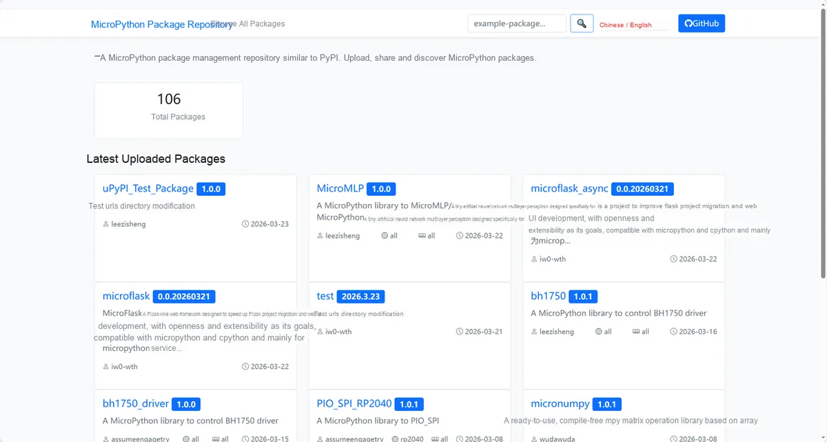
Enter dht11_driver to search, and the following will be displayed:

Click to copy the local installation command:
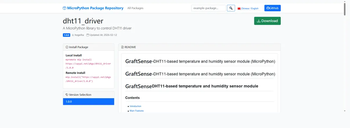
Here, we can use the mip tool to import module driver library code. Below are the usage commands for the mpremote tool:
mpremote mip install github:FreakStudioCN/GraftSense-Drivers-MicroPython/sensors/dht11_driverAfter importing the DHT11 driver - MicroPython driver code, copy the following main.py code into our project:
# Python env   : MicroPython v1.23.0
# -*- coding: utf-8 -*-
# @Time    : 2024/7/22 2:57 PM
# @Author  : Li Qingshui
# @File    : main.py
# @Description : DHT11 temperature and humidity sensor class experiment, using single-bus communication for data exchange

# ======================================== Import Modules ========================================

# Import hardware-related modules
from machine import Pin
# Import time-related modules
import time
from dht11 import DHT11
# ======================================== Global Variables ============================================

# Humidity data
humidity = 0.0
# Temperature data
temperature = 0.0

# ======================================== Functions ============================================

# ======================================== Custom Classes ============================================

# ======================================== Initialization ==========================================

# Delay to wait for the device to initialize
time.sleep(3)
# Print debug information
print('FreakStudio : Using OneWire to read DHT11 sensor')

# Delay 1 s, wait for the DHT11 sensor to finish powering up
time.sleep(1)
# Initialize the one-wire communication pin, pull-down output
DHT11_PIN = Pin(6, Pin.OUT, Pin.PULL_UP)
# Initialize the DHT11 instance
dht11 = DHT11(DHT11_PIN)

# ========================================  Main Program  ============================================

while True:
    try:
        # Read the temperature and humidity data
        dht11.measure()
        # Read the temperature and humidity data
        temperature = dht11.temperature
        humidity = dht11.humidity
        # Print the temperature and humidity data
        print("temperature: {}℃, humidity: {}%".format(temperature, humidity))
        # Wait 2 seconds
        time.sleep(2)
    except:
        pass
Burn the code, open a terminal, and use the mpremote tool to connect to the main controller; the output is as follows:
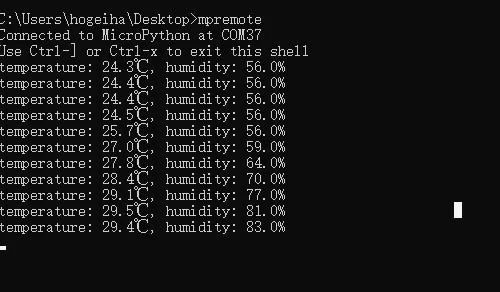
As you can see, the terminal prints the temperature and humidity collected by the sensor, and when our lighter is brought close, both the temperature and humidity change significantly:
C2019.MP4 88.0 MB
IV. Drivers
dht11_driver.zip 11 KB
5. BOM & Recommended Alternative Parts
None.
VI. Revision History
Document Version | Date of Revision | Modifier | Modified Content |
v1.0 | 2025-09-04 | ben0i0d | Initialize the document |
v1.1 | 2025-09-21 | Li Zisheng | Added Section 2.8 PCB Routing Notes Revised Section 3, Instructions for Circuit Source Engineering and Module Usage, and added a secondary heading: 3.1 Circuit Source Engineering, 3.2 Module Usage Instructions, 3.3 Application Experiments The BOM sheet has not been finally checked, the driver has not been re-verified, and the 3.3 application experiment Not yet specified. |
v1.2 | 2025-12-29 | Li Zisheng | Added application experiments and production files |
v1.3 | 2025-12-31 | Xin Ruili | Create an open version of the document based on the internal document version v1.2. |
v1.4 | 2026-03-29 | Xin Ruili | Modified the application experiment section |
VII. Relevant Materials
7.1 Chip Datasheet
DHT11 Datasheet.pdf 621 KB
7.2 PCB Silkscreen Specific Icons