Contents
- I. Module Introduction
- 2. Introduction to Main Chips
- 2.1 Chip Overview
- 2.2 Pin Definition
- 2.3 Functional Block Diagram
- 2.4 Performance Parameters
- 2.5 Reference Circuit
- 2.6 Chip Configuration
- 2.7 Communication Interfaces and Related Protocols
- 2.8 PCB Routing Precautions
- III. Circuit Engineering
- 3.1 Circuit Source Engineering
- 3.2 Module Usage Instructions
- 3.3 Application Experiment
- IV. Drivers
- 5. BOM & Recommended Alternative Parts
- VI. Revision History
- VII. Relevant Materials
- 7.1 Chip Datasheet
- 7.2 Unique Icons for PCB Silk Screen
I. Module Introduction
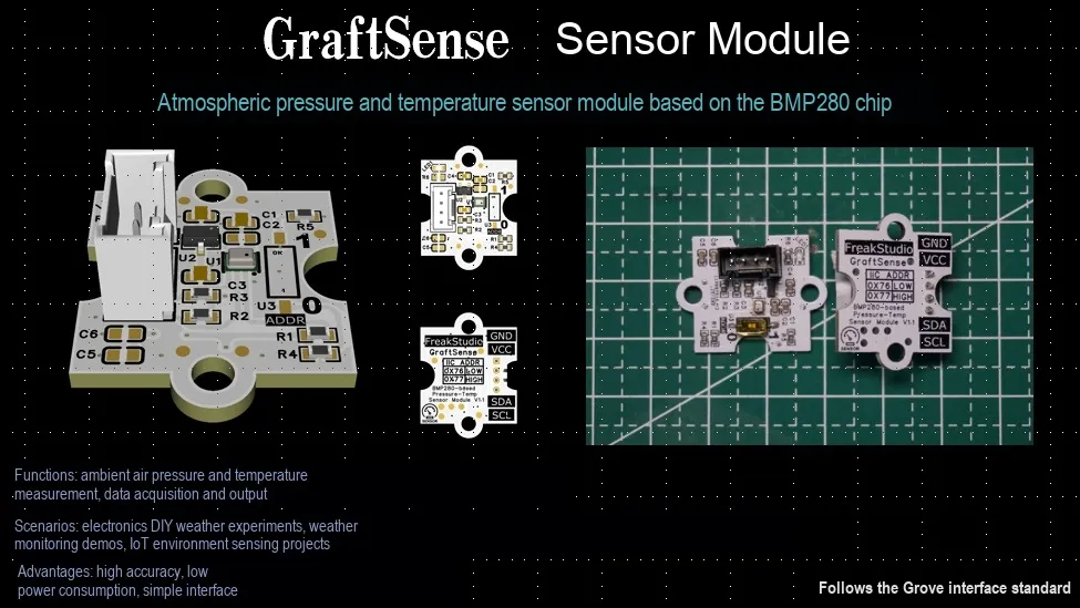
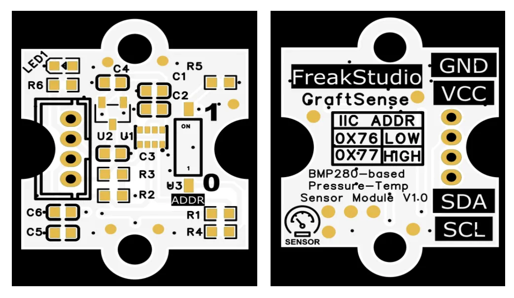
Atmospheric pressure and temperature sensor module based on BMP280 chip, adopting I2C communication interface (3.3V level), with a circuit input power supply voltage of 5V, powered by a DC-DC 5V to 3.3V conversion circuit, and equipped with an address selection circuit, MCU interface, power filtering and indicator light. This module can measure atmospheric pressure from 00 hPa to 1100 hPa (corresponding to an altitude range of -500m to 9000m), with an absolute accuracy of ±1 hPa, a relative accuracy of ±0.12 hPa, and a resolution of 0.16 Pa;Temperature measurement range: -40℃ to + 85℃, accuracy: ±1℃, resolution: 0.01℃. It is suitable for scenarios such as meteorological monitoring and altitude measurement, and provides a reliable hardware solution for accurate detection of atmospheric pressure and temperature.
2. Introduction to Main Chips
BMP280 is a low-power, high-precision digital barometric pressure and temperature sensor with a built-in piezoresistive pressure sensing element and ADC. It features a wide measurement range (300~1100 hPa for barometric pressure, -40℃~85℃ for temperature), with a barometric pressure accuracy of up to ±0.12 hPa and a temperature accuracy of ±0.5℃.It supports both I²C and SPI communication interfaces, is compatible with a 1.71V~3.6V power supply, features multiple power modes (normal / forced / sleep) with a sleep current of only 0.1μA, adopts a compact LGA-7 package, requires few peripheral components, and offers strong anti-interference performance. It is widely used in scenarios requiring accurate environmental Data Acquisition, such as weather monitoring, altitude measurement, smart wearables, and drones.
2.1 Chip Overview
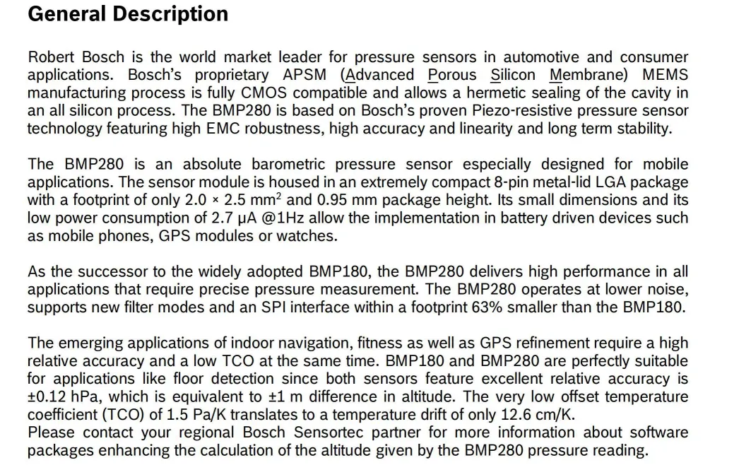
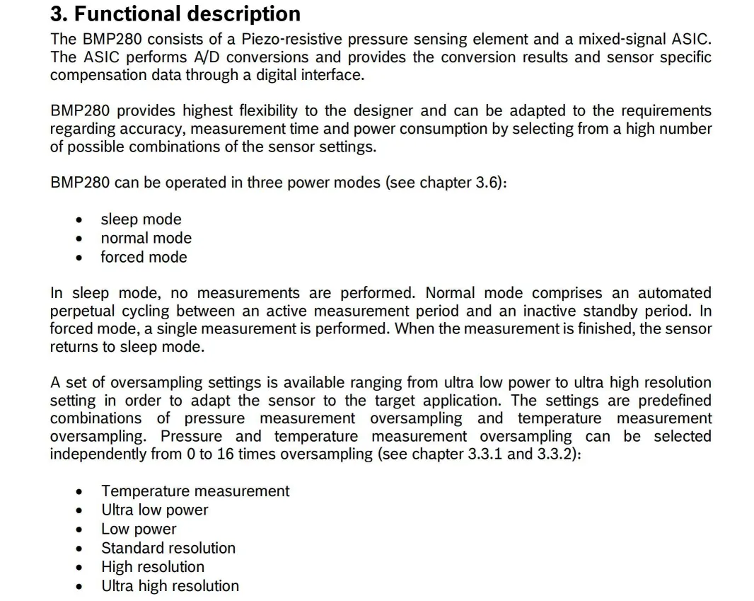
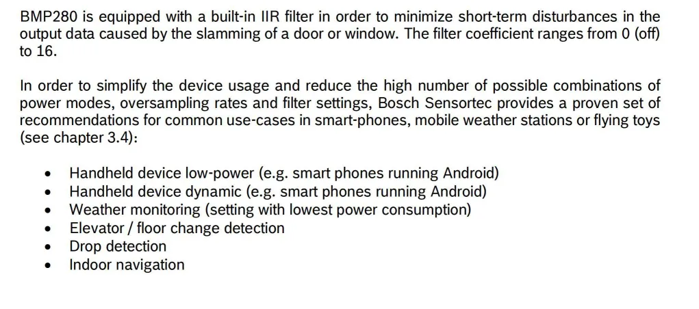
BMP280 is an absolute barometric pressure and temperature sensor launched by Bosch, which adopts piezoresistive sensing technology based on its APSM MEMS process, and comes in a compact 8-pin LGA package measuring 2.0×2.5mm². It features high EMC robustness, a high relative accuracy of ±0.1 hPa (equivalent to ±1 m in altitude) and low power consumption (only 2.7 μA at 1 Hz sampling), with a size 63% smaller than that of the BMP180;It integrates a piezoresistive sensing element and a mixed-signal ASIC, supports I2C / SPI interfaces, three power modes (sleep, normal, forced), as well as multi-range oversampling and IIR filter settings. It also provides preset configurations for scenarios such as smartphones and indoor navigation, and is suitable for battery-powered devices (e. g. mobile phones, GPS modules) and applications including floor detection and weather monitoring.
2.2 Pin Definition
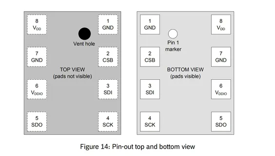
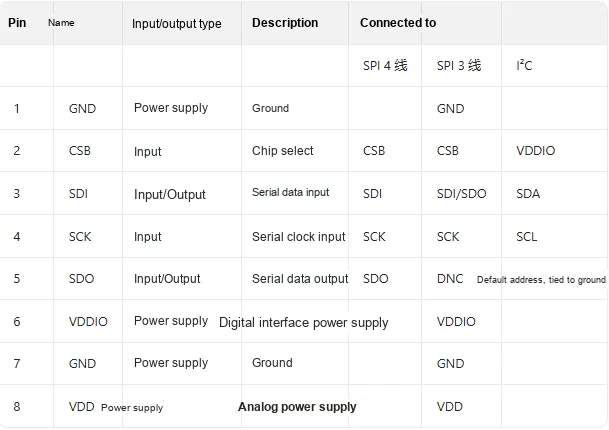
2.3 Functional Block Diagram
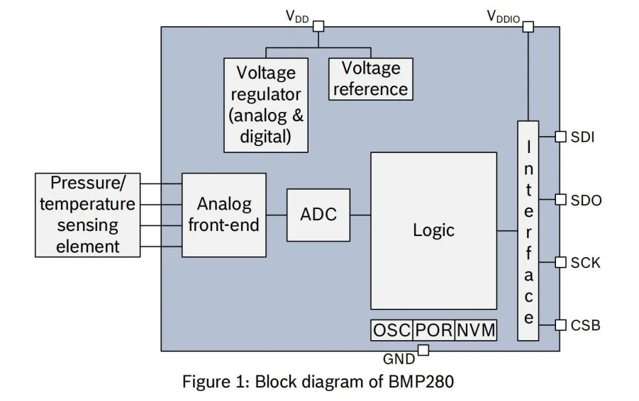
BMP280 functional block diagram is described as follows:
- Pressure/temperature sensing element (pressure/temperature sensing component): It senses the physical quantities of pressure and temperature in the environment and converts them into initial electrical signals.
- Analog Front-End and Conversion Module
- Analog Front-End (AFE): Conditions the initial electrical signal output by the sensing element (e. g., amplification, filtering, etc.) to make it compatible with the acquisition requirements of the subsequent ADC.
- ADC (Analog-to-Digital Converter): Converts the analog signal conditioned by the analog front end into a digital signal to provide digital input for subsequent logic processing.
- Power Supply and Reference Module
- Voltage regulator (analog & digital): It provides stable operating voltages for the analog and digital circuits inside the chip respectively to ensure stable power supply for each module.
- Voltage reference: It provides a precise reference voltage for modules such as ADC to ensure the accuracy of analog-to-digital conversion.
- Logic and Storage Module
- Logic (logic unit): It serves as the "brain" of the chip, responsible for processing the digital signals output by the ADC, performing algorithmic calculations for pressure and temperature, and generating the final measurement results.
- OSC (Oscillator), POR (Power-On Reset), NVM (Non-Volatile Memory): The oscillator provides clock signals, the power-on reset ensures initialization when the chip starts up, and the non-volatile memory stores key information such as calibration parameters.
Typical application scenarios for pressure and temperature measurement:
- Sensing and Conversion: Pressure/temperature sensing element senses pressure and temperature → Analog front-end conditions the signal → ADC converts the analog signal into a digital signal.
- Processing and Transmission: The Logic unit performs arithmetic operations on the digital signals to obtain the measured values of pressure and temperature, then transmits the measurement data to the external main controller via the SPI bus of the Interface port.
2.4 Performance Parameters
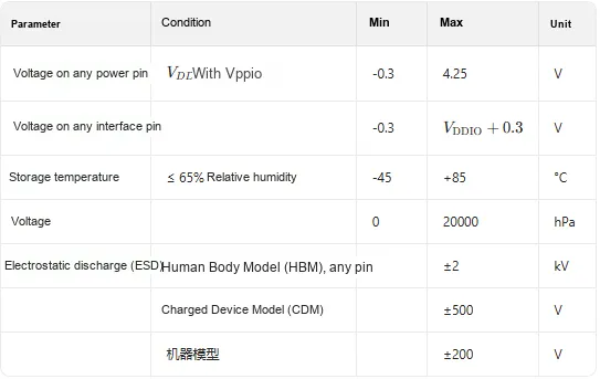
BMP280 has the following partial limiting parameters:
- Power supply pin voltage - 0.3~4.25V, Interface pin voltage - 0.3~ VDDIO + 0.3V;
- Storage temperature: -45 to + 85℃;
- Pressure 0~20000 hPa;
- Electrostatic Discharge (ESD): Human Body Model ±2kV, Charged Device Model ±500V, Machine Model ±200V.
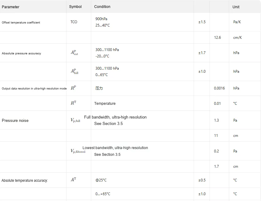
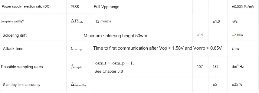
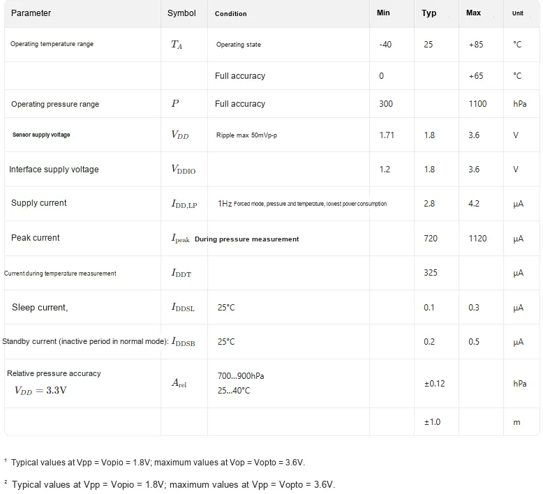
BMP280 has the following partial electrical parameters:
- Operating Temperature Range -40 to + 85°C (operating state), 0 to + 65°C (full accuracy);
- Working pressure range: 300~1100 hPa;
- Sensor supply voltage 1.71~3.6V, Interface supply voltage 1.2~3.6V;
- Supply current typically 2.8~4.2μA (1Hz forced mode), peak current 720~1120μA (during pressure measurement), sleep current 0.1~0.3μA, standby current 0.2~0.5μA.
- Accuracy and resolution:
- Relative pressure accuracy: ±0.12 hPa (equivalent to ±1.0 m);
- Absolute pressure accuracy: ±1.7 hPa (-20 to 0℃), ±1.0 hPa (0 to 65℃);
- Temperature accuracy ±0.5℃(at 25℃), ±1.0℃(within 0~65℃);
- Pressure resolution 0.0016 hPa, temperature resolution 0.01℃.
- Power Supply Rejection Ratio ±0.005 Pa/mV;
- Long-term stability: ±1.0 hPa (12 months);
- Welding drift: -0.5 to + 2 hPa;
- Startup time 2ms;
- Sampling rate 157~182 Hz.
2.5 Reference Circuit
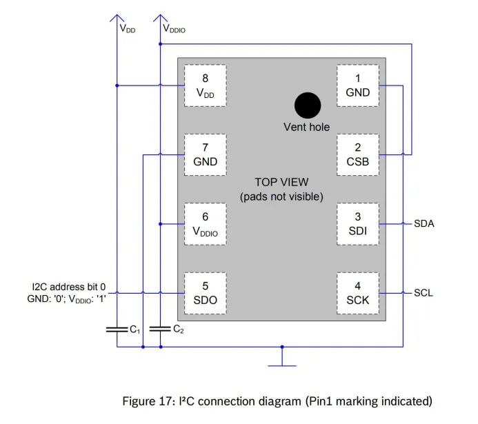
This is the reference connection circuit of BMP280 : marked with pin 1-8 function, pin 5 ( SDO ) can be configured by connecting GND or VDDIO (with C1 / C2 ) I2C address bit (ground is "0", connected to VDDIO is "1"), and the external signal connection corresponding to each pin is clearly defined. It is the pin connection and address configuration reference circuit of BMP280 .
2.6 Chip Configuration
None.
2.7 Communication Interfaces and Related Protocols
2.7.1 Register Description
2.7.1.1 Operation Mode
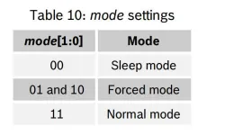
The BMP280 can operate in three power modes:
- Sleep Mode
- Normal Mode
- Mandatory Mode
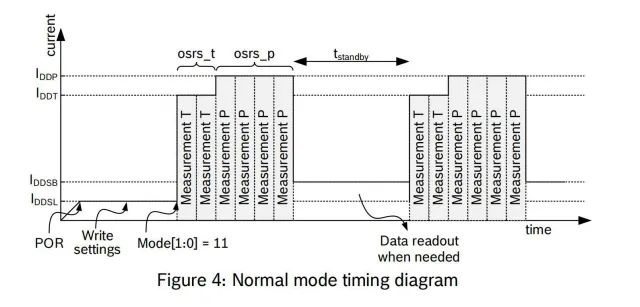
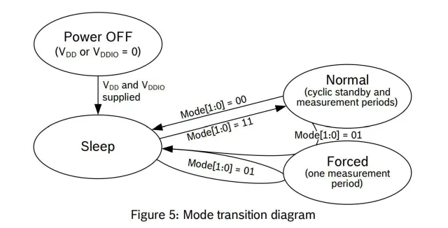
In sleep mode, no measurements are performed. Normal mode involves a continuous automatic cycle between active measurement periods and inactive standby periods. In forced mode, a single measurement is performed. After the measurement is completed, the sensor returns to sleep mode.
A range of oversampling settings are available, spanning from ultra-low power to ultra-high resolution configurations to adapt the sensor to the target application. These settings are predefined combinations of pressure measurement, temperature measurement and oversampling. Pressure and temperature measurements can be selected independently, with an oversampling count ranging from 0 to 16.
These modes can be selected by controlling the mode [1:0] bits in the control register 0xF4.
2.7.1.1 Sleep Mode
After power-on reset, the device is defaulted to sleep mode. In sleep mode, no measurement is performed, and the power consumption (IDSSM) is minimized. All registers are accessible; the chip ID and the forced mode compensation coefficient in Section 3.6.2 can be read.
2.7.1.2 Forced Mode
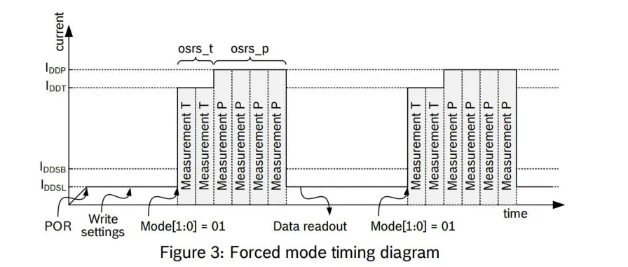
In forced mode, a single measurement is performed in accordance with the selected measurement and filter options. When the measurement is finished, the sensor returns to sleep mode, and the measurement result can be obtained from the data register. To perform the next measurement, you need to select forced mode again. This operation is similar to that of the BMP180. Forced mode is recommended for applications that require a low sampling rate or host-based synchronization.
2.7.1.3 Normal Mode
Normal mode continuously cycles between an (active) measurement phase and an (inactive) standby phase, where the standby duration is defined by tstandby. The current during the standby phase (IDDSB) is slightly higher than that in sleep mode. After configuring the mode, measurement and filter options, the latest measurement results can be retrieved from the data register without further write operations. Normal mode is recommended when using an IIR filter, and is suitable for applications that require filtering out short-term disturbances, such as wind blowing on the sensor.
2.7.1.4 Standby Time
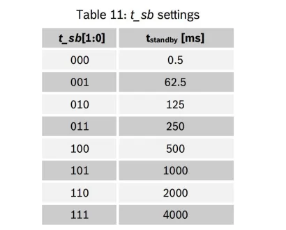
The standby time is determined by the content of the t_sb[2:0] bits in the control register 0xF5 according to the following table:
2.7.1.5 Mode Transition Diagram
The supported mode transitions are demonstrated below. If the device is currently performing a measurement, the execution of the mode switch command will be delayed until the ongoing measurement cycle is completed. All other mode switch commands will be ignored until the last issued mode switch command is fully executed. Mode transitions other than those listed below have undergone stability testing, but this does not mean they are the recommended operating modes for the device.
2.7.1.6 Current Consumption
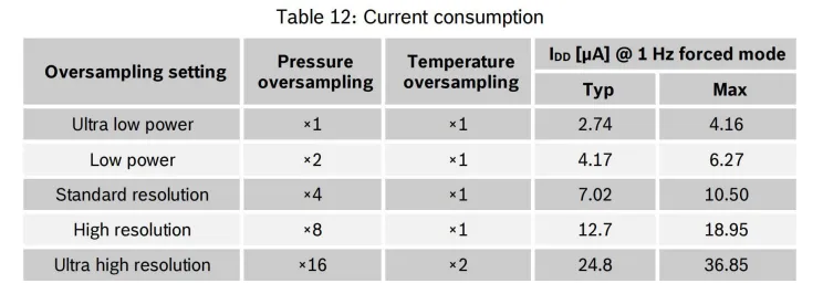
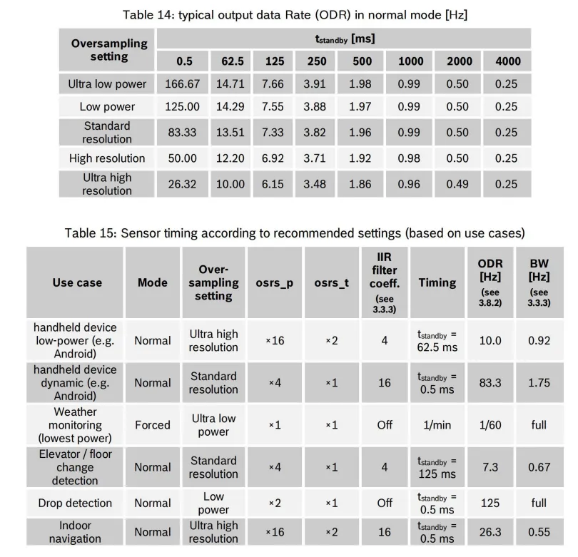
Current consumption depends on the output data rate (ODR) and oversampling settings. The values below have been normalized to an ODR of 1 Hz. The actual consumption at a given ODR can be calculated by multiplying the consumption values in Table 12 by the applied ODR. The actual ODR is defined by the frequency of forced measurements set by the user, or by the oversampling and tstandby settings in normal mode, as detailed in Table 14.
2.7.2 Measurement Sequence
In forced mode, the measurement execution rate depends on the oversampling settings osrs_t and osrs_p. In normal mode, the measurement execution rate depends on the oversampling settings osrs_t, osrs_p and the standby time tstandby. The table below provides the corresponding output data rate (ODR) only for the recommended oversampling combinations.
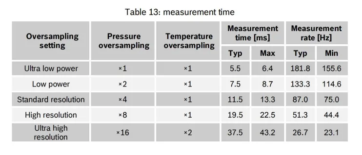
2.7.2.1 Measurement Time
The table below illustrates the typical and maximum measurement times based on the selected oversampling settings. The minimum achievable frequency is determined by the maximum measurement time.
2.7.2.2 Measurement Rate in Normal Mode
The table below illustrates the expected measurement rate in normal mode based on oversampling settings and tstandby.
2.7.3 Pressure Measurement
Pressure measurement can be enabled or skipped. If the BMP280 is used as a temperature sensor, skipping the measurement is useful. When enabled, multiple oversampling options are available. Each oversampling step reduces noise and increases the output resolution by 1 bit, which is stored in the XLSB data register 0xF9. The enable/disable of measurement and oversampling settings are selected via the osrs_p [2:0] bits in the control register 0xF4.
Table 4: osrs_p Settings
| Oversampling Setting | Pressure Oversampling | Typical Pressure Resolution | Recommended Temperature Oversampling |
| Pressure measurement skipped | Skipped (output set to 0x80000) | – | On demand |
| Ultra low power | ×1 | 16-bit / 2.62 Pa | ×1 |
| Low power | ×2 | 17-bit / 1.31 Pa | ×1 |
| Standard resolution | ×4 | 18-bit / 0.66 Pa | ×1 |
| High resolution | ×8 | 19-bit / 0.33 Pa | ×1 |
| Ultra high resolution | ×16 | 20-bit / 0.16 Pa | ×2 |
2.7.4 Temperature Measurement
Temperature measurement can be enabled or skipped. To measure pressure extremely quickly, skipping the measurement is useful. When enabled, multiple oversampling options are available. Each oversampling step reduces noise and increases the output resolution by 1 bit, which is stored in the XLSB data register 0xFC. The enable/disable and oversampling settings for temperature measurement are selected via the osrs_t [2:0] bits in control register 0xF4.
Table 5: osrs_t Settings
| osrs_t[2:0] | Temperature oversampling | Typical temperature resolution |
| 0 | Skipped (output set to 0x80000) | – |
| 1 | ×1 | 16-bit / 0.0050 °C |
| 10 | ×2 | 17-bit / 0.0025 °C |
| 11 | ×4 | 18-bit / 0.0012 °C |
| 100 | ×8 | 19-bit / 0.0006 °C |
| 101, 110, 111 | ×16 | 20-bit / 0.0003 °C |
It is recommended to determine the value of osrs_t based on the selected osrs_p value in Table 4. Temperature oversampling higher than ×2 is feasible, but it will not further significantly improve the accuracy of the pressure output, because the noise of the compensated pressure value depends more on the original pressure rather than the original temperature noise. Following the recommended settings will yield the optimal noise-power consumption ratio.
2.7.5 IIR Filter
Environmental pressure can experience numerous short-term variations due to factors such as opening and closing doors or windows, and wind blowing toward the sensor. To suppress these disturbances in the output data without incurring additional interface traffic and processor workload, the BMP280 is equipped with an internal IIR filter, which can effectively reduce the bandwidth of the output signal. The output of the next measurement step follows the formula below:

Among them, data_filtered_old refers to the data from the previous acquisition, and data_ADC is the data from the ADC before IIR filtering.
The IIR filter can be configured via the filter[2:0] bits in control register 0xF5, with the specific options as follows:
To find the appropriate filter settings, please refer to Section 2.7.4.
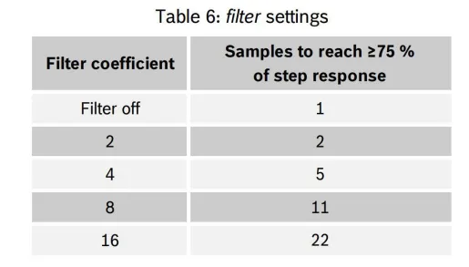
When writing to the filter register, the filter is reset. The next value will pass through the filter and become the initial memory value of the filter. If temperature or pressure measurement is skipped, the corresponding filter memory will remain unchanged even if the output register is set to 0x80000. When the previously skipped measurement is re-enabled, the output will be filtered using the filter memory from the last non-skipped measurement.
2.7.6 Filter Selection
To select the optimal settings, it is recommended to refer to the following use cases:
Table 7: Use Case-Based Recommendation Filter Settings
| Use case | Mode | Oversampling Setting | osrs_p | osrs_t | IIR filter coefficient (see 3.3.3) | I₀D [μA] (see 3.7) | ODR [Hz] (see 3.8.2) | RMS noise [cm] (see 3.5) |
| Handheld device, low power (e.g., Android) | Normal | Ultra high resolution | ×16 | ×2 | 4 | 247 | 10 | 4 |
| Handheld device, dynamic (e.g., Android) | Normal | Standard resolution | ×4 | ×1 | 16 | 577 | 83.3 | 2.4 |
| Weather monitoring (lowest power) | Forced | Ultra low power | ×1 | ×1 | Off | 0.14 | 1/60 | 26.4 |
| Elevator / floor change detection | Normal | Standard resolution | ×4 | ×1 | 4 | 50.9 | 7.3 | 6.4 |
| Drop detection | Normal | Low power | ×2 | ×1 | Off | 509 | 125 | 20.8 |
| Indoor navigation | Normal | Ultra high resolution | ×16 | ×2 | 16 | 650 | 26.3 | 1.6 |
2.7.7 Noise
The noise depends on the selected oversampling and filter settings. The listed values are determined in a controlled pressure environment, based on the average standard deviation of 32 consecutive measurement points acquired at the maximum sampling rate. This is done to exclude long-term drift from the noise measurement.
Table 8: Pressure Noise
| Oversampling Setting | Typical pressure RMS noise [Pa] - IIR filter coefficient | ||||
| off | 2 | 4 | 8 | 16 | |
| Ultra low power | 3.3 | 1.9 | 1.2 | 0.9 | 0.4 |
| Low power | 2.6 | 1.5 | 1 | 0.6 | 0.4 |
| Standard resolution | 2.1 | 1.2 | 0.8 | 0.5 | 0.3 |
| High resolution | 1.6 | 1 | 0.6 | 0.4 | 0.2 |
| Ultra high resolution | 1.3 | 0.8 | 0.5 | 0.4 | 0.2 |
Table 9: Temperature Noise
| Temperature oversampling | Typical temperature RMS noise [°C] - IIR filter off |
| Oversampling ×1 | 0.005 |
| Oversampling ×2 | 0.004 |
| Oversampling ×4 | 0.003 |
| Oversampling ×8 | 0.003 |
| Oversampling ×16 | 0.002 |
2.7.2 IIC Communication Protocol
The BMP280 supports both I²C and SPI digital interfaces, and functions as a slave device in both protocols. The I²C interface supports standard mode, fast mode and high-speed mode. The SPI interface supports mode "00"(CPOL = CPHA = '0') and mode "11"(CPOL = CPHA = '1') in both 4-wire and 3-wire configurations.
The following content only introduces the information related to I²C communication, and for SPI communication, please refer to the content in the attached datasheet.
The following transactions are supported:
- Single-byte write
- Multi-byte write (using register address and register data pairs)
- Single-byte Read
- Multi-byte read (using a single register address with auto-increment)
2.7.2.1 Interface Selection
Interface selection is automatically completed based on the CSB (Chip Select) status. If CSB is connected to VDDIO, the I²C interface is activated; if CSB is pulled low, the SPI interface is activated. Once CSB is pulled low (regardless of whether a clock cycle occurs), the I²C interface will be disabled until the next power-on reset. This is done to avoid misdecoding SPI communication as I²C data. Since power-on reset is only performed when both VDD and VDDIO are established, there is no power supply detection during power-up, so caution is required during use.However, if you want to use I²C and the CSB pin is not directly connected to VDDIO but instead connected via a programmable pin, you must ensure that this pin has output the VDDIO level during the device's power-on reset. If this condition is not met, the device will be locked in SPI mode and will not respond to I²C commands.
2.7.2.2 I²C Interface
The I²C slave interface is compatible with the Philips I²C specification version 2.1. Refer to Table 27 for detailed timing. All modes (standard, fast, and high-speed) are supported. SDA and SCL are not pure open-drain structures; both pads incorporate ESD protection diodes connected to VDDIO and GND. Since the device does not perform clock stretching, the SCL structure is a high-impedance input with no pull-down capability.
The 7-bit device address is 111011x. The first 6 most significant bits (MSBs) are fixed, and the last bit can be changed via the value of SDO and modified during operation. When SDO is connected to GND, the slave address is 1110110 (0x76); when connected to VDDIO, the slave address is 1110111 (0x77), which matches the I²C address of the BMP180. The SDO pin must not be left floating; if it is left floating, the I²C address will be undefined.
The I²C interface uses the following pins:
- SCK: Serial Clock (SCL)
- SDI: Data (SDA)
- S DO: From the least significant bit of the address (GND = '0', VDDIO = '1')
To select the I²C interface, CSB must be connected to VDDIO. SDI is bidirectional and connected to GND in an open-drain configuration: it must be externally connected to VDDIO via a pull-up resistor. Refer to Chapter 6 for connection instructions.
2.7.2.3 I²C Write
A write operation is performed by transmitting the slave address in write mode (RW = '0'), which generates the slave address 111011X0 ('X' is determined by the state of the SDO pin). The master then sends register address and register data pairs. The transaction is terminated with a stop condition, as shown in Figure 7.
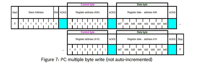
2.7.2.4 I²C Read
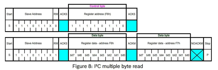
To read a register, the register address must first be sent in write mode (starting with address 111011X0). A stop condition or a repeated start condition must then be generated. After that, the slave is addressed in read mode (RW = '1') at address 111011X1, and subsequently the slave transmits data from the auto-incrementing register address until a not acknowledge (NOACK) and a stop condition occur. This is illustrated in Figure 8, where two bytes are read from registers 0xF6 and 0xF7.
2.8 PCB Routing Precautions
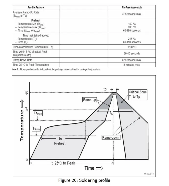
There are no special requirements for the PCB routing of this module, and the following is the soldering instructions:
The humidity sensitivity rating of the BMP280 sensor conforms to JEDEC Level 1, see also:
- IPC/JEDEC J-STD-020C *Joint Industry Standard: Moisture/Reflow Sensitivity Classification for Non-Hermetic Solid State Surface Mount Devices*
- IPC/JEDEC J-STD-033A *Joint Industry Standard: Handling, Packaging, Shipping and Use of Moisture/Reflow Sensitive Surface Mount Devices*
This sensor meets the lead-free soldering requirements of the aforementioned IPC/JEDEC standards, meaning the maximum peak temperature for reflow soldering can reach up to 260°C. The minimum height of the solder after reflow shall be at least 50μm, which is intended to achieve good mechanical decoupling between the sensor device and the printed circuit board (PCB).
III. Circuit Engineering
3.1 Circuit Source Engineering
To obtain the source project of the circuit, please follow the official account [Freak Embedded]
3.2 Module Usage Instructions
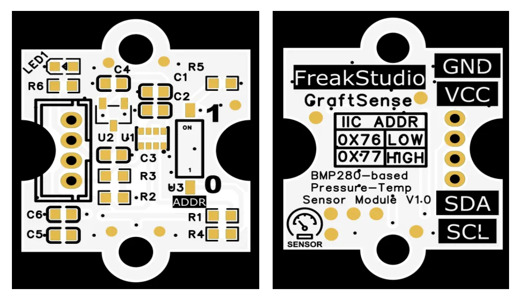
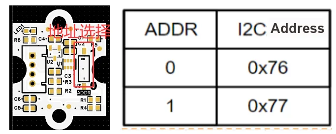
This module provides an I2C communication interface: it supports standard I2C communication baud rates, and can flexibly configure 2 types of I2C device addresses via the ADDR selection bit (LOW corresponds to 0X76, HIGH corresponds to 0X77), is compatible with 3.3V/5V logic levels, can stably realize high-precision acquisition and reading of ambient temperature and atmospheric pressure data, and is applicable to scenarios such as environmental monitoring for maker projects, meteorological parameter acquisition for embedded devices, and temperature and pressure sensing for small IoT devices.
The SDA pin of the module corresponds to the I2C data transmission terminal, and the SCL pin corresponds to the I2C clock synchronization terminal, which needs to be connected correspondingly to the I2C interface of the main control device;The ADDR selection bit configures the address through level switching, which supports up to 2 modules to be mounted on the same I2C bus at the same time (it is necessary to ensure a unique address) to ensure collaborative Data Acquisition of multiple devices.
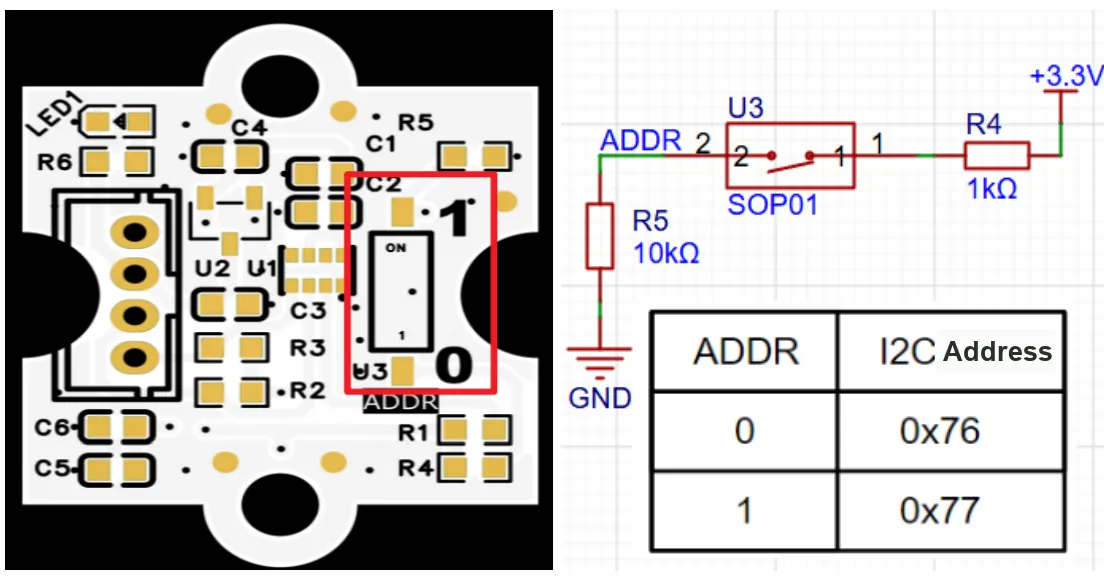
The IIC address of BMP280 can be selected via the DIP switch. The truth tables for the physical device and the schematic diagram are as follows:
3.3 Application Experiment
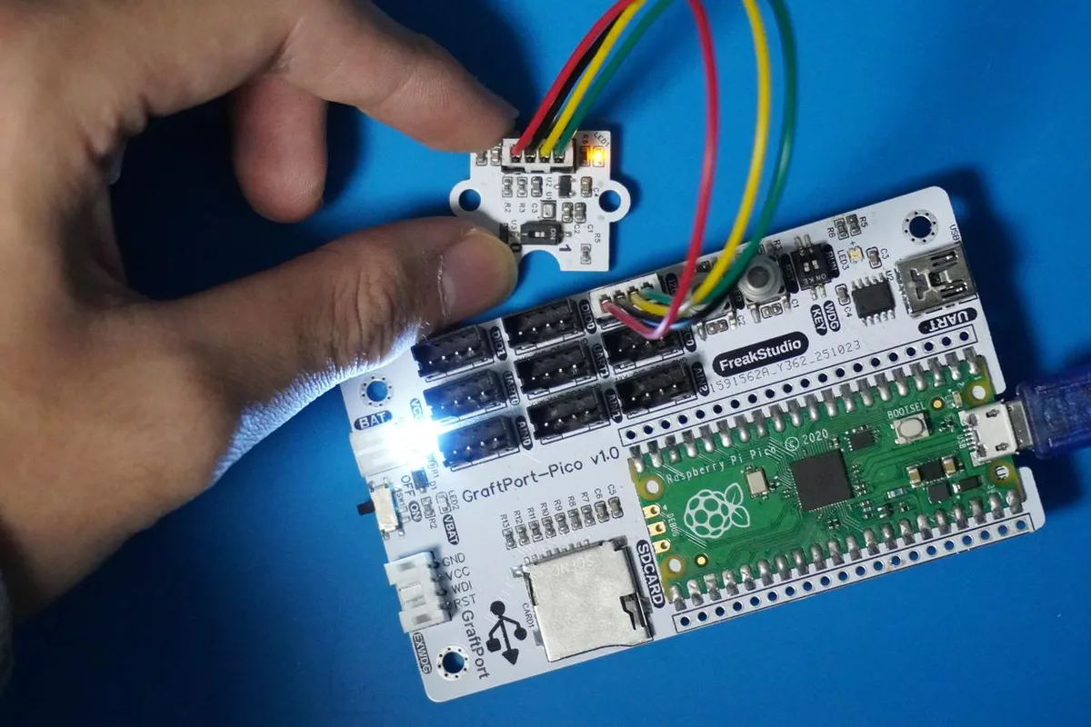
Here, we use the GraftPort-RP2040 development board for testing, and connect the atmospheric pressure and temperature sensor module based on the BMP280 chip to communicate with the main controller via the I2C interface.
Here, we need to set the address bits in advance via a DIP switch by soldering:(select 0x76 here)
Here, we first use the HY2.0-4P connection cable to connect the module to the GraftPort-RP2040 development board's I2C1 interface:
The module connections are shown in the following table:
Development Board Pins | Module Pins | Description |
Pin 2 |
|
|
Pin 3 |
|
|
Here, we need to search for the relevant driver packages on uPyPI: https://upypi.net/zh/
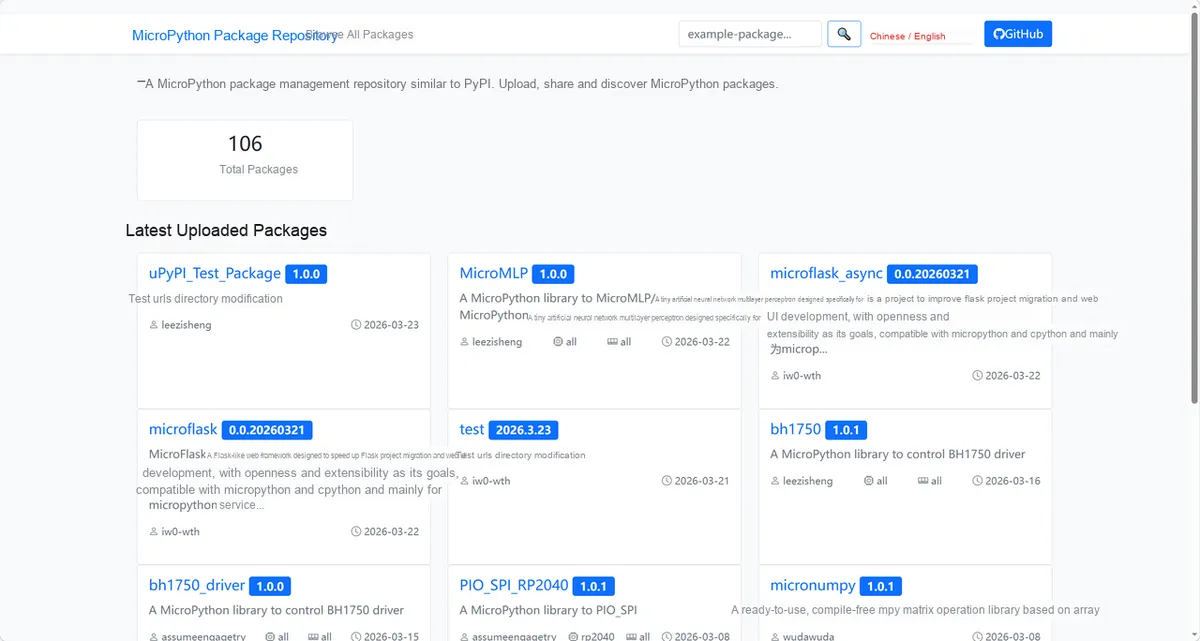
Enter bmp280_driver to search, and the following will be displayed:
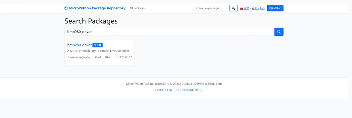
Click to copy the local installation command:
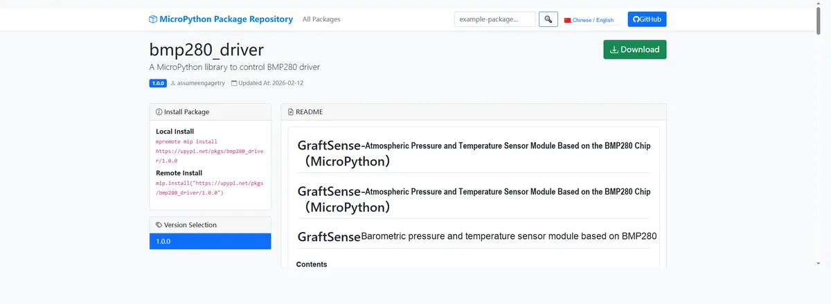
Here, we can import the module driver library code via the mip tool. The usage commands for the mpremote tool are as follows:
mpremote mip install github:FreakStudioCN/GraftSense-Drivers-MicroPython/sensors/bmp280_driverImport the BMP280 chip-based atmospheric pressure and temperature sensor module - MicroPython driver code, then copy the following main.py code into our project:
# Python env   : MicroPython v1.23.0
# -*- coding: utf-8 -*-
# @Time    : 2025/9/9 AM 11:25
# @Author  : 缪贵成
# @File    : main.py
# @Description : BMP280-based atmospheric pressure, temperature and humidity sensor module driver test program

# ======================================== Import Modules =========================================

import time
from machine import I2C
from bmp280_float import BMP280

# ======================================== Global Variables =============================================

bmp_addr = None

# ======================================== Functions =============================================

# ======================================== Custom Classes =============================================

# ======================================== Initialization Configuration ============================================

time.sleep(3)
print("FreakStudio:Testing BMP280 pressure, temperature, and humidity sensor")
# Note: Modify the pin numbers according to the actual hardware
i2c = I2C(1, scl=3, sda=2, freq=100000)
# Start scanning for devices on the I2C bus and return a list of slave addresses
devices_list:list[int] = i2c.scan()
print('START I2C SCANNER')
# If the devices list is empty, no device is connected to the I2C bus
if len(devices_list) == 0:
    # If not empty, print the slave device addresses
    print("No i2c device !")
else:
    print('i2c devices found:', len(devices_list))
for device in devices_list:
    if 0x60 <= device <= 0x7A:
        print("I2c hexadecimal address:", hex(device))
        bmp_addr = device

bmp = BMP280(i2c=i2c, address=bmp_addr)

# ======================================== Main Program ===============================================
try:
    print("FreakStudio: Testing BMP280 sensor (Temperature, Humidity, Pressure)")
    while True:
        # Get floating-point temperature, humidity and air pressure
        temp, press, hum = bmp.read_compensated_data()
        # Convert the air pressure unit to hPa (1 hPa = 100 Pa)
        press_hpa = press / 100.0
        # Calculate the altitude
        sea_level_hpa = 1013.25
        altitude = 44330.0 * (1.0 - (press_hpa / sea_level_hpa) ** 0.1903)
        # Print the floating-point information
        print("Temperature: {:.2f} °C | Humidity: {:.2f}% | Pressure: {:.2f} hPa".format(
            temp, hum, press_hpa
        ))
        print(altitude)
        time.sleep(2)
except KeyboardInterrupt:
    print("\nTest stopped")
To flash the code, open a terminal and use the mpremote tool to connect to the main controller; the output is as follows:
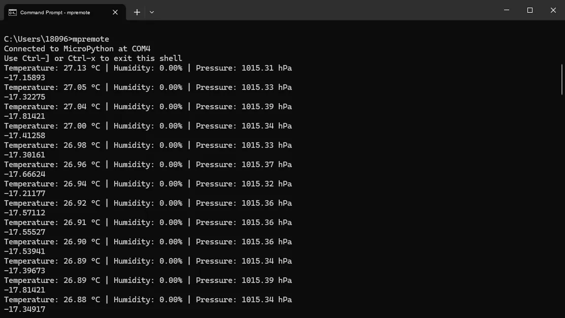
You can see the air pressure and temperature data monitored by the sensor output in the terminal.
IV. Drivers
bmp280_driver.zip 13 KB
5. BOM & Recommended Alternative Parts
None.
VI. Revision History
Document Version | Date of Revision | Modifier | Modified Content |
v1.0 | 2025-11-17 | Ling Gaoxing | Initialize the document |
v1.1 | 2025-12-29 | Li Zisheng | Added application experiments and production files |
v1.2 | 2025-12-31 | Xin Ruili | Create an open version of the document based on the internal document version v1.1. |
v1.3 | 2026-03-29 | Xin Ruili | Modified the application experiment section |
VII. Relevant Materials
7.1 Chip Datasheet
BMP280 Datasheet.pdf 26.3 MB
7.2 Unique Icons for PCB Silk Screen