
Contents
- Introduction
- I. Module Introduction
- II. Introduction to Major Chips
- 2.1 Chip Overview
- 2.2 Pin Definition
- 2.3 Functional Block Diagram
- 2.4 Performance Parameters
- 2.5 Reference Circuit
- 2.6 Chip Configuration
- 2.7 Communication Interfaces and Related Protocols
- 2.8 Register Definition
- III. Circuit Engineering
- 3.1 Circuit Source Engineering
- 3.2 Module Usage Instructions
- 3.3 Application Experiment
- 4. Drivers
- 5. BOM & Recommended Alternative Parts
- VI. Revision History
- VII. Relevant Materials
Introduction
In scenarios such as data centers, power cabinets, underground pipe galleries, and smart homes, water leakage detection serves as a critical line of defense to ensure equipment safety and building structure integrity. However, traditional conductive water immersion sensors have long been plagued by the persistent pain points of "prone to corrosion, high error rate, and high maintenance cost": metal electrodes are easily oxidized and corroded when exposed to humid environments for a long time, the difference in conductivity of different water qualities leads to unstable detection, and they can only detect between two points, resulting in blind spots for leakage points.
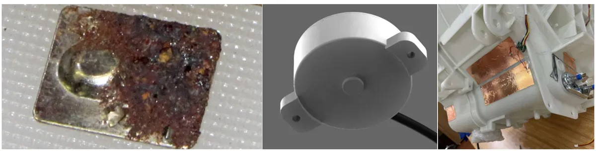
Traditional conductive immersion water sensors rely on direct contact between electrodes and water, which has many insurmountable drawbacks:
- Prone to corrosion and short service life: As metal electrodes are highly susceptible to oxidation and corrosion when exposed to water and humid air over long periods, this will lead to detection failure and require frequent replacement and maintenance;
- High error rate and greatly affected by water quality: Water quality, scale, salt content and other factors will change the conductivity of water, leading to unstable detection results, and damp condensation can also easily trigger false alarms;
- Many detection blind spots and no positioning capability: It only supports switch value detection between two points, cannot cover large areas, and is unable to locate water leakage points, resulting in low troubleshooting efficiency;
- Numerous installation restrictions: The waterproof structure of the equipment must be damaged to install the electrodes, so it is not suitable for closed containers or decorated scenarios.
The capacitive water immersion module is precisely a new generation of detection solution designed to address these pain points.

Scenarios such as underground utility tunnels and tunnels are susceptible to surface water or groundwater, with hidden and highly hazardous water leakage risks. The WS11 can be deployed at key positions in utility tunnels and tunnels to monitor water level changes in real time, issue an immediate alarm when an abnormality occurs, and activate the drainage system or implement countermeasures. The module supports cascade expansion, enabling multi-point water leakage detection and positioning, which helps management personnel respond quickly, reduce losses, and improve the operational safety of infrastructure.
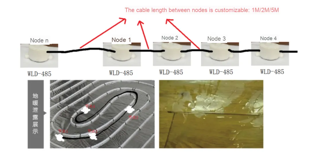
In Data centers, communication data centers and power cabinets, the WS11 can be installed at the bottom of equipment or inside cabinets to monitor water leakage in real time. Once a leak occurs, the module can quickly detect it and output a signal to trigger an alarm or linked power-off, preventing equipment short circuits and fire risks caused by water damage. Its non-contact design eliminates the need for frequent maintenance, allowing it to operate stably for long periods in humid data center environments and provide round-the-clock safety protection for critical equipment.

In smart homes, the WS11 can be installed in leak-prone locations such as kitchens, bathrooms, and water pipe connections to monitor leaks in real time and notify users promptly. In building constructions, it can monitor issues like pipe rupture and air conditioning condensate leakage, reducing water damage to building structures and cutting maintenance costs. Its non-contact installation won't compromise the aesthetic of interior decoration, and its low-power design also meets the long-lasting battery life requirements of smart home devices.
I. Module Introduction
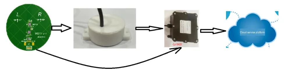
WS61 (Water Sensor-MCP61) is an intelligent capacitive, non-contact water immersion sensor. It adopts a new generation of capacitive sensing microprocessor SOC chip launched by Minyuan Sensing, integrates a dual-channel capacitive analog front-end sensing circuit (AFE CAP), and is equipped with a high-precision temperature chip. It outputs capacitive information through the UART interface for algorithm analysis, which effectively filters out interferences such as vibration and condensation, realizes accurate distinction between water presence/absence and different states, and can simultaneously provide ambient temperature information.
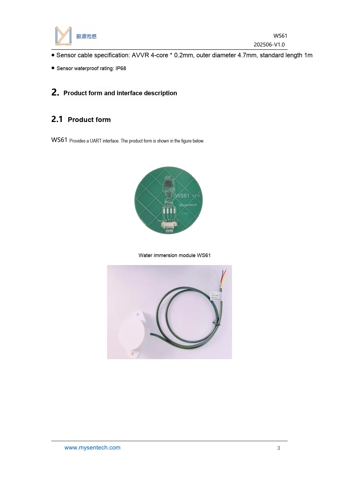
Product Form, cable specifications and basic appearance information of the WS61 water immersion sensor.
- WS61 is a capacitive, non-contact sensing intelligent water immersion sensor;
- Compared with the traditional conductivity-based solution, it features a large detection range, high reliability, and low susceptibility to water quality impacts.
- It supports continuous digital quantity analysis and cascaded positioning, making it suitable for scenarios such as water leakage monitoring and ponding detection.
UART interface is provided by default, and the protection rating of the sensor can reach IP68.
II. Introduction to Major Chips
2.1 Chip Overview
WS61 adopts the capacitive non-contact measurement principle to determine the water immersion state by detecting changes in dielectric constant, and can simultaneously output capacitance value, temperature and alarm status.
2.2 Pin Definition
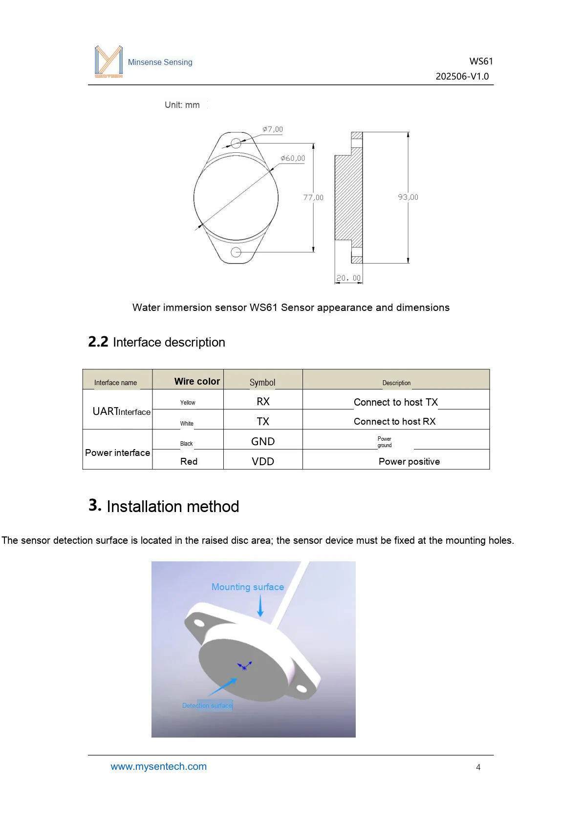
This figure illustrates the physical dimensions and interface definitions of the WS61 to facilitate installation and wiring.
2.3 Functional Block Diagram
None.
2.4 Performance Parameters
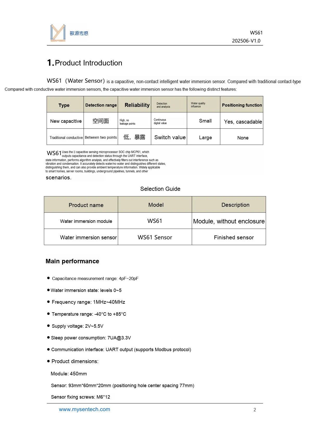
This diagram illustrates the performance parameters of the WS61
2.5 Reference Circuit
None.
2.6 Chip Configuration
None.
2.7 Communication Interfaces and Related Protocols
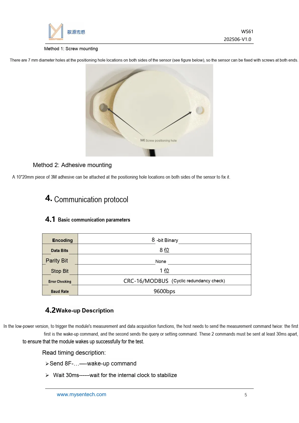
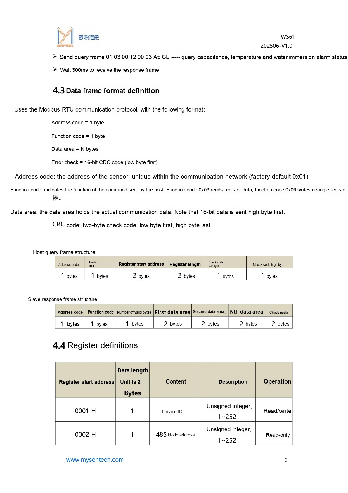
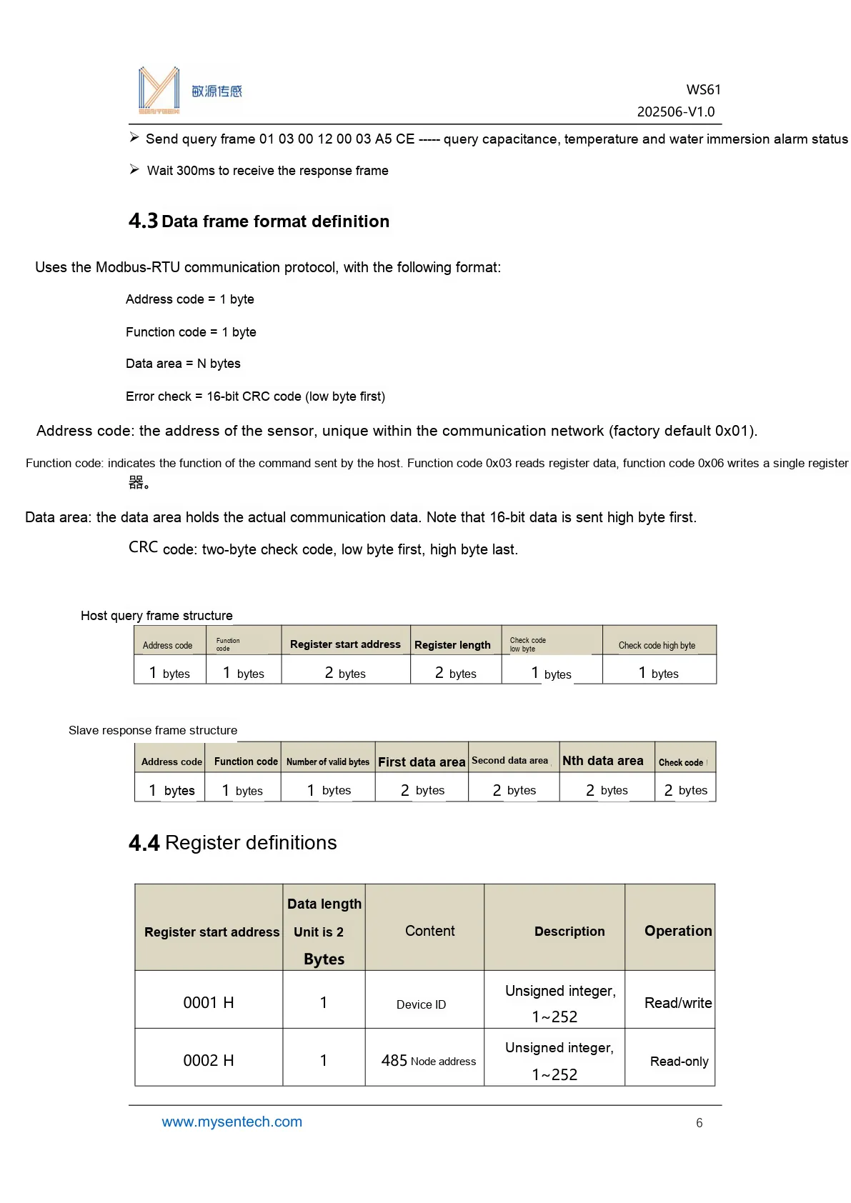
This diagram illustrates the Modbus-RTU data frame format of the WS61 and the definition of its first half registers.
2.8 Register Definition
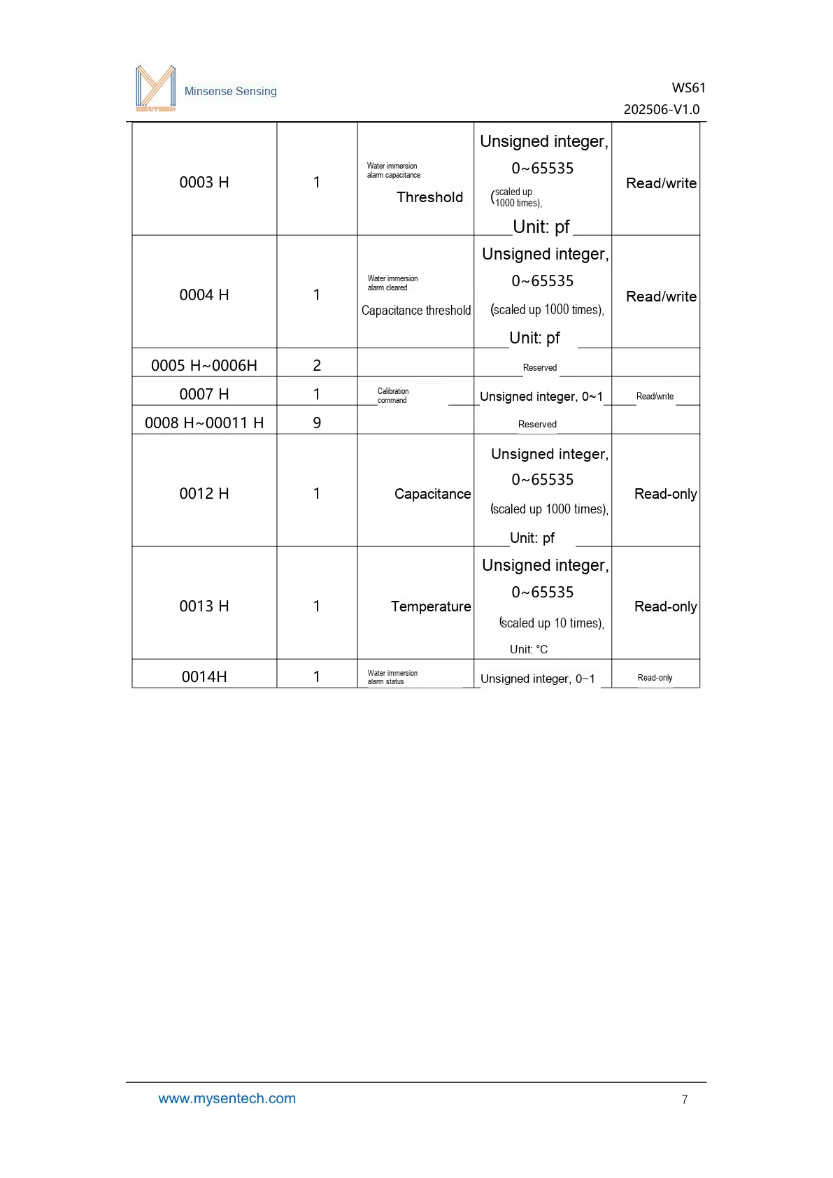
This figure lists the registers related to the alarm threshold of WS61 and the corresponding data meanings.
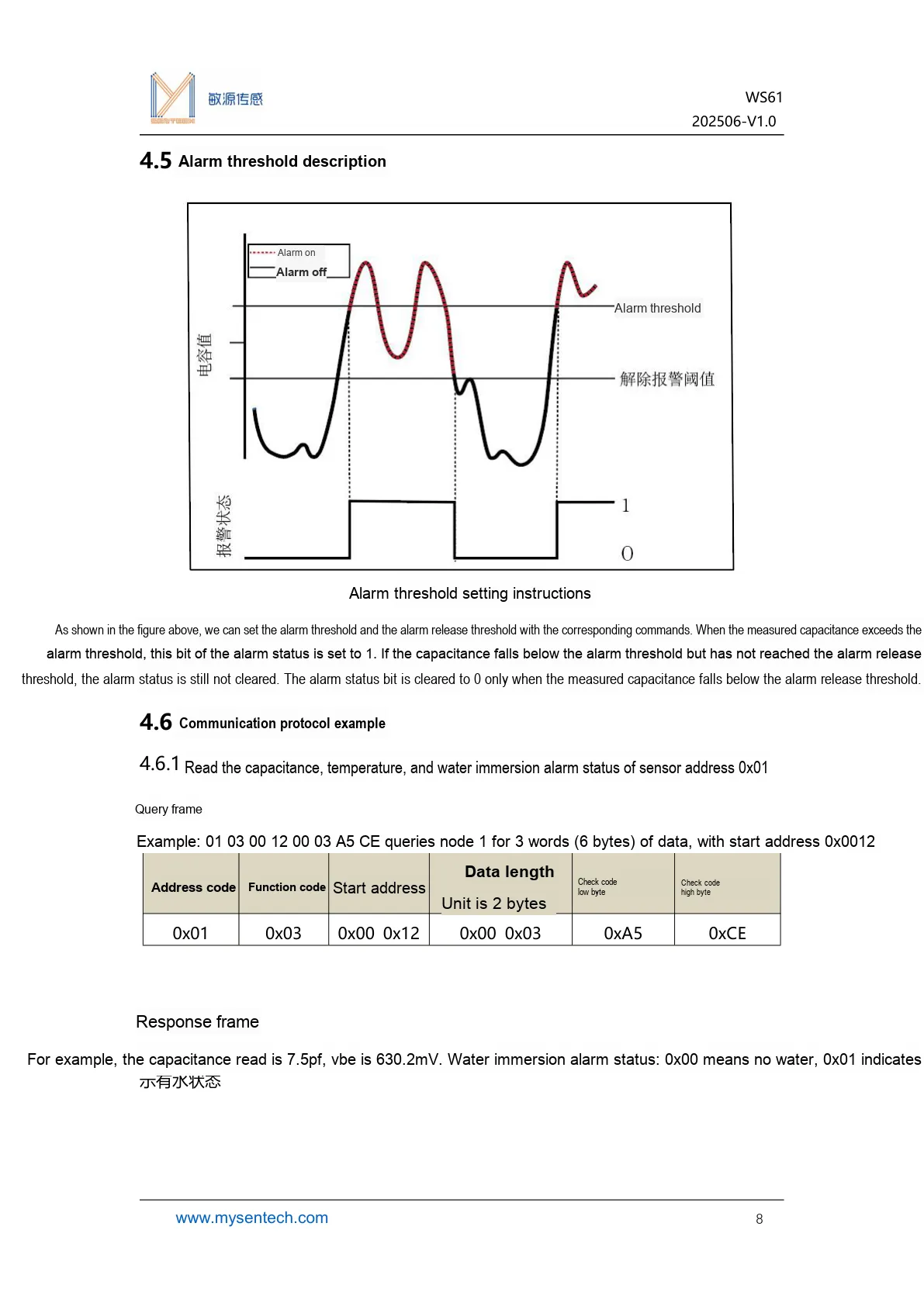
This diagram illustrates the alarm threshold description and communication examples, which can be used to configure and debug the water immersion alarm logic.
III. Circuit Engineering
3.1 Circuit Source Engineering
To obtain the source project of the circuit, please refer to the link below:
https://mysentech.com/productinfo/3228659.html
3.2 Module Usage Instructions
3.2.1 Module Test Environment Setup and Notes
Here, before testing, first fit the module with a waterproof casing (or seal the wiring terminals with waterproof adhesive), and a water leakage scenario can be simulated through a transparent plastic container. After powering on and confirming that the serial port data is stable, test with clean water through plastic plates of different thicknesses, and observe whether the water immersion level changes synchronously with the contact/separation of water.
Critical Notes: The module itself is not waterproof. It must be installed with a waterproof enclosure/sealed interface, and bare board shall be strictly prohibited from direct contact with water; the power supply voltage must not exceed 5.5V; during installation, it should be closely attached to the measured plane and kept away from metal objects to avoid affecting the accuracy of capacitance detection.
3.2.2 Usage of Modbus Poll
Modbus Poll is a universal Modbus master debugging tool compatible with all capacitive sensors in this series that support the Modbus-RTU protocol. It enables quick serial communication debugging, real-time data reading and log export between sensors and computers, serving as a universal host computer tool for verifying sensor functions and collecting test data. The software supports Modbus RTU/ASCII/TCP/IP protocols, is compatible with multiple register types and data formats, and its operation process is universal for the entire series of sensors.
Before use, you need to complete the software installation and activation first. You can download the installation package through official channels; the first launch supports a 30-day trial, and you can also enter a registration code for permanent activation. After the hardware connects the sensor to the computer, open the software and click "Connection" - "Connect", then configure the serial port parameters (Port Number, baud rate, data bit/parity bit/stop bit; this series of sensors defaults to the 9600 Baud, 8N1 format, subject to the specification sheet of the corresponding specific model) in the pop-up window, and confirm to establish a communication connection.
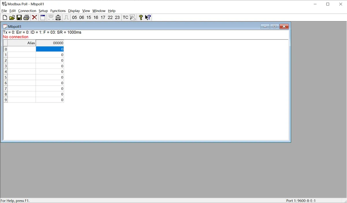
The following is a description of the general operation process:
- Serial Port Connection Configuration: After connecting the sensor to the computer via a USB-to-serial port module, launch the Modbus Poll software, click "Connection" - "Connect" on the menu bar, select the COM Port Number corresponding to the sensor in the pop-up window, and configure the serial port parameters matching the sensor (baud rate, data bits, parity check mode, stop bits; this series of sensors defaults to 9600 Baud, 8N1 format), then confirm to establish a communication connection.
- Import Sensor Configuration File: The software supports importing
. mbppre-configuration files corresponding to various sensor models. These files come with preset register addresses, data formats, and alias definitions, eliminating the need for manual register configuration. Simply open the. mbpfile for the corresponding sensor in the software to automatically load all parameters. Once the connection is established, real-time detection data of the sensor (such as dust/rain/frost thickness values, status flag bits, etc.) will be displayed directly. - Data Logging (Optional): If you need to save test data, you can configure logging rules via the "Setup" - "Excel Log" function. It supports logging data at fixed intervals or with every data update, and allows you to set a maximum number of log entries, facilitating subsequent analysis and verification of sensor data.
The above are the general basic operations of the host computer. For the. mbp preconfiguration files, specific register definitions and special configuration details of different sensor models, please refer to the content in "VII. Related Materials".
3.3 Application Experiment
Here, we use the GraftPort-RP2040 development board for testing, and the water immersion module WS61 uses the UART interface to communicate with the main controller.
Here, we first use the HY2.0-4P cable to connect the module via the XH2.54-4P to HY2.0-4P interface module to the GraftPort-RP2040 development board's UART0 interface:
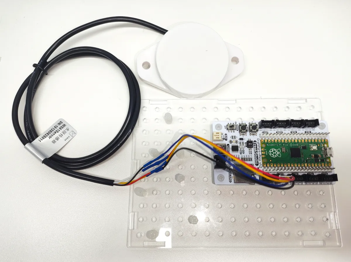
This diagram illustrates the UART wiring method between the WS61 module and GraftPort-RP2040 development board.
The module connections are shown in the following table:
Development Board Pins | Module Pins | Description |
Pin 16 |
|
|
Pin 17 |
|
|
Here, we need to search for the relevant driver packages on uPyPI: https://upypi.net/zh/
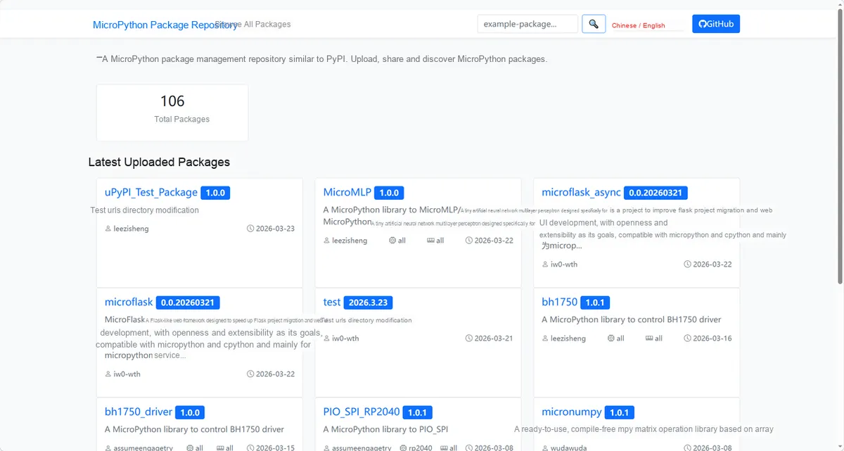
This diagram demonstrates the process of searching for the WS61 driver package in uPyPI.
Enter ws61_driver to search, and the following will be displayed:
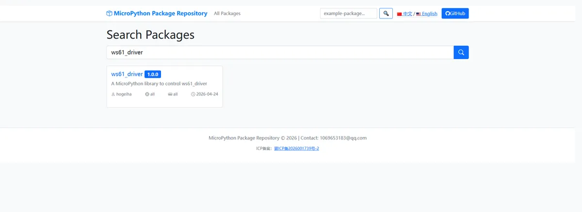
This diagram illustrates the ws61_driver search results, which are used to confirm the corresponding driver package.
Click to copy the local installation command:
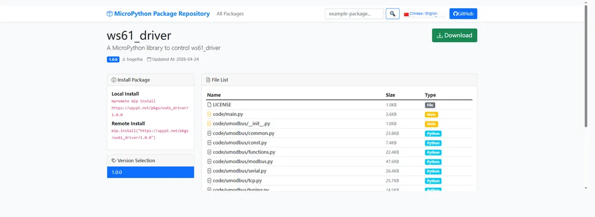
This diagram shows the interface for copying the WS61 driver installation command, to facilitate the completion of environment preparation.
Import the module driver library code via the mip tool. Below are the usage commands for the mpremote tool:
mpremote mip install https://upypi.net/pkgs/ws61_driver/1.0.0Import the WS61 water immersion module MicroPython driver code, then copy the following main.py code into our project:
# Python env   : MicroPython v1.23.0
# -*- coding: utf-8 -*-
# @Time    : 2026/4/3 2:30 PM
# @Author  : FreakStudio
# @File    : main.py
# @Description : WS61 water immersion sensor data acquisition main program

# ======================================== Import Modules =========================================

import time
from wd61 import WS61Water

# ======================================== Global Variables ============================================

# ======================================== Functions ============================================

# ======================================== Custom Classes ============================================

# ======================================== Initialization configuration ===========================================

# Wait for hardware to stabilize
time.sleep(3)
# Output initialization message (English only)
print("FreakStudio: WS61 Water Sensor Initialization")

# Create sensor object, configure slave address, UART number, TX and RX pins
sensor = WS61Water(slave_addr=1, uart_id=0, tx_pin=16, rx_pin=17)
# Write alarm capacitance threshold (unit: pF)
sensor.write_alarm_threshold(7.5)
# Write alarm release threshold (unit: pF)
sensor.write_release_threshold(7)

# ========================================  Main Program  ============================================

# Main loop: print all readable parameters
while True:
    # Read device ID
    dev_id = sensor.read_device_id()
    # Read 485 node address
    node_addr = sensor.read_485_node_address()
    # Read alarm capacitance threshold
    alarm_th = sensor.read_alarm_threshold()
    # Read alarm release threshold
    release_th = sensor.read_release_threshold()
    # Read real-time capacitance value
    cap = sensor.read_capacitance()
    # Read ambient temperature
    temp = sensor.read_temperature()
    # Read water immersion status (1: water alarm, 0: no water)
    status = sensor.read_water_status()

    # Print all parameters in formatted form (English-only output)
    print("=" * 60)
    print(f"Device ID: {dev_id if dev_id is not None else 'Read failed'}")
    print(f"485 Node Address: {node_addr if node_addr is not None else 'Read failed'}")
    print(f"Alarm threshold: {alarm_th} pF" if alarm_th is not None else "Alarm threshold: Read failed")
    print(f"Release threshold: {release_th} pF" if release_th is not None else "Release threshold: Read failed")
    print(f"Capacitance: {cap} pF" if cap is not None else "Capacitance: Read failed")
    print(f"Temperature: {temp} C" if temp is not None else "Temperature: Read failed")
    print(f"Water status: {'Water alarm' if status == 1 else 'No water'}" if status is not None else "Water status: Read failed")
    print("=" * 60)

    # Delay 1 second
    time.sleep(1)
Burn the code, open the terminal, and the output is as follows:
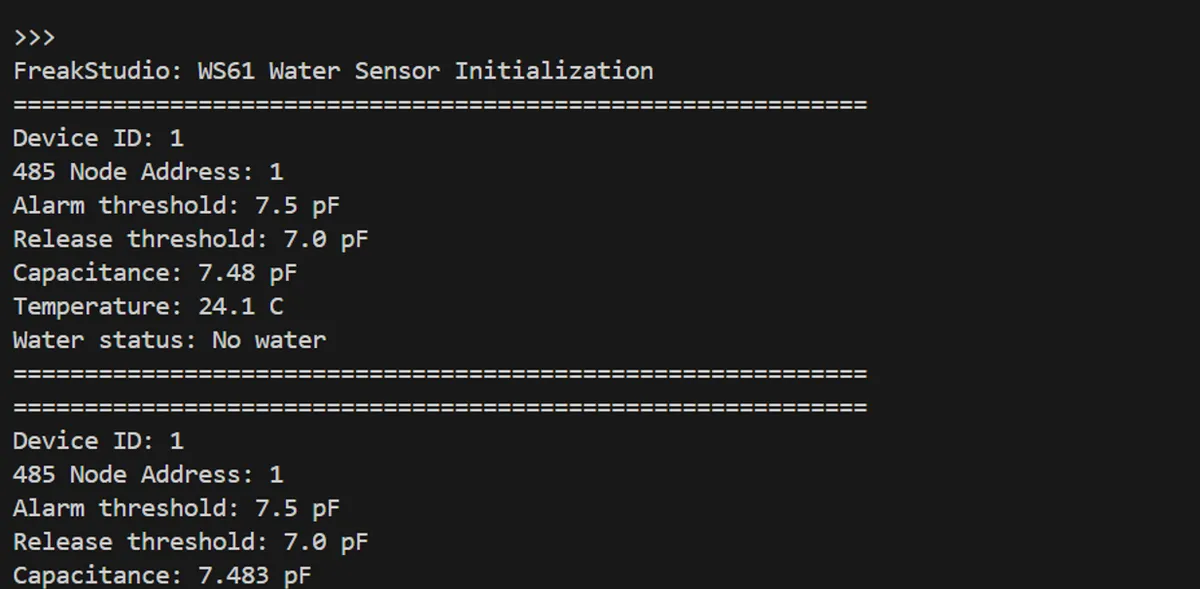
This figure shows the first half of the output of the WS61 sample program, including information such as device addresses and thresholds.
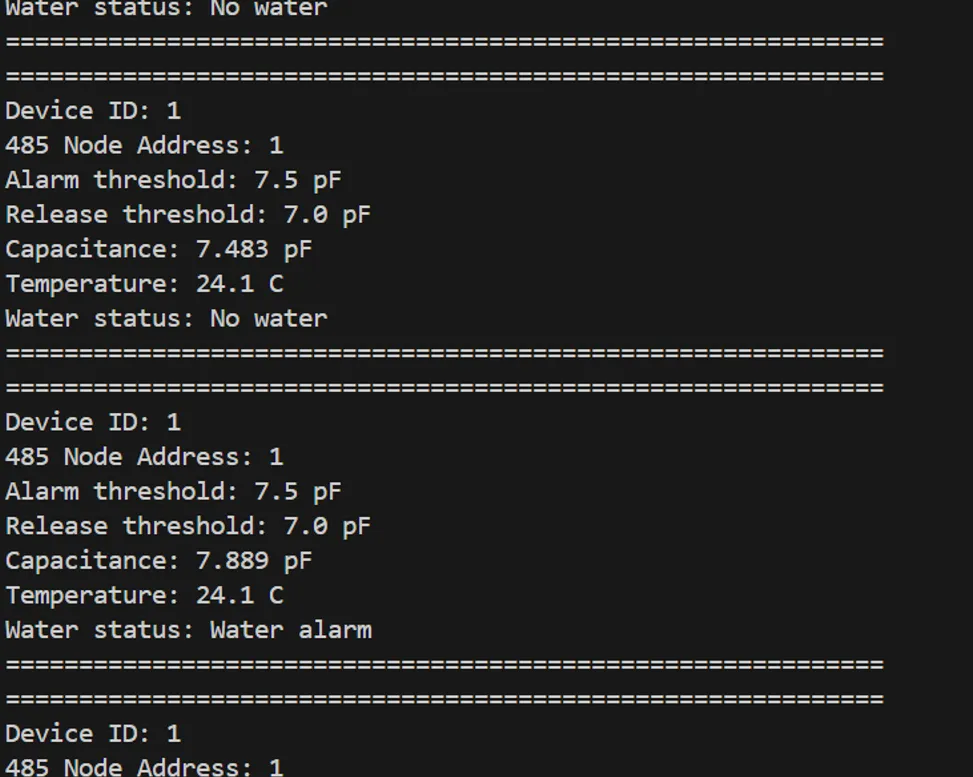
This figure shows the latter part of the output of the WS61 sample program, including information on capacitance, temperature and water immersion status.
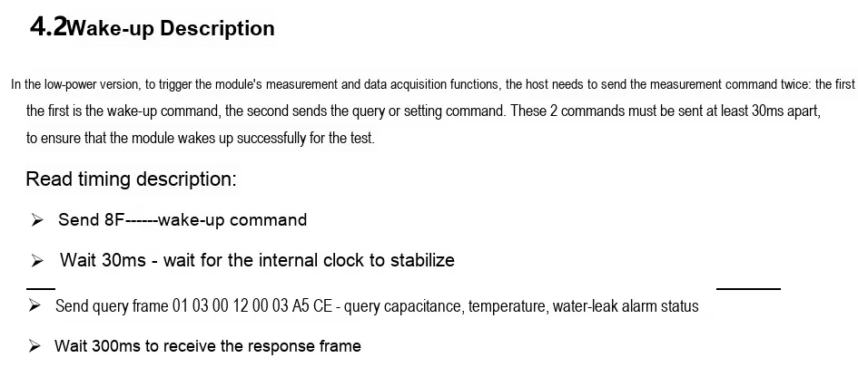
Here, it should be noted that our driver library code has already encapsulated the two read operations, so developers do not need to perform the reading twice.
4. Drivers
ws61_driver.zip 44 KB
5. BOM & Recommended Alternative Parts
None.
VI. Revision History
Document Version | Date of Revision | Modifier | Modify Content |
v1.0 | 2026-08-21 | Mi Ming Xuan | Initialize the document |
VII. Relevant Materials
WS61 Water Immersion Sensor Product Introduction-Minyuan 202506-2.pdf 1.2 MB
WS11.mbp 3 KB