Contents
- 1. Module Introduction
- 2. Introduction to Main Chips
- 2.1 Chip Overview
- 2.2 Pin Definitions
- 2.3 Functional Block Diagram
- 2.4 Performance Parameters
- 2.5 Reference Circuit
- 2.6 Chip Configuration
- 2.7 Communication Interfaces and Related Protocols
- 2.8 PCB Wiring Precautions
- III. Circuit Engineering
- 3.1 Circuit Source Engineering
- 3.2 Module Usage Instructions
- 3.3 Application Experiment
- 4. Driver
- 5. BOM & Recommended Alternatives
- 6. Change History
- VII. Related Materials
- 7.1 Chip Data Sheet
- 7.2 Special Icons for PCB Silk Screen
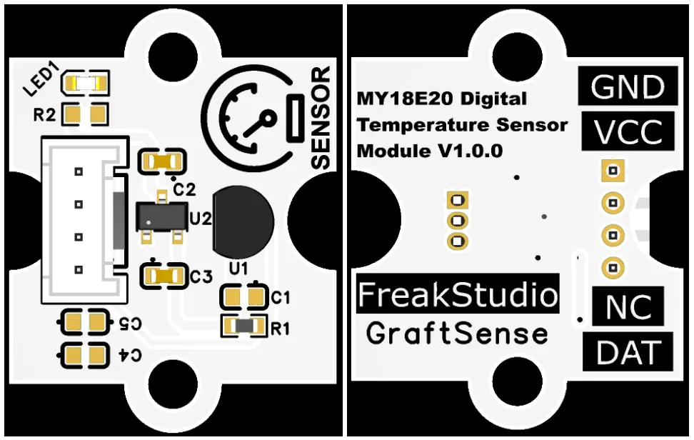
1. Module Introduction
Digital Temperature Sensor Module Based on MY18E20, using Minyuan Sensing MY18E20 digital temperature sensor solution, can directly output ambient temperature data and is compatible with DS18B20; the module is equipped with LDO voltage regulator circuit, power supply filtering and indicator light circuit, powered by 3.3V and communicates with the main controller through the single-bus protocol, supports multi-chip networking, achieves ±0.5°C accuracy measurement within the range of -10°C to +85°C, has low power consumption, and is suitable for multi-point temperature measurement, temperature monitoring, and low-power device scenarios.
2. Introduction to Main Chips
MY18E20 is a single-wire digital temperature sensor chip launched by Minyuan Sensing, TO-92 package, powered by 1.8~5.5V, with a temperature measurement range of -55°C~+125°C, accuracy of ±0.5°C from -10°C~+85°C, default 12-bit ADC (configurable to 14-bit), low power consumption, and built-in unique 64-bit ID and 80-bit EEPROM.
2.1 Chip Overview
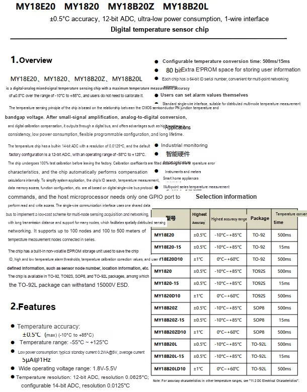
MY18E20 is a single-wire digital temperature sensor chip from Minyuan Sensing, with a temperature measurement range of -55°C to +125°C, an accuracy of ±0.5°C from -10°C to +85°C, and a default 12-bit ADC (configurable to 14-bit), low power consumption, support for multi-point networking, and compatibility with TO-92 package, widely used in scenarios such as industrial monitoring and smart home.
2.2 Pin Definitions
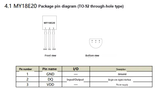
MY18E20 ( TO-92 package) is a three-pin device: Pin 1 GND is grounded, Pin 2 DQ is a single-bus digital interface (bidirectional I / O ), and Pin 3 VDD is connected to the power supply.
2.3 Functional Block Diagram
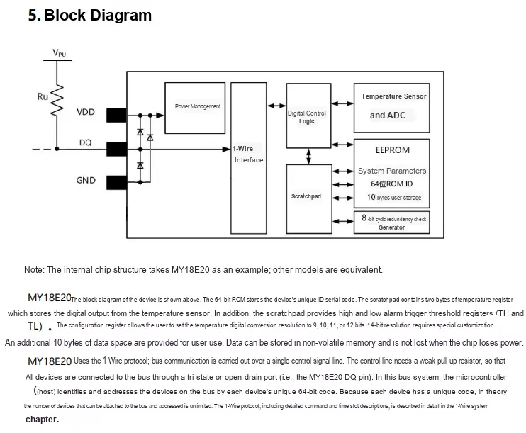
MY18E20 incorporates built-in power management, a single-wire interface, digital control logic, temperature sensing, and analog-to-digital conversion modules, paired with EEPROM ID containing a unique 64-bit ROM and scratchpad, communicating via the single-wire DQ pin with an external pull-up, supporting multi-node networking, user data storage, and temperature alarm configuration.
2.4 Performance Parameters
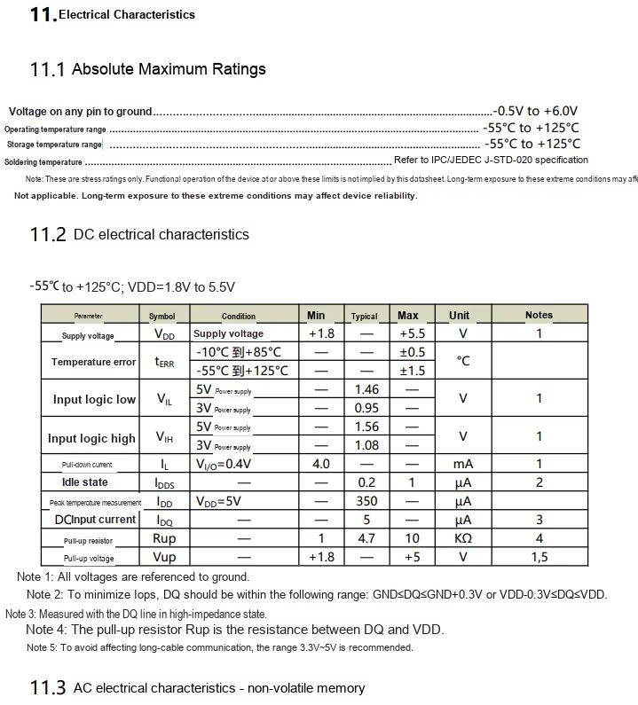

MY18E20 electrical parameters, with a supply voltage of 1.8~5.5V, a temperature measurement range of -55°C~+125°C, a typical accuracy of ±0.5°C, and also specifies the pin limit voltage and temperature range; the maximum write cycle of the non-volatile memory is 40ms.
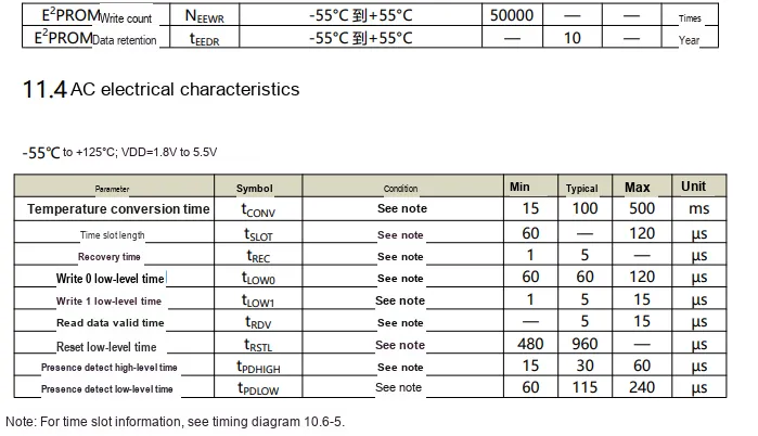
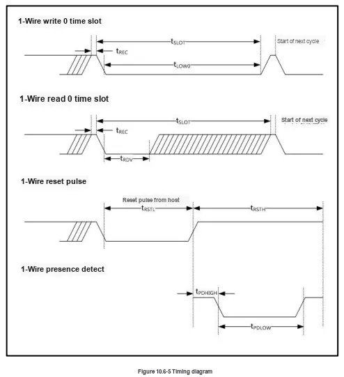
MY18E20's E²PROM has a number of erasable and writable cycles ≥50,000 times and data retention ≥10 years; in terms of AC characteristics, the temperature conversion time is 15~500ms (configurable), and at the same time, key timing parameters such as reset, read, and write required for single-bus communication are specified.
2.5 Reference Circuit
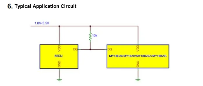

MY18E20 Digital Temperature Sensor's typical application circuit, MCU shares a 1.8V~5.5V power supply and ground with the sensor, and communicates via the single-wire bus DQ pin; DQ line is pulled high by a 10kΩ pull-up resistor to implement the standard single-wire bus protocol, MCU sends commands and reads temperature data through this pin.
2.6 Chip Configuration
None.
2.7 Communication Interfaces and Related Protocols
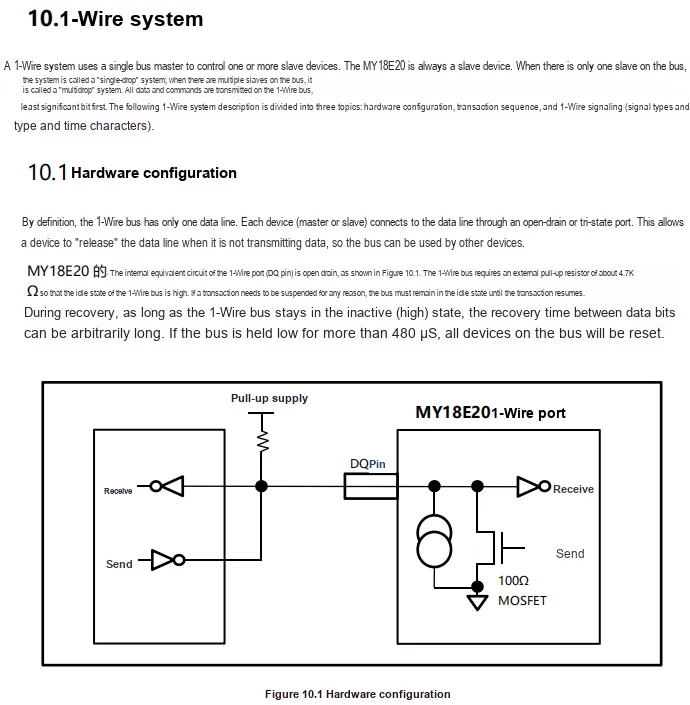
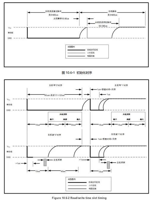
MY18E20 single-bus hardware configuration, DQ pin has an internal open-drain structure and requires an external pull-up resistor of approximately 4.7kΩ to keep the bus at a high level when idle; the host connects to the bus through an open-drain/tri-state port to enable multi-point device shared communication. If the bus is pulled low for more than 480μs, all devices will be reset.
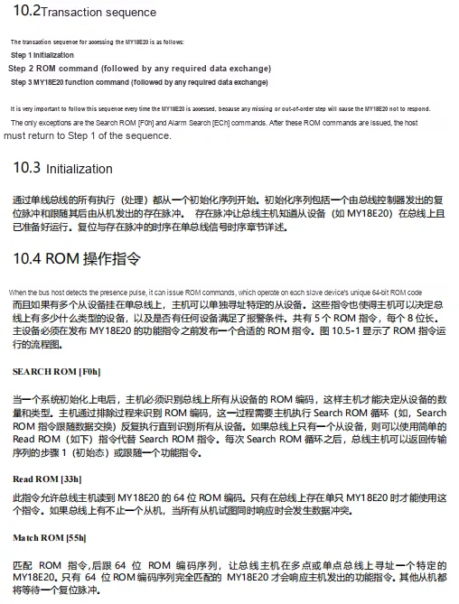
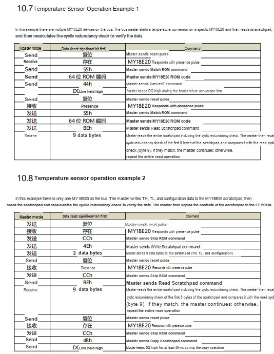
MY18E20's single-bus access process must be executed according to "Initialization → ROM Command → Function Command". Initialization includes the host reset pulse and the slave presence pulse; ROM commands (such as Read ROM, Match ROM) implement addressing based on the device's unique 64-bit ID, supporting single-point/multi-point networking and alarm device query.
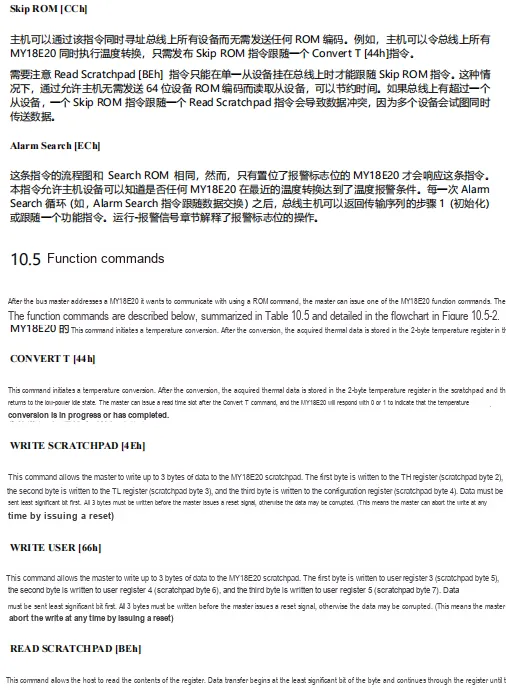
MY18E20 single bus instructions, including:
ROMInstruction :Skip ROM (CCh)can address all devices on the bus simultaneously,Alarm Search (ECh)only responds to devices that meet the alarm condition.- Function Instruction:
Convert T(44h)initiates temperature conversion,Write Scratchpad(4Eh)writes to TH/TL and configuration registers,Read Scratchpad(BEh)reads scratchpad data, implementing core functions such as temperature reading and alarm setting.
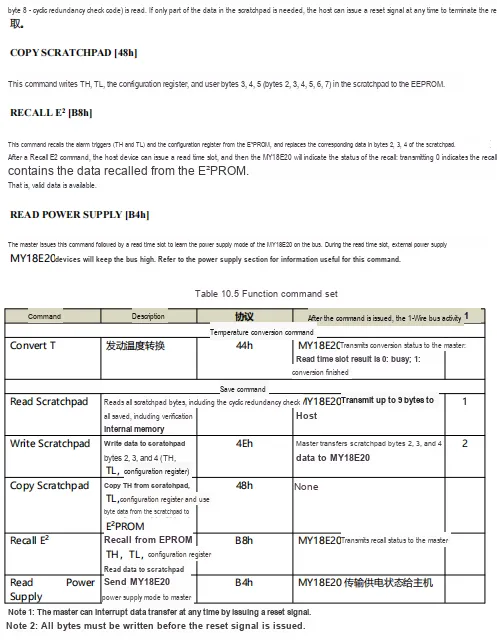
MY18E20's single bus function instruction set includes instructions such as temperature conversion, register read/write, E²PROM backup and restore, power supply mode query, etc. Each instruction defines specific functions, operation codes, and bus interaction methods, through which the host can implement temperature reading, configuration saving, and status detection.
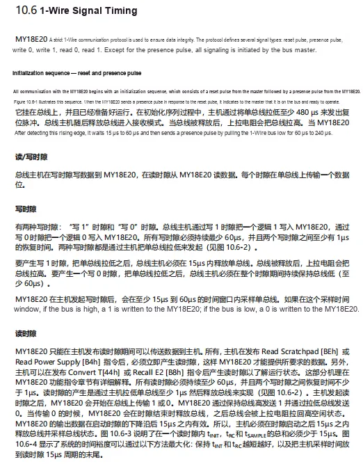
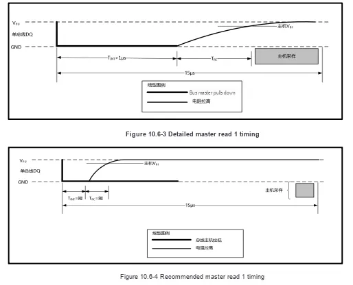
MY18E20's single bus timing includes three types of signals: initialization, write time slot, and read time slot. Initialization requires the host to pull the bus low for ≥480μs for reset, then release the bus and wait for 15-60μs, after which the device pulls the bus low for 60-240μs to send a presence pulse; the write time slot (write 0 / write 1) is initiated by the host pulling the bus low, lasting ≥60μs with an interval of ≥1μs, and the device samples within 15-60μs after the pull low;The read time slot is released by the host after pulling the bus low for ≥1μs. The device outputs data within 15μs after the pull-down, and the host needs to sample within this window. All time slots must strictly adhere to the timing requirements to ensure reliable communication.
2.8 PCB Wiring Precautions
None.
III. Circuit Engineering
3.1 Circuit Source Engineering
ProPrj_Digital Temperature Sensor Module Based on MY18E20_v1.0.0_2026-05-12.epro2 2.9 MB
Digital Temperature Sensor Module Based on MY18E20-V1.0.0.rar 3.3 MB
3.2 Module Usage Instructions
The schematic diagram of this module is as follows:
SCH_Schematic1_Digital Temperature Sensor Module Based on MY18E20_v1.0.0_2026-05-12.pdf 2.3 MB
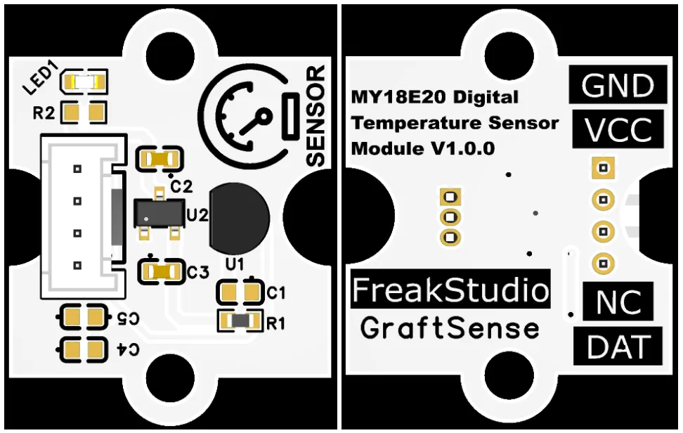
This module provides a single bus ( 1-Wire ) communication interface DAT : compatible with DS18B20 protocol, supports standard single bus multi-point networking, can stably transmit MY18E20 collected digital temperature data, achieves ±0.5°C accuracy measurement within the range of -10°C to +85°C, suitable for multi-point temperature measurement, temperature monitoring, and low-power device scenarios, providing the system with reliable single bus temperature sensing data interaction capabilities.
3.3 Application Experiment
Here, we use the GraftPort-RP2040 development board for testing, and on the digital temperature sensor module based on MY18E20 we use the DIO interface to communicate with the main controller.
Here, we first use the HY2.0-4P connection cable to connect the module to the GraftPort-RP2040 development board's DIO0 interface:
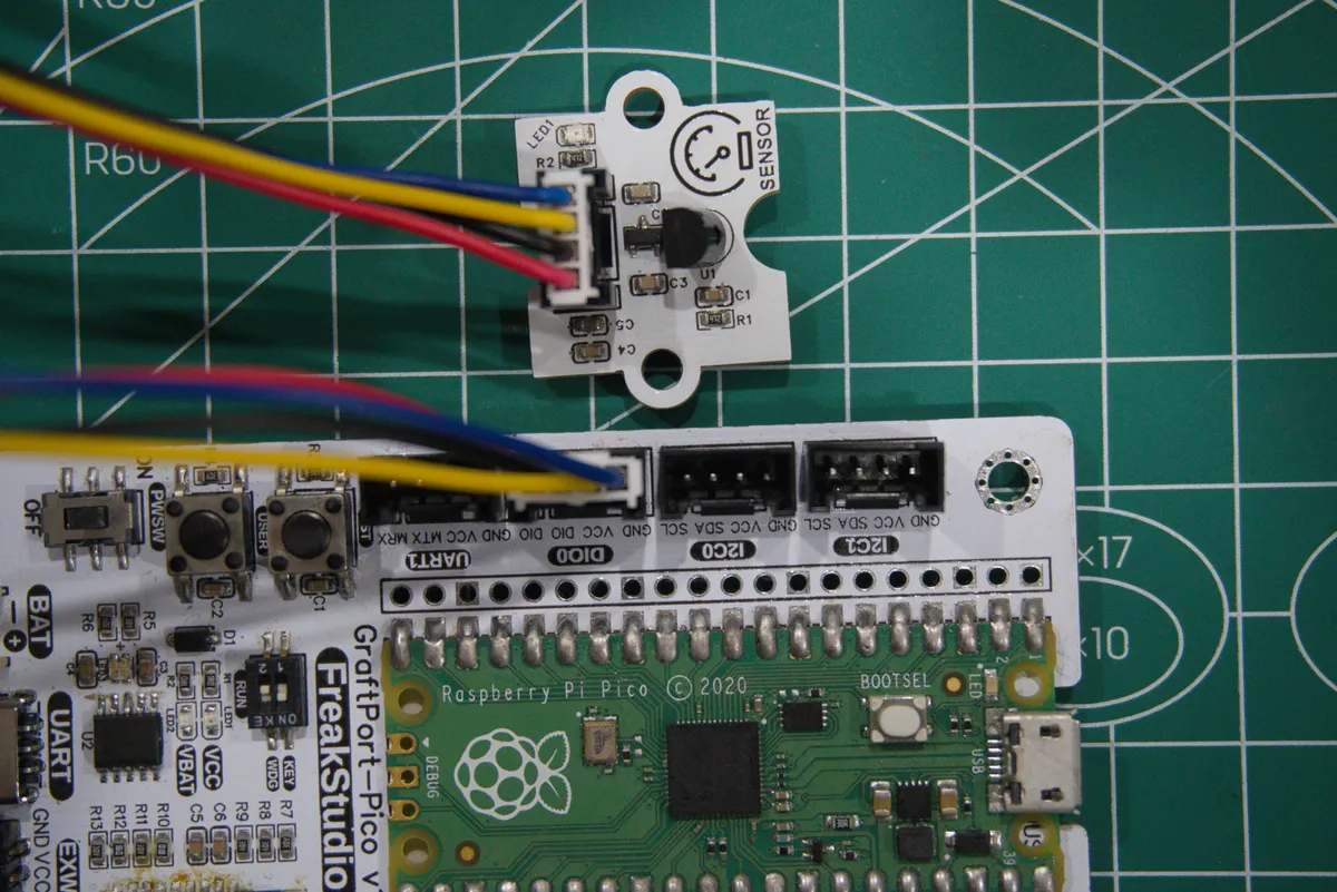
Module connections are shown in the following table:
Development Board Pins | Module Pin | Instructions |
Pin 6 |
| Single-bus communication pin |
Pin 7 |
| - |
Here, we need to search for relevant driver packages on uPyPI:https://upypi.net/zh/
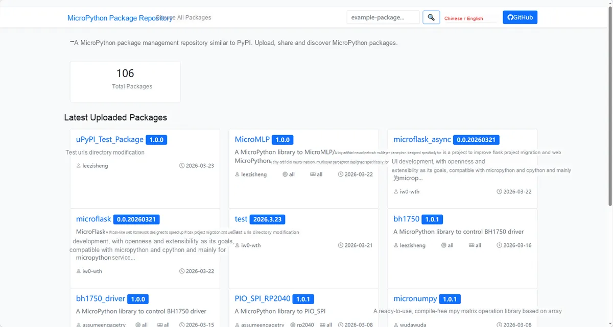
Enter my18e20_driver to search, and the display is as follows:
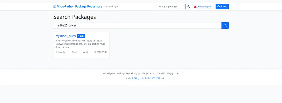
Click to copy the local installation command:
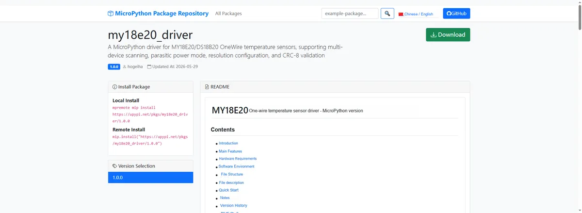
Import module driver library code via mip tool, the following are the usage instructions for mpremote tool:
mpremote mip install https://upypi.net/pkgs/my18e20_driver/1.0.0After importing the MicroPython driver code for the digital temperature sensor module based on MY18E20 , copy the following main.py code into our project:
# Python env   : MicroPython v1.23.0
# -*- coding: utf-8 -*-
# @Time    : 2024/7/22 15:01
# @Author  : Li Qingshui
# @File    : main.py
# @Description : Code for testing the MY18E20 temperature sensor driver class
# @License : MIT

# ======================================== Import Modules =========================================

# Import hardware-related modules
from machine import Pin

# Import time-related modules
import time

# Import modules for single-bus communication
from onewire import OneWire

# Import the temperature sensor class
from my18e20 import MY18E20

# ======================================== Global Variables ============================================

# Print interval (ms)
PRINT_INTERVAL_MS = 500

# ======================================== Functions ============================================

# ======================================== Custom Classes ============================================

# ======================================== Initialization ==========================================

# Wait for the device to power up and stabilize
time.sleep(3)
print("FreakStudio: Using MY18E20 OneWire temperature sensor ...")

# Initialize the 1-Wire pin and sensor object
ow_pin = OneWire(Pin(6))
sensor = MY18E20(ow_pin)

# Scan the bus for devices and get the list of ROM addresses
roms_list = sensor.scan()
# Print the ROM addresses of all devices
for rom in roms_list:
    print("Detected sensor ROM ID: %s" % str(rom))

# Start the first temperature conversion
sensor.convert_temp()

# ========================================  Main Program  ===========================================

try:
    while True:
        # Wait for the conversion to finish (up to 750 ms at 12-bit resolution)
        time.sleep_ms(PRINT_INTERVAL_MS)
        # Read and print the temperature of each sensor
        for rom in roms_list:
            temp = sensor.read_temp(rom)
            print("Sensor %s temperature: %s C" % (str(rom), str(temp)))
        # Start the next temperature conversion
        sensor.convert_temp()

except KeyboardInterrupt:
    print("Program interrupted by user")
except OSError as e:
    print("Hardware communication error: %s" % str(e))
except Exception as e:
    print("Unknown error: %s" % str(e))
finally:
    print("Cleaning up resources...")
    del sensor
    del ow_pin
    print("Program exited")
Burn the code, open the terminal, and the output is as follows:
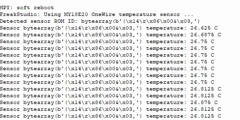
The MY18E20 single-bus temperature sensor has been initialized normally, successfully identified the ROM ID, and can stably output temperature data. The readings fluctuate slightly between 26.625°C and 26.875°C, with a stable operating state.
4. Driver
my18e20_driver-1.0.0.zip 14 KB
5. BOM & Recommended Alternatives
BOM_Digital Temperature Sensor Module Based on MY18E20_v1.0.0.xlsx 11 KB
ModAcc_Digital Temperature Sensor Module Based on MY18E20_v1.0.0.xlsx 10 KB
6. Change History
Document Version | Modification Date | Modifier | Modified Content |
v1.0 | 2026-05-12 | Linggaoxing | Initialize Document |
VII. Related Materials
7.1 Chip Data Sheet
MY18E20.pdf 1.8 MB
7.2 Special Icons for PCB Silk Screen